
Figures & data
Figure 1. (A) The 6 ABangle VH-VL parameters that describe the variable degrees of freedom of VH-VL orientation consist of the torsion angle HL, from H1 to L1 measured about C, the bend angle HC1, between H1 and C, the bend angle HC2, between H2 and C, the bend angle LC1, between L1 and C, the bend angle LC2, between L2 and C, and the length of C, dc (not shown). (B) Residues belonging to the VH-VL orientation fingerprint, shown in stick representation, and the resulting fingerprint string. CDR color coding follows IMGT/Collier-de-PerlesCitation23 conventions: CDR-H1 is colored red, CDR-H2 orange, CDR-H3 purple, CDR-L1 blue, CDR-L2 light green, and CDR-L3 dark green. The example shows the crystal structure with PDB ID 3PP4.Citation24
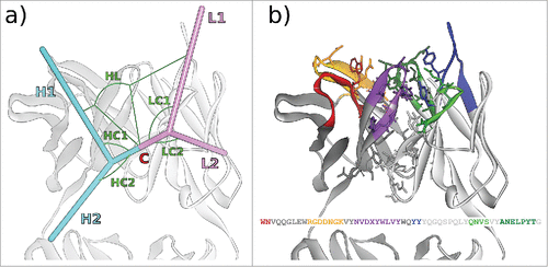
Figure 2. VH (top) and VL (bottom) sequences of the 3 rodent antibodies CD81K04, CD81K13, and Rb86. Framework and CDR classification follows WolfGuy nomenclature. Sequence positions that are part of the VH-VL orientation fingerprint are highlighted with a gray background. VH-VL orientation fingerprint positions that are unpopulated in a given antibody are denoted with the letter X. CDR color coding as described in Fig. 1.
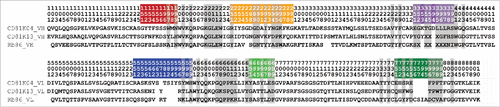
Figure 3. Fv regions of the antibodies a) CD81K04 (PDB ID 5DFV), b) CD81K13 (PDB ID 5DFW), and c) Rb86 (5DMG) in complex with their respective antigen (colored yellow), shown in frontal (top) and top view (bottom). Capital letters in panels a) and b) indicate the helix names of CD81 LEL. In panel c), the location of phosphoserine in the peptide derived from tau/pS422 is highlighted with an asterisk. CDR color coding as described in Fig. 1.
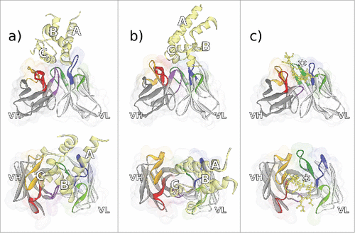
Figure 4. Non-bonded interactions at the antibody-CD81 LEL interface of antibodies a) CD81K04 and b) CD81K13. Capital letters indicate the helix names of CD81 LEL. Hydrogen bonds indicated as green dotted lines, hydrophobic interactions indicated as magenta dotted lines, and electrostatic interactions indicated as orange dotted lines. CDR color coding as described in Fig. 1.
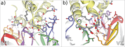
Figure 5. Non-bonded interactions at the interface of antibody Rb86 and the peptide derived from tau/pS422 from 2 different perspectives a) facing the VL interface, and b) facing the VH interface. From the co-crystallized 15-mer 416–430 of tau, only the segment 419–430 (MVDpSPQLATLAD) was assignable. Hydrogen bonds indicated as green dotted lines, hydrophobic interactions indicated as magenta dotted lines, and electrostatic interactions indicated as orange dotted lines. CDR color coding as described in Fig. 1.
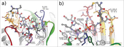
Figure 6. ABangle VH-VL orientation vectors calculated from the crystal structures of CD81K04 (cyan), CD81K13 (copper) and Rb86 (pink). The ribbon representation shows the crystal structure of CD81K04. Residues included in the VH-VL orientation fingerprint are shown in stick representation. Multiple vectors of the same color refer to multiple copies of the same Fv in the asymmetric unit of the respective crystal structure. CDR color coding as described in Fig. 1.
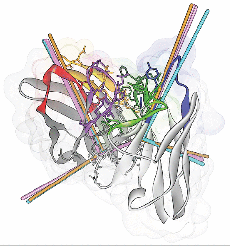
Figure 7. The antibody crystal structures of CD81K04 (cyan), CD81K13 (copper) and Rb86 (pink) in ABangle VH-VL orientation space. For each of the 6 ABangle parameters, the background distribution of the redundant set of known antibody crystal structures is shown as a histogram. The predicted ABangle values are indicated by circles (leave-one-out predictor) and squares (all-knowing predictor).
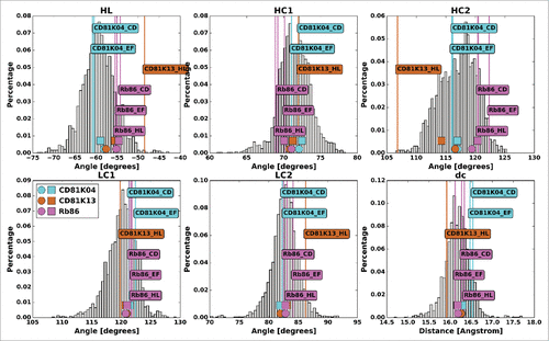
Figure 8. VH (top) and VL (bottom) sequences of CD81K04 and humanized sequence variants thereof. Framework and CDR classification follows WolfGuy nomenclature. CDR color coding follows IMGT/Collier-de-PerlesCitation23 conventions: CDR-H1 is colored red, CDR-H2 orange, CDR-H3 purple, CDR-L1 blue, CDR-L2 light green, and CDR-L3 dark green. Sequence positions that are part of the VH-VL orientation fingerprint are highlighted with a gray background. Sequence positions that are part of the VH-VL orientation fingerprint but deviate from the parental sequence are highlighted with a green background.
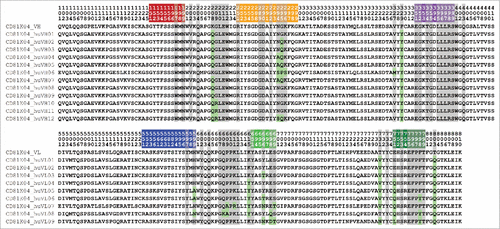
Table 1. Matrix of binding cell ELISA results for antibody CD81K04 (denoted as Ref.) and its humanization variants (unitless absorbance).
Table 2. distABangle matrix for the humanization variants of antibody CD81K04 (denoted as Ref.), calculated using the leave-one-out predictor.
Table 3. distABangle matrix for the humanization variants of antibody CD81K04 (denoted as Ref.), calculated using the all-knowing predictor.
Table 4. RV coefficients and associated p-values for the different binding signal matrix-distABangle matrix pairs.
Table 5. Pearson correlation coefficients and associated p-values for the different binding signal matrix-distABangle matrix pairs. The correlation is calculated on vectorised versions of the respective matrices.
Figure 9. VH (top row) and VL (bottom row) humanization variants of CD81K04, CD81K13 and Rb86, sorted by average distABangle value over all possible pairings (all-knowing ABangle predictor). The letter R denotes the non-human reference VH or VL. The dashed line indicates 80% of the maximum distABangle value, the threshold used for automatic rejection of a given variant.
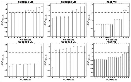
Figure 10. Overlay of the CD81K04 binding cell ELISA matrix (green indicates high binding signals, red low binding signals) with the selection matrix for each of the 3 rejection methods (darkened cells indicate rejected VH-VL pairs). The letter R denotes the murine reference VH or VL. Panel a) shows selections based on the leave-one-out predictor, panel b) shows selections based on the all-knowing predictor.
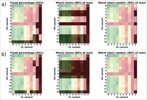
Figure 11. CD81K04: Normalized histograms of the binding signal range of kept (dark gray) and rejected subset (light gray) for each of the 3 distABangle-based rejection methods. Binding signal values are taken from the CD81K04 binding cell ELISA matrix. Results in panel a) are based on selections made using the distABangle matrix from the leave-one-out predictor, while results in panel b) are based on selections made using the distABangle matrix from the all-knowing predictor.
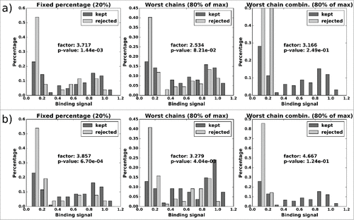
Figure 12. CD81K13: Normalized histograms of the binding signal range of kept (dark gray) and rejected subset (light gray) for each of the 3 distABangle-based rejection methods. Binding signal values are taken from the CD81K13 binding cell ELISA matrix. Panels a) and b) as described in Fig. 11.
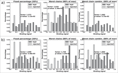
Figure 13. Rb86: Normalized histograms of the binding signal range of kept (dark gray) and rejected subset (light gray) for each of the 3 distABangle-based rejection methods. Binding signal values are taken from the RB6 BL matrix. Panels a) and b) as described in .
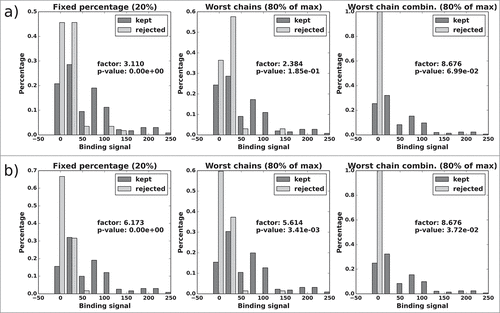
Table 6. Binding signal median change factor, p-value and number of total and rejected VH-VL pairs (“tot./rej.”) for each of the 3 humanization candidate selection methods.