
Figures & data
Figure 1. Stapling of scFv. (a) scFv stapling to improve low stability and minimize breathing-mediated aggregation. (b) Cartoon schematic of the stapling scheme using HL configuration as example. A similar scheme is valid for the LH construct. Pink dashed lines indicate flexible linkers connecting the C-terminus of leading variable region and the N-terminus of the trailing variable region to the stapling ‘CPPC’ motif. The segment labeled CPPC in the middle of the linker indicates one possible design of a staple which occurs naturally in the IgG1 hinge. Anchor points (labeled C(APL) and C(APH)) that are mutated to Cys residues in VH and VL are shown in stick. Short lines (yellow) between the staple and anchor point Cys residues indicate disulfide bond formation. Distances dstaple and dAP (yellow, dashed line) are labeled (c) Graphical illustration of anchor point selection geometry consideration (HL configuration) mapped onto the structure of an Fv from a human germline antibody (PDB ID 5I19, GLk1). Cter: C terminus of leading domain; Nter: N terminus of trailing domain; APH: anchor position on leading domain; APL: anchor position on trailing domain; dAP: distance between APH and APH; d1-d4: various distances as defined in the figure. Similar illustrations can be drawn for the LH orientation (not shown). Anchor points for HL orientation are Chothia position 43 for VH (H43C) and position 100 for VL (L100C); for LH: Chothia position 42 in VL (L42C) and 105 in VH (H105C). (d, e) Cβ(Cys1)-Cβ(Cys2) distance between Cys residues in hinge CPPC motifs in structures of human IgG4 (PDB 5DK3; (d) and mouse IgG2a (PDB 1IGT; (e). These distances range from about 7 Å to 9 Å.
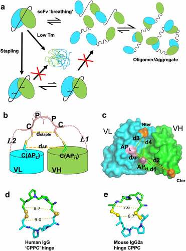
Figure 2. Stapling design improves the thermal stability of Cris7a/b domains. (a) SDS-PAGE of scFv and spFv proteins of Cris7a/Cris7b in LH orientation. (b) Thermal stability of Cris7a scFv/spFv and Cris7b scFv/spFv domains by DSC. Parameters related to protein design and enthalpy features from analysis are listed in Table S1.
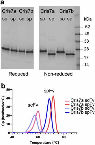
Figure 3. Structures and comparison of various scFv/spFv domains. In all structures, VL is colored blue and VH is colored green. The linker segments are colored pink. (a) GLk1 spFv LH. (b) GLk1 spFv HL. (c) GLk2 spFv HL. (d) 2mfo-dFc electron density contoured at 1.5 σ about the CPPC staple motif and anchor points for Glk2 spFv HL. Circles in orange indicate the stapling disulfide density. (e) CAT2200b spFv HL. (f) unbound CAT2200b spFv HL compared with CAT2200a scFv LH bound to IL-17 (silver). (g) front and back views of unbound CAT2200b spFv HL compared with CAT2200a spFv LH bound to IL-17 (silver).
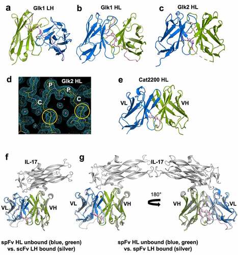
Figure 4. The staple and linker conformations in 5 spFv structures (bright green, GLk1 spFv LH; light pink, GLk1 spFv HL; purple, GLk2 spFv HL; light green, CAT2200 spFv LH bound to IL-17; orange, CAT2200 spFv HL unbound). The CPPC motif has been re-labeled as Cys1, Pro1, Pro2, Cys2 for clarity. The structures are superimposed on the mainchain of the CPPC motif. The dashed lines indicate Cα-Cα and Cβ-Cβ distances between the Cys1 and Cys2 residues. The range of Cβ-Cβ distances observed in all copies of the linker staple Cys residues are indicated. N-termini are indicated with ‘Nter’, C-termini are indicated with ‘Cter’.
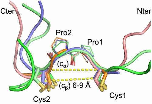
Figure 5. Bispecifics with spFv show improved yields, product quality and expected disulfide formation in the stapled linker. (a) Schematic of BCMA (Fab) x CD3 (scFv/spFv) bispecific molecular architecture. HK in Fc regions indicate the knob-in-hole (K, knob; H, hole) mutations for Fc heterodimerization. RF (H435R and Y436F) mutations in the Fab containing heavy chain are introduced for purification to prevent binding to Protein A of RF containing chain monomers or homodimers. (b) SEC profiles post-CH1 of scFv/spFv Cris7b containing molecules with mAb1 indicate presence of oligomer species (labeled O) in scFv proteins that is absent in spFv proteins (monomer, M). (c) MS2-HCD spectrum of the peptide derived from non-reduced proalanase digestion representing the expected stapled disulfide linkage between Cys119-Cys237. The b- and – y type backbone fragments from each peptide half are annotated in the sequence map that is composed of Pep1 and Pep2 connected via the disulfide bridge.
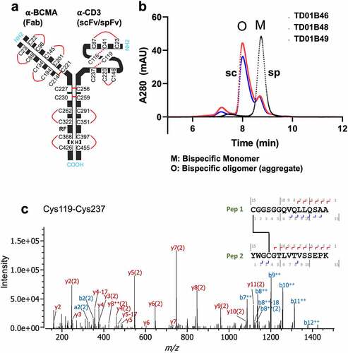
Figure 6. Cris7b spFv bispecific proteins with mAb1 are stable and retain binding affinity to CD3. (a) NanoDSF traces of Cris7b scFv/spFv bispecifics with mAb1 (TD01B49, TD01B46) show~10°C transition to higher Tm on incorporation of stapling mutations. (b, c) Cris7b spFv bispecific proteins are resistant to heat-induced aggregation. SEC traces (b) and quantification of aggregate levels (c) show that Cris7b spFv bispecifics have a dramatic reduction in heat-induced aggregation over 6 week time frame at either 4°C or 40°C. (d) BLI binding traces show comparable binding features (association and dissociation) for binding to recombinant CD3. Green: Cris7b spFv, TD01B46; blue: Cris7b scFv Bird, TD01B49; Orange dashed lines: Cris7b G4S, TD01B48.
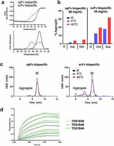
Figure 7. spFv bispecific molecules function similarly to their non-stapled counterparts. (a) spFv bispecific (TD01B46) has potent killing activity of BCMA+ cancer cells. (b, c) scFv (TD01B49)/spFv bispecifics (TD01B46) activate CD4+/CD25+ (b) and CD8+/CD25+ (c) T cells with similar potency. The negative control has no killing or T cell activating activity.
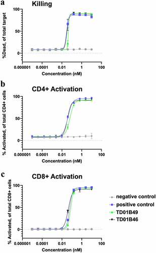
Table 1. Comparison of biophysical properties of scFv/spFv bi- and tri-specifics.
Supplemental Material
Download MS Word (3.9 MB)Data availability statement
Atomic coordinates and structure factors of spFv and scFv/spFc:antigen complexes have been deposited in the Protein Data Bank, www.rcsb.org, under the ID codes 8DY0, 8DY1, 8DY2, 8DY3, 8DY4 and 8DY5. All other data are included in the main text and SI.