Figures & data
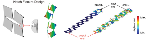
Figure 1. Kirigami cut design using a compliant beam as a notch flexure. (a) Comparison of conventional cut and compliant beam cut. With the new design, the undeformed and planarly deformed configurations are illustrated. (b) Two types of buckled morphology at different level of applied deformation for perforated sheets with and 0.2.
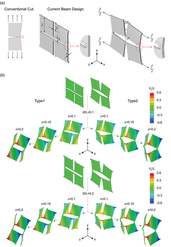
Figure 2. Experimental and FEM study of the kirigami sheets. (a) Experiment setup and view of the perforated sheet. (b) Stress–strain curve of the plastic sheet under uniaxial tension. (c) Snapshots of the sample with at
, 0.15 and 0.2. (d) Quantitative comparison between experimental and numerical stress–strain curves. Results for different patterns with
,
.
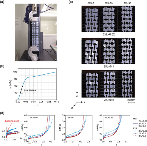
Figure 3. Response of kirigami sheets subjected to uniaxial tension. (a) Comparison between numerical and theoretical effective Young’s modulus (with ) and critical strain. (b) Effective Young’s modulus of perforated sheet (with
,
). (c) Critical strain of perforated sheet (with
,
).
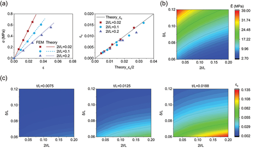
Figure 4. Effect of material behavior on the response of kirigami sheets subjected to uniaxial tension. (a) Comparisons between numerical stress–strain curves obtained considering an elastoplastic (solid line) and a purely elastic (dashed line) material model. (b) Effect of the geometric parameters on the stress–strain curves of the elastoplastic kirigami sheets.
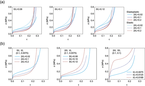
Figure 5. Increase the width of cuts to improve the strength and stretchability of kirigami structures. (a) Maximum principal plastic strain using an elastoplastic material model and maximum von Mises stress using a purely elastic material model. (b) Simulated von Mises stress contours for elastoplastic sheets with ; samples show stress concentration in all the hinge areas. (c) Maximum principal strain components using an elastoplastic material model.
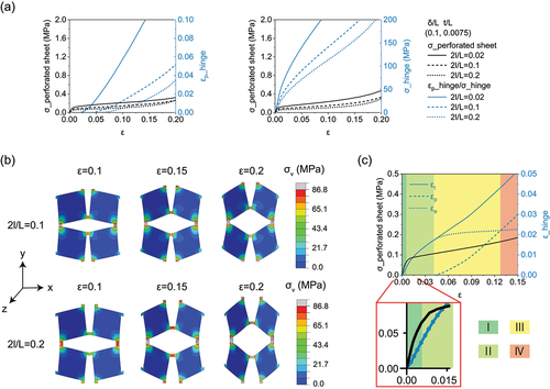
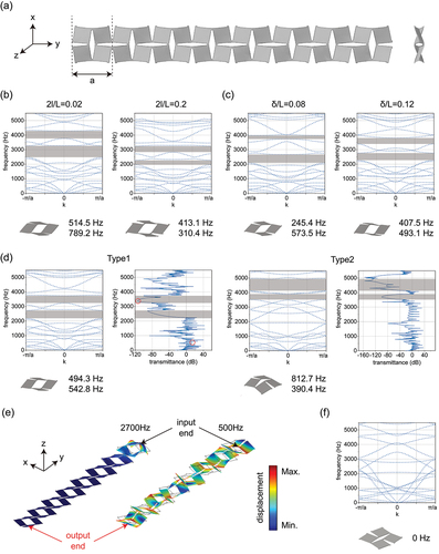
Figure 6. The numerical Bragg’s elastic wave propagation bandgaps in the periodic kirigami metamaterials. (a) The periodic kirigami metamaterial with a lattice constant of . (b) Results for the deformed structure with
. (c) Results for the deformed structure with
. (d) Results for the deformed structure with different buckling patterns with
. (e) The displacement distribution in the first-order buckling deformed finite structure corresponding to the case in (c) at 500 Hz and 2700 Hz. (f) Result for the in-plane deformed structure with
.