Figures & data
Figure 1. The blade internal cooling passages.
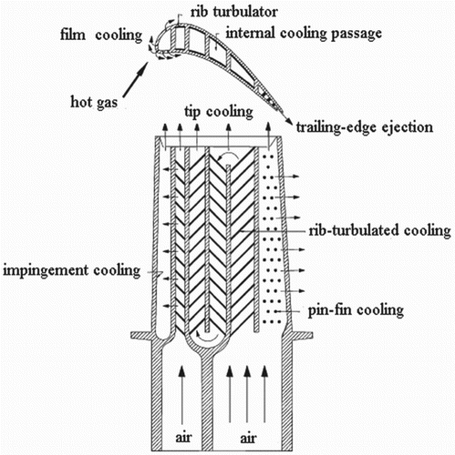
Figure 2. Models of the two-pass channels (viewed from ribbed wall to symmetric plane). (a) The arrangement of rib orientation in the U-shaped channel with 60-deg ribs; (b) Rib orientations; (c) The geometry of the model (NP case).
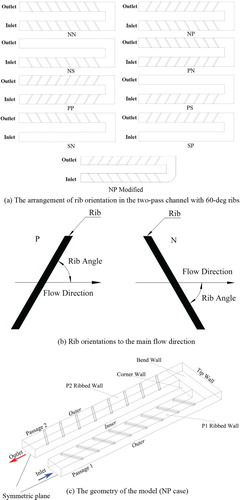
Figure 3. Mesh independency check and mesh arrangement. (a) Mesh independence check; (b) Turbulence model check; (c) Mesh details near ribs; (d) Boundary layer mesh in Passage 1 cross section.
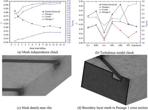
Figure 4. The centerline axis of the channel for bulk means temperature and friction factor calculation.
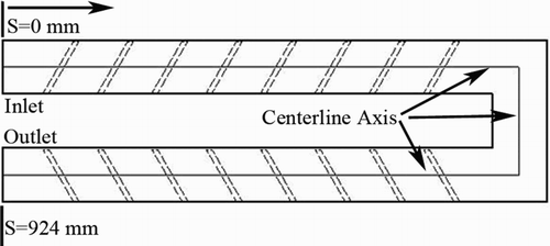
Figure 5. The experimental validation of numerical model. (a) Domain-averaged Nu ratio; (b) Friction factor in different rib orientation cases.
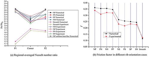
Figure 6. Nu ratio distribution with one ribbed straight passage (Re = 30000) (a) SN and SP channel; (b) NS and PS channel; (c) Smooth channel.
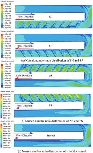
Figure 7. Nu ratio distribution with two ribbed straight passages (Re = 30000).
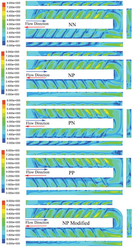
Figure 8. The overall heat convection strength of 9 different rib orientations. (Re = 30000) (a) Area-averaged Nu ratio and friction factor; (b) Thermal performance factor of 9 different rib orientations.
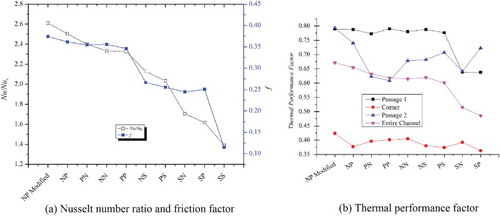
Figure 9. Regional-averaged Nu ratio in streamwise direction (Re = 30000).
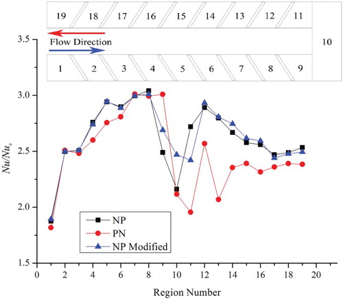
Figure 10. Secondary flow in SN and SP channel (Re = 30000; Left: SN; Right: SP).
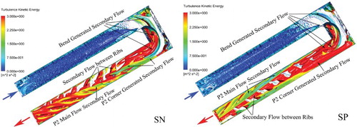
Figure 11. Secondary flow in NS and PS channel (Re = 30000). (a) The overall secondary flow distribution and shape (Left: NS; Right: PS); (b) Secondary flow vector in NS channel; (c) Secondary flow vector in PS channel.
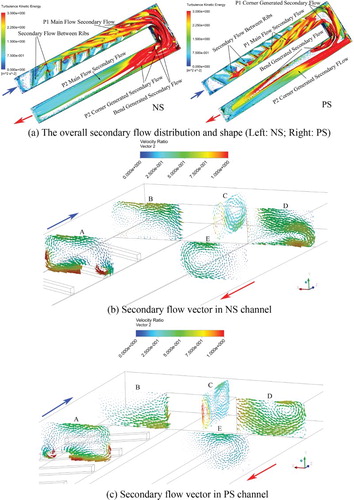
Figure 12. Secondary flow in NN and NP channel (Re = 30000). (a) The overall secondary flow distribution and shape (Left: NN; Right: NP); (b) Secondary flow vector in NP case.
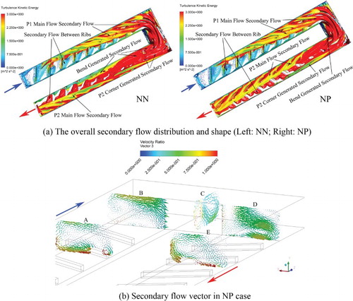
Figure 13. Secondary flow in PN and PP channel (Re = 30000). (a) The overall secondary flow distribution and shape (Left: PN; Right: PP); (b) Secondary flow vector in PN case.
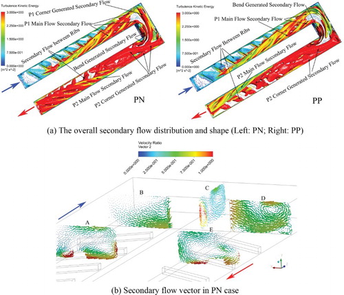
Figure 14. Secondary flow in NP modified channel (Re = 30000). (a) Secondary flow in NP modified channel; (b) Velocity vector in NP modified channel.
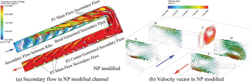
Figure 15. Secondary flow between ribs (Re = 30000); λ2 < −0.0008(−λ2)max). (a) NN; (b) NP; (c) PN; (d). PP; (e) SN; (f) SP.
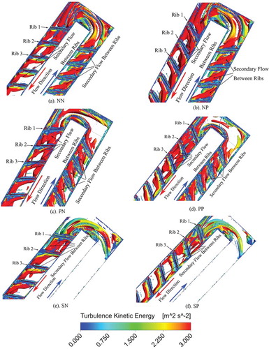
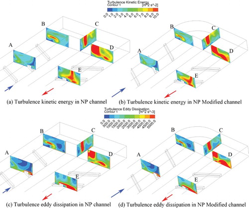
Figure 16. Turbulence kinetic energy and eddy dissipation in NP and NP Modified channel (Re = 30000). (a) Turbulence kinetic energy in NP channel; (b) Turbulence kinetic energy in NP Modified channel; (c) Turbulence eddy dissipation in NP channel; (d) Turbulence eddy dissipation in NP Modified channel.