Figures & data
Figure 1. Geometry of the real vertical pipe inlet/outlet (dimensions in m).
Figure 2. Schematic diagram of the vertical pipe inlet/outlet geometry with computational grids.
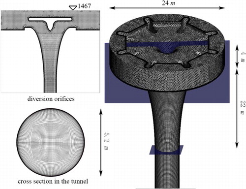
Figure 3. Comparisons of velocity distribution at the diversion orifice with different resolution grids.
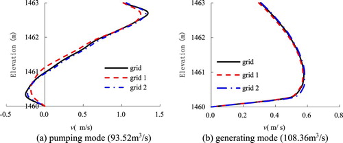
Table 1. Boundary conditions and turbulence settings applied in the simulations.
Figure 4. A view of the experimental model of the inlet/outlet made of plexiglass.
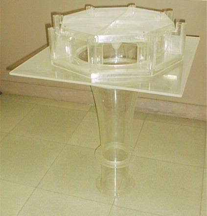
Figure 5. Schematic diagram of the experimental setup.
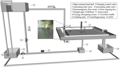
Figure 6. Head losses coefficients of simulations and experiments.
Figure 7. Correlation analysis of the head losses of experiments.
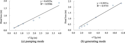
Figure 8. Correlation analysis of the head losses of simulations.

Figure 9. Velocity distribution of simulation and experiment at diversion orifice.
Figure 10. 3D velocity streamlines in the vertical outlet under pumping mode.
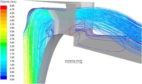
Figure 11. 3D velocity streamlines in the vertical inlet under generating mode.
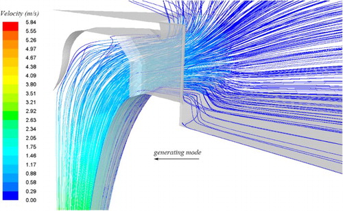
Figure 12. Head losses coefficients in different diversion orifices heights.
Figure 13. Velocity distribution at diversion orifice in different diversion orifices heights.
Figure 14. Head losses coefficients in different divergence angles.
Figure 15. Velocity distribution at diversion orifice in different divergence angles.
Figure 16. The flow pattern in the vertical pipe inlet/outlet.