Figures & data
Table 1. Engine characteristics.
Table 2. Measurement instruments specifications.
Table 3. ECE-R96 standard for testing constant speed engine.
Figure 1. Meshing combustion chamber.
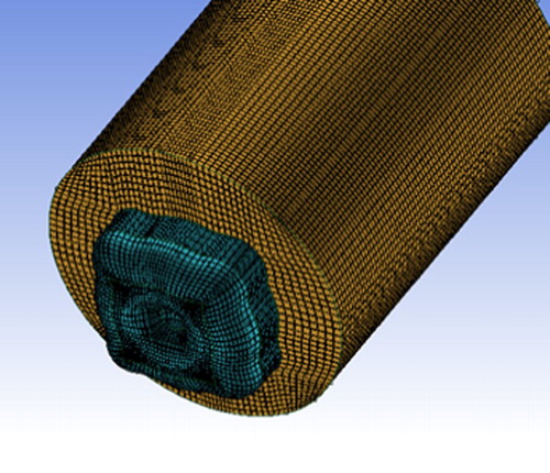
Table 4. Kinetics reactions used in simulations (Turns, Citation2000).
Table 5. Equilibrium reactions used in simulations (Turns, Citation2000).
Figure 2. The dual-fueled engine schematic.
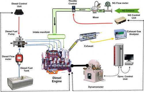
Table 6. Fuels characteristics (Iranian Research Institute of Petroleum Industry).
Figure 3. Dual-fueled engine testing in test cell.
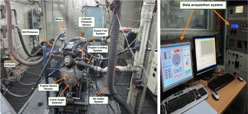
Figure 4. emission based on injection timings.
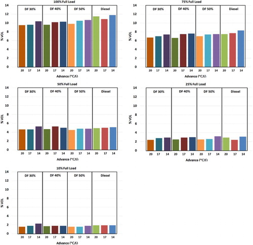
Figure 5. NOx emission for different pilot injection timings and quantities.
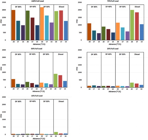
Figure 6. UHC emission for different pilot injection timings and quantities.
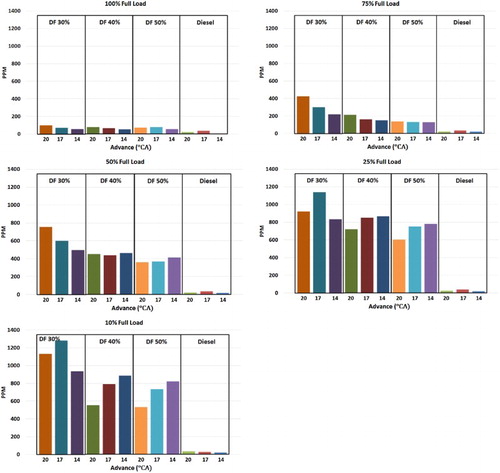
Figure 7. Lambda for different pilot injection timings and quantities.
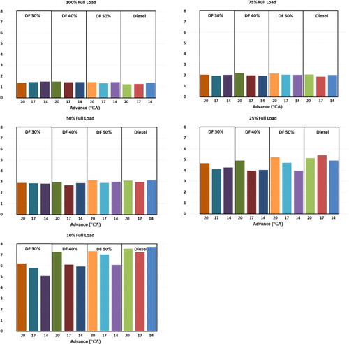
Figure 8. PM emission based on injection timings.
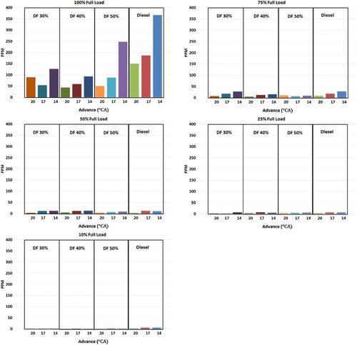
Figure 9. CO emission based on injection timings.
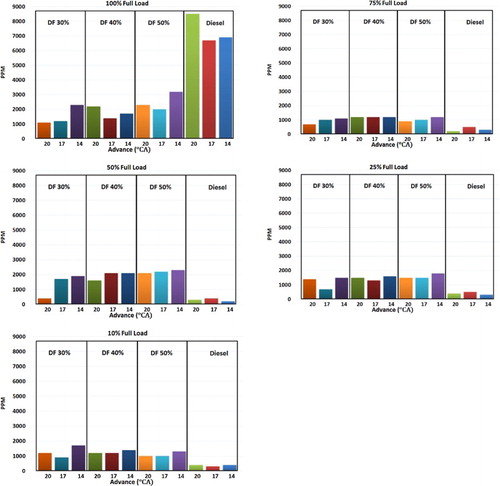
Figure 10. BSEC based on injection timings.
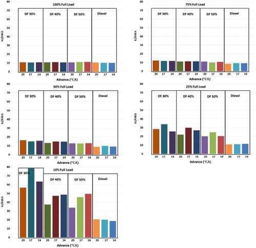
Figure 11. Cylinder pressure in full load and different advance timings, diesel mode (a), dual mode with 50% diesel (b), dual mode with 40% diesel (c), and dual mode with 30% diesel (d).
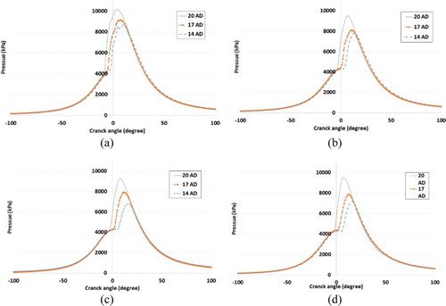
Figure 12. Experimental and simulation results of cylinder pressure in: (a) diesel mode, (b) dual mode with 50% diesel, (c) dual mode with 40% diesel, and (d) dual mode with 30% diesel.
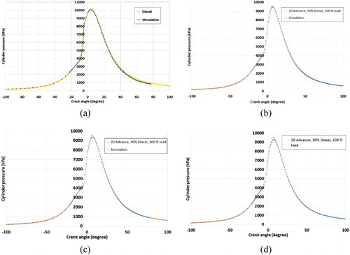
Figure 13. Simulation results for HRR and cumulative temperature in: (a) diesel mode, (b) dual mode with 50% diesel, (c) dual mode with 40% diesel, and (d) dual mode with 30% diesel.
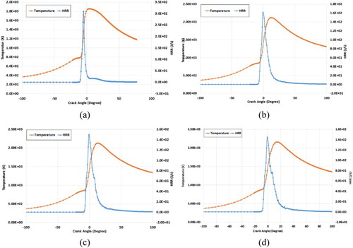
Figure 14. Simulation results for cylinder pressure at TDC for 20 degree advance timing in: (a) diesel mode, (b) dual mode with 50% diesel, (c) dual mode with 40% diesel, and (d) dual mode with 30% diesel.
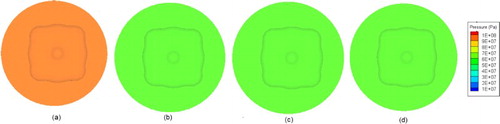
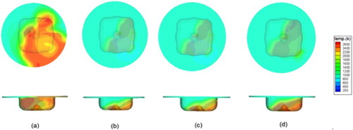
Figure 15. Simulation results for cylinder temperature at TDC for 20 degree advance timing in: (a) diesel mode, (b) dual mode with 50% diesel, (c) dual mode with 40% diesel, and (d) dual mode with 30% diesel.