
Figures & data
Figure 1. Schematic illustration representing water resource contamination by various pollutants from urban- and rural-based anthropogenic activities.
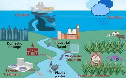
Table 1. Removal of volatile organic compounds with conventional methods
Table 2. Removal of heavy metals with conventional methods
Figure 2. Biofilter typical setup and working mechanism in the degradation of organic and inorganic pollutants present in air and wastewater.
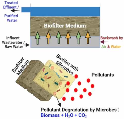
Table 3. Various biological-based processes employed in the removal of volatile organic compounds
Figure 3. Typical schematic diagram representing (a) biotrickling filter, (b) biofilter, (c) bioscrubber working principle [Citation15].
![Figure 3. Typical schematic diagram representing (a) biotrickling filter, (b) biofilter, (c) bioscrubber working principle [Citation15].](/cms/asset/bb34500f-73bf-4ad7-9af7-e8a1d4836f9f/kbie_a_2050538_f0003_b.gif)
Figure 4. Schematic diagram representing hybrid rotating drum biofilter [Citation126].
![Figure 4. Schematic diagram representing hybrid rotating drum biofilter [Citation126].](/cms/asset/3bf54350-433a-4f2d-8ca5-8a49c342565b/kbie_a_2050538_f0004_b.gif)
Figure 5. Typical submerged aerated biofilter setup for the treatment of wastewater [Citation129].
![Figure 5. Typical submerged aerated biofilter setup for the treatment of wastewater [Citation129].](/cms/asset/6e42faa4-cd44-44b3-a60f-48d7576c9e00/kbie_a_2050538_f0005_oc.jpg)
Figure 6. Schematic diagram representing the submerged aerated biofilter setup for the treatment of volatile organic compounds in pharmaceutical wastewater. (1) Magnetic stirrer, (2) Influent tank (3) Peristaltic pump, (4) Aquarium air pump, (5) Airflow meter, (6) Air inlet port, (7) Diffuser arrangement, (8) Packing media, (9) Manometer, (10) Connector for gas sampling, (11) Liquid drainage port, (12) Impinger, (13) Effluent collection tank [Citation128].
![Figure 6. Schematic diagram representing the submerged aerated biofilter setup for the treatment of volatile organic compounds in pharmaceutical wastewater. (1) Magnetic stirrer, (2) Influent tank (3) Peristaltic pump, (4) Aquarium air pump, (5) Airflow meter, (6) Air inlet port, (7) Diffuser arrangement, (8) Packing media, (9) Manometer, (10) Connector for gas sampling, (11) Liquid drainage port, (12) Impinger, (13) Effluent collection tank [Citation128].](/cms/asset/a93f7064-2d69-44b6-91cf-4050c5e94d64/kbie_a_2050538_f0006_b.gif)
Figure 7. The schematic representation of biofiltration system for the removal of low concentration nitrogen dioxide emitted from wastewater treatment plants [Citation163].
![Figure 7. The schematic representation of biofiltration system for the removal of low concentration nitrogen dioxide emitted from wastewater treatment plants [Citation163].](/cms/asset/d1c9ead9-13ae-443f-88cf-0f83183b7570/kbie_a_2050538_f0007_oc.jpg)
Figure 8. Schematic picture of aerated fixed film biofilter reactor in the treatment of hospital wastewater [Citation162].
![Figure 8. Schematic picture of aerated fixed film biofilter reactor in the treatment of hospital wastewater [Citation162].](/cms/asset/4e47df0e-1aea-4145-be05-28922b844ea8/kbie_a_2050538_f0008_oc.jpg)
Figure 9. Schematic illustration representing spray tower combined biofilter in the removal of volatile organic compounds (VOCs) present in textile dye wastewater treatment plant, which reduces the risk of respiration diseases [Citation164].
![Figure 9. Schematic illustration representing spray tower combined biofilter in the removal of volatile organic compounds (VOCs) present in textile dye wastewater treatment plant, which reduces the risk of respiration diseases [Citation164].](/cms/asset/6c678550-95ab-447d-93bc-7dc8d94b17b1/kbie_a_2050538_f0009_oc.jpg)
Table 4. Key processes adopted in the treatment of polluted stormwater [Citation184]
Table 5. Various biological-based processes employed in the removal of heavy metals in the treatment of water
Figure 10. Typical stormwater biofilter working model [Citation184].
![Figure 10. Typical stormwater biofilter working model [Citation184].](/cms/asset/89a166ed-f483-4002-bc06-7c00af2a0fcb/kbie_a_2050538_f0010_oc.jpg)
Figure 11. Diagram representing the 3D-printed monolithic biofilters based on a polylactic acid (PLA) – hydroxyapatite (HAp) biocomposite for heavy metal removal from an aqueous medium. (a) Reference PLA filter with a uniform porosity. (b) Corresponding PLA/Hap filter. (c) Reference PLA filter with gradient porosity. (d) PLA/Hap filter [Citation188].
![Figure 11. Diagram representing the 3D-printed monolithic biofilters based on a polylactic acid (PLA) – hydroxyapatite (HAp) biocomposite for heavy metal removal from an aqueous medium. (a) Reference PLA filter with a uniform porosity. (b) Corresponding PLA/Hap filter. (c) Reference PLA filter with gradient porosity. (d) PLA/Hap filter [Citation188].](/cms/asset/ebe41798-4e44-482c-8c26-7a2892faa247/kbie_a_2050538_f0011_oc.jpg)
Figure 12. Schematic illustration of amyloid fibrils coupled with activated carbon membrane as an adsorber of heavy metal ions. (a) Structure of the β-lactoglobulin protein with the strongest heavy metal-binding motif highlighted, 121-cys, with a lead ion attached. (b) Amyloid-forming 121-cys-containing fragment (LACQCL) from β-lactoglobulin with docked Pb metal ions. (c) Schematic representation of heavy metal ion purification by amyloid–carbon adsorbers, and photographs of Na2PdCl4 solution changing color from yellow to colorless after filtration due to the adsorption of palladium heavy metal ion pollutants onto the composite membrane. (d) SEM image showing the surface of the composite membrane, with the visual aspect of the membrane shown in the inset. (e) Higher-magnification SEM image of the membrane, demonstrating the assembly of the amyloid fibrils onto the activated carbon surface [Citation259].
![Figure 12. Schematic illustration of amyloid fibrils coupled with activated carbon membrane as an adsorber of heavy metal ions. (a) Structure of the β-lactoglobulin protein with the strongest heavy metal-binding motif highlighted, 121-cys, with a lead ion attached. (b) Amyloid-forming 121-cys-containing fragment (LACQCL) from β-lactoglobulin with docked Pb metal ions. (c) Schematic representation of heavy metal ion purification by amyloid–carbon adsorbers, and photographs of Na2PdCl4 solution changing color from yellow to colorless after filtration due to the adsorption of palladium heavy metal ion pollutants onto the composite membrane. (d) SEM image showing the surface of the composite membrane, with the visual aspect of the membrane shown in the inset. (e) Higher-magnification SEM image of the membrane, demonstrating the assembly of the amyloid fibrils onto the activated carbon surface [Citation259].](/cms/asset/e1eaecb3-5868-47d2-90f8-69b8be45eef1/kbie_a_2050538_f0012_oc.jpg)