Figures & data
Figure 1. (a) Scheme of the 2nd harmonic Hall measurement. An alternating current is injected along the x-direction, while the transverse 1st and 2nd harmonic Hall voltage Utrans is measured via a lock-in amplifier. In the inset an optical microscope image of the final device is depicted. (b) The hysteresis loops of Fe3GeTe2 at different temperatures with the magnetic field applied in the z direction.
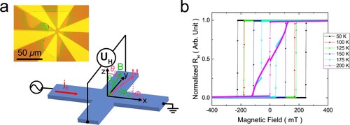
Figure 2. Examples of the 1st and 2nd harmonic Hall resistances as a function of the applied magnetic field along the x-direction Φ = 0° (a) and y-direction Φ = 90° (b) at a temperature of 100 K with a polar magnetic field angle of θB = 82°. The applied current density is 4.1 × 10¹⁰ Am−2.
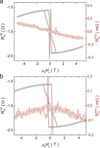
Figure 3. The derivative of the θ component of the current induced effective field is shown as a function of the externally applied magnetic field (a) and polar magnetisation angle θ0 (b) at a temperature of 175 K with a polar magnetic field angle of θB = 82°. The applied current density is 3.7 × 10¹⁰ Am−2. In (b) the data for Φ = 0° and negative applied fields has been inverted. The solid lines are fits according to equations (5) and (6).
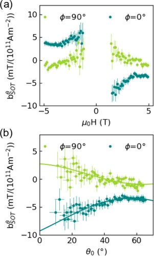
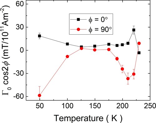
Figure 4. The extracted bulk SOT parameter Γ0*cos(2Φ) as a function of the temperature showing the opposite sign for the Φ = 0° and Φ = 90° data over the full temperature range.