Figures & data
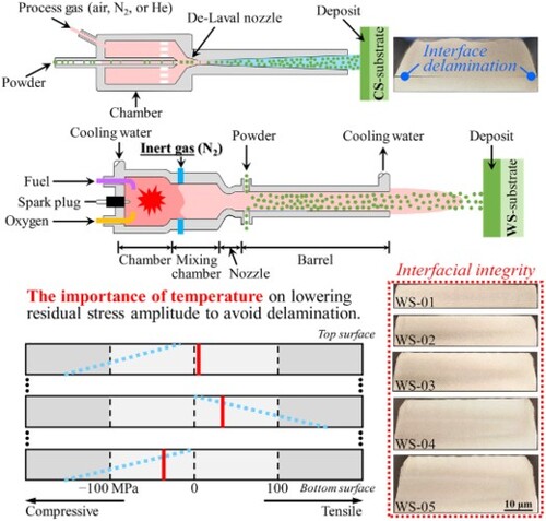
Figure 1. Schematic illustrating the differences between (a) cold spray and (b) warm spray systems [Citation20].
![Figure 1. Schematic illustrating the differences between (a) cold spray and (b) warm spray systems [Citation20].](/cms/asset/cc877dc6-60bc-4f3d-9e16-93e2a68b3723/tmrl_a_2227221_f0001_oc.jpg)
Figure 2. Delamination tends to occur when depositing (a) too thick pure Ni (Dthickness = 13.40 mm) via cold spray. Residual stress analysis for a cold-sprayed pure Ni deposit without delamination (CS-01) showing high residual stress amplitude dependent on delamination: (b) specimen photograph; (c) surface residual stresses obtained by the XRD and contour methods; (d) cross-sectional residual stress mapping through the contour method. CM refers to the contour method.
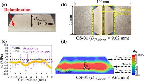
Figure 3. Specimen photographs showing no delamination of warm-sprayed pure Ni deposits with increasing thickness: (a) WS-01; (b) WS-02; (c) WS-03; (d) WS-04; (e) WS-05. Cutting positions of contour method implementation are marked with red dash-dotted lines.
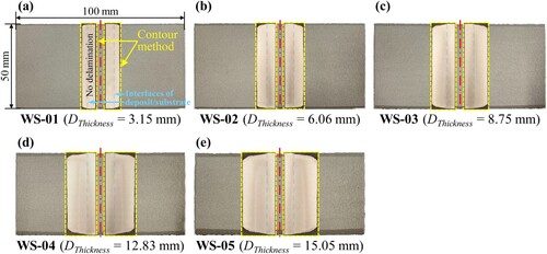
Figure 4. Residual stress analysis for warm-sprayed pure Ni deposits with increasing thickness in Figure showing the critical role of temperature in lowering residual stress amplitude to avoid delamination: (a) surface residual stresses obtained by the XRD and contour methods; (b–f) cross-sectional residual stress mapping through the contour method.
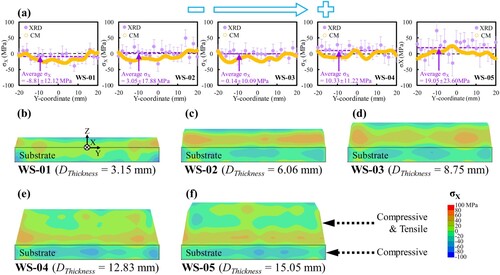
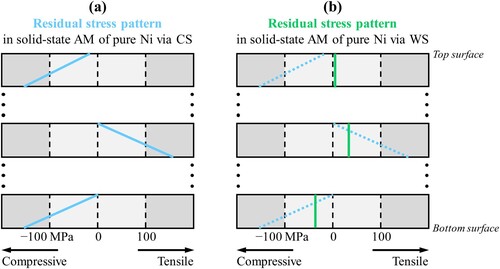
Figure 5. Schematics of the distribution pattern differences of residual stresses in solid-state additive manufacturing of pure Ni via (a) cold spray and (b) warm spray, illustrating the importance of temperature on delamination.