Figures & data
Figure 1. Characteristics of magnetic chitosan nanoparticles. (A) Transmission electron microscopy photograph of chitosan particles (×100,000). (B) Hysteresis loop of Fe3O4 nanoparticles. (C) FT-IR absorption spectra of superparamagnetic iron oxide chitosan particles.
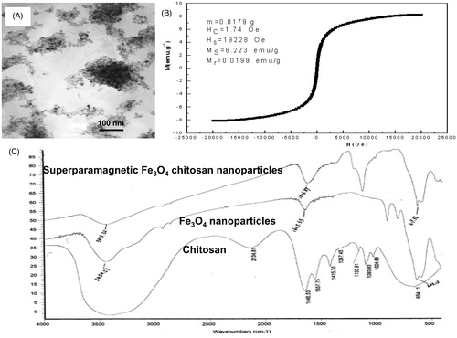
Figure 2. In vitro magnetic transfection of superparamagnetic chitosan nanoparticle complexes. (A) Plasmid binding experiment, with the marker λEcoT14 I digest. (B) Atomic force microscopy structural diagram. (C) Cell phagocytosis of the superparamagnetic chitosan plasmid complex (×1000) under a transmission electron microscope. (D) HUVEC-1 cells engulfed the superparamagnetic chitosan plasmid complexes to form endosomes (×1000). (E) MG-63 cells engulfed the superparamagnetic chitosan plasmid complexes to form endosomes (×1000). (F) Cell magnetic transfection observed under an inverted fluorescence microscope. (G) Magnetic transfection efficiency.
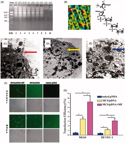
Figure 3. Study on the in vitro release of the superparamagnetic chitosan nanoparticle complex. (A) Distribution with no magnetic field. (B) Distribution under the influence of a magnetic field. (C) In vitro release curves. (D) Scanning electron microscopy results before the release. (E) Scanning electron microscopy results after the in vitro release.
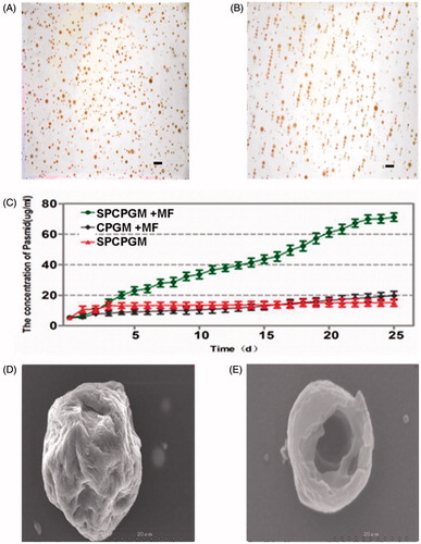
Figure 4. Plasmid concentration at different distances from the midpoint on the third day.
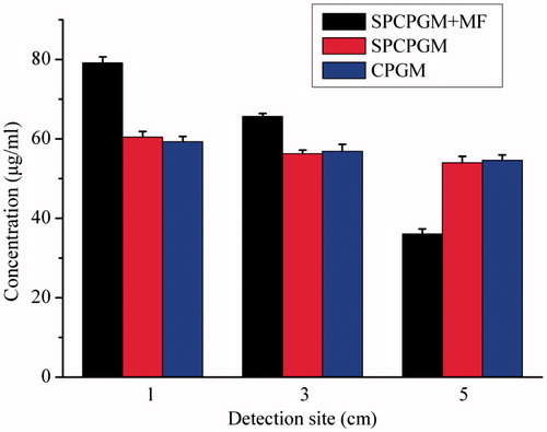
Figure 5. Repair of a radius defect in a New Zealand white rabbit with an artificial bone scaffold loaded with superparamagnetic chitosan pDsVEGF165-Red1-N1 gelatin microspheres. (A) Artificial bone scaffold (B) Artificial bone scaffold loaded with superparamagnetic chitosan pDsVEGF165-Red1-N1 gelatin microspheres. (C) The artificial bone scaffold loaded with superparamagnetic chitosan pDsVEGF165-Red1-N1 gelatin microspheres was implanted in the radial bone defect of a New Zealand rabbit. (D) General observation at 6 postoperative weeks. (E) X-ray images.
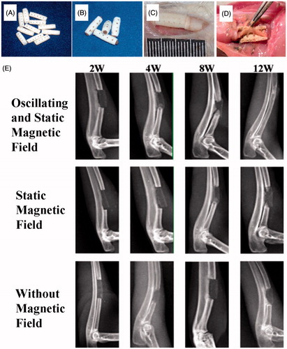
Figure 6. Repair of a radius defect in a New Zealand white rabbit with an artificial bone scaffold loaded with superparamagnetic chitosan pDsVEGF165-Red1-N1 gelatin microspheres. (A) With the effect of magnetic field and superparamagnetic chitosan pDsVEGF165-Red1-N1 gelatin microspheres, ink staining at 2 postoperative weeks. (B) Without the effect of magnetic field, ink staining at 4 postoperative weeks. (C) With the effect of superparamagnetic chitosan pDsVEGF165-Red1-N1 gelatin microspheres, ink staining at 8 postoperative weeks. (D) Postoperative ink staining pictures were analyzed by Tiger 920G image analysis software system. (E) CD31 immunohistochemical staining. (F) With the effect of magnetic field and superparamagnetic chitosan pDsVEGF165-Red1-N1 gelatin microspheres, haematoxylin and eosin (HE) staining at 8 postoperative weeks. (G) Without the effect of magnetic field, HE staining at 12 postoperative weeks. (H) Area density of the new bone tissue.
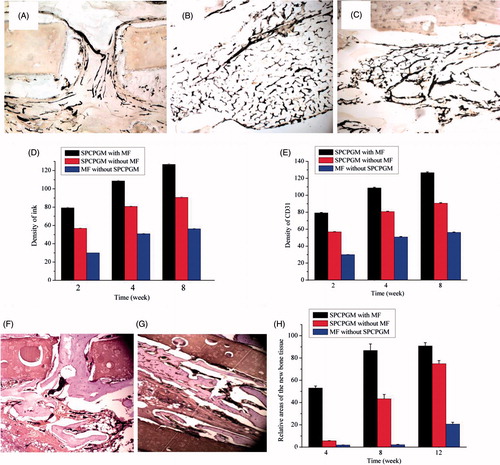
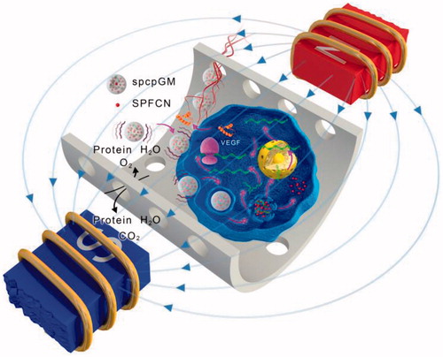
Figure 7. The mechanism of the promotion of angiogenesis and osteogenesis in the scaffold by the magnetic micro-movement and magnetic transfection of the magnetic microspheres in an oscillating magnetic field. The wave symbols indicate that the magnetic microspheres generate magnetic micro-movement in an oscillating magnetic field; the magenta arrows indicate that the magnetic field facilitates the magnetic transfection of the plasmids.