3,566
Views
33
CrossRef citations to date
0
Altmetric
Research Article

Expanded 3D nanofibre sponge scaffolds by gas-foaming technique enhance peripheral nerve regeneration

, , , , , , & show all
Pages 491-500 | Received 25 May 2018, Accepted 03 Sep 2018, Published online: 03 Apr 2019

Figures & data

Figure 1. Morphology characterization of SF/PLA 3D nanofibre scaffold (A, B). General view of SF/PLA 3D nanofibre scaffold. (C–F) SEM of SF/PLA 3D nanofibre scaffold.
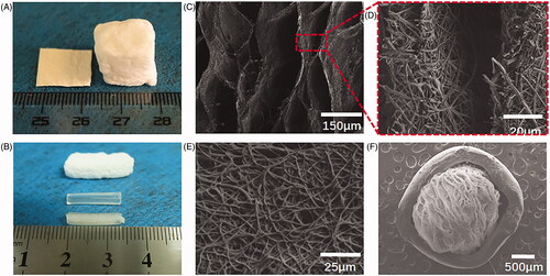
Figure 1. Morphology characterization of SF/PLA 3D nanofibre scaffold (A, B). General view of SF/PLA 3D nanofibre scaffold. (C–F) SEM of SF/PLA 3D nanofibre scaffold.

Figure 2. Expansion and characterization of the nanofibre scaffolds. (A) Thickness of the expanded PLA/SF nanofibre membranes after immersing in 0.01 M, 0.03 M, 0.01 M NaBH4 aqueous solutions for 0 min, 5 min, 15 min, 30 min and 60 min. (B) Corresponding porosities of the expanded PLA/SF nanofibre membranes after immersing in 0.01 M, 0.03 M, 0.01 M NaBH4 aqueous solutions for 0 min, 5 min, 15 min, 30 min and 60 min.
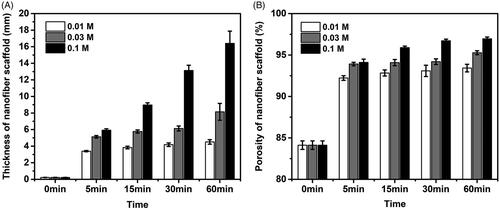
Figure 2. Expansion and characterization of the nanofibre scaffolds. (A) Thickness of the expanded PLA/SF nanofibre membranes after immersing in 0.01 M, 0.03 M, 0.01 M NaBH4 aqueous solutions for 0 min, 5 min, 15 min, 30 min and 60 min. (B) Corresponding porosities of the expanded PLA/SF nanofibre membranes after immersing in 0.01 M, 0.03 M, 0.01 M NaBH4 aqueous solutions for 0 min, 5 min, 15 min, 30 min and 60 min.

Figure 3. (A) Images of rat primary SCs cultured in medium. (B) SEM of SCs cultured in SF/PLA 3D nanofibre scaffold. (C) Date analysis of the SC proliferation with CCK8.
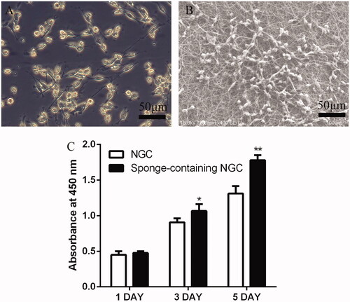
Figure 3. (A) Images of rat primary SCs cultured in medium. (B) SEM of SCs cultured in SF/PLA 3D nanofibre scaffold. (C) Date analysis of the SC proliferation with CCK8.

Figure 4. Evaluation of regenerated nerve fibres at 12 weeks after surgery. Toluidine blue-stained transverse sections (A); TEM images of the regenerated sciatic nerve (B); Density of myelinated axons (C); Diameters of myelinated axons (D); Thickness of myelin sheath (E). **p < .01 versus NGC group; #p < .05 versus SNGC group; ##p < .01 versus SNGC group.
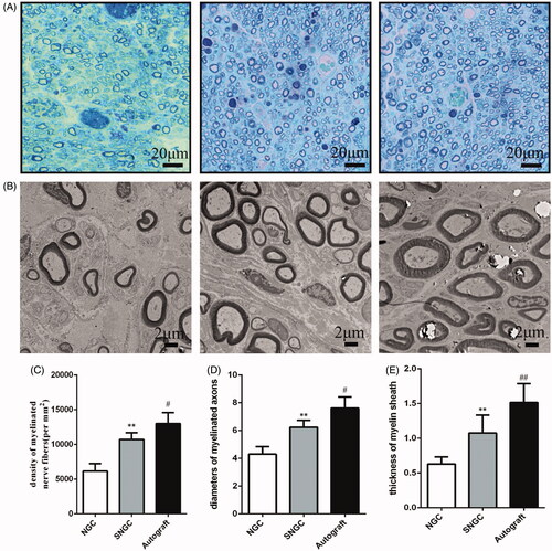
Figure 4. Evaluation of regenerated nerve fibres at 12 weeks after surgery. Toluidine blue-stained transverse sections (A); TEM images of the regenerated sciatic nerve (B); Density of myelinated axons (C); Diameters of myelinated axons (D); Thickness of myelin sheath (E). **p < .01 versus NGC group; #p < .05 versus SNGC group; ##p < .01 versus SNGC group.

Figure 5. Gastrocnemius muscle at 12 weeks after implantation. (A) Gross images of gastrocnemius muscles. (B) Masson’s trichrome staining images of the transverse sections of gastrocnemius muscles. Statistical analysis of the gastrocnemius muscle wet weight ratio (C) and cross section of muscle fibre (D). **p < .01 versus NGC group; #p < .05 versus SNGC group.
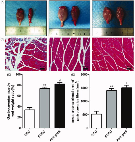
Figure 5. Gastrocnemius muscle at 12 weeks after implantation. (A) Gross images of gastrocnemius muscles. (B) Masson’s trichrome staining images of the transverse sections of gastrocnemius muscles. Statistical analysis of the gastrocnemius muscle wet weight ratio (C) and cross section of muscle fibre (D). **p < .01 versus NGC group; #p < .05 versus SNGC group.

Figure 6. Electrophysiological examinations at 12 weeks after implantation. (A) Representative CMAP recordings in each group. Statistical analysis of CMAP amplitude (B) and CMAP latency (C) detected in each group. **p < .01 versus NGC group; #p < .05 versus SNGC group.
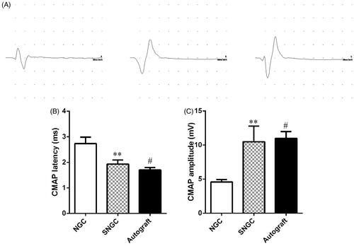
Figure 6. Electrophysiological examinations at 12 weeks after implantation. (A) Representative CMAP recordings in each group. Statistical analysis of CMAP amplitude (B) and CMAP latency (C) detected in each group. **p < .01 versus NGC group; #p < .05 versus SNGC group.

Figure 7. Motor functional recovery at 12 weeks by CatWalk gait analysis. (A) Representative CatWalk analysis trace and 3D plantar pressure distribution of RH (injured) and LH (contralateral) from three different groups. Statistical analysis of the mean stand time ratio (B) and SFI values (C). **p < .01 versus NGC group; #p < .05 versus SNGC group; ##p < .01 versus SNGC group.
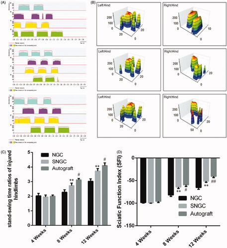
Figure 7. Motor functional recovery at 12 weeks by CatWalk gait analysis. (A) Representative CatWalk analysis trace and 3D plantar pressure distribution of RH (injured) and LH (contralateral) from three different groups. Statistical analysis of the mean stand time ratio (B) and SFI values (C). **p < .01 versus NGC group; #p < .05 versus SNGC group; ##p < .01 versus SNGC group.
Supplemental material

Responses_to_reviewers.docx

Download ()