
Figures & data
Figure 1. Vertical ground reaction force of one CMJ trial and phases determined by jump initiation (FSTART), take-off (TO) and landing
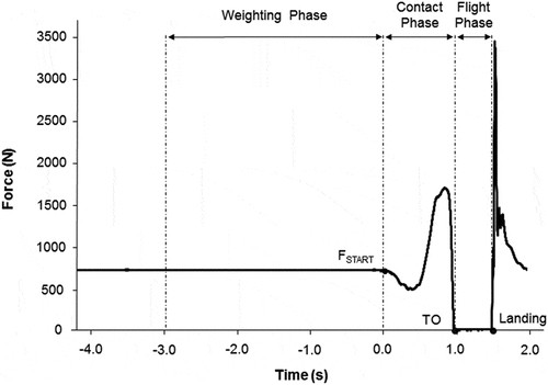
Figure 2. Performance measurements derived from vertical ground reaction force during the contact phase. Key inflection points indicate the minimum force (FMIN), the minimum velocity (VMIN) and the maximal downward amplitude (DMAX). Peak force (PF), peak power (PP), and peak velocity (PV) indicate the maximum values registered in a given curve, minimum power (PMIN) is the lowest value (peak negative value) of the power-time curve and (VPP) is the velocity achieved at the point where PP occurred. Power and displacement scales have been omitted
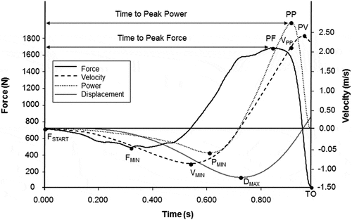
Figure 3. Different approaches to determine countermovement jump sub-phases based on: (a) force-time curve, where minimum force delimits the decreasing force time (TFDEC) and the increasing force time (TFINC), (b) displacement- or power-time curves, where the downward displacement time (TDDEC) is measured, (c) velocity-time curve, where FBRAKE is the point in the force curve at minimum velocity, FPROP is the point in the force where velocity turns into positive values and TBRAKE-PF is the time from the initiation of the braking sub-phase to peak force, and (d) force- and displacement-curve
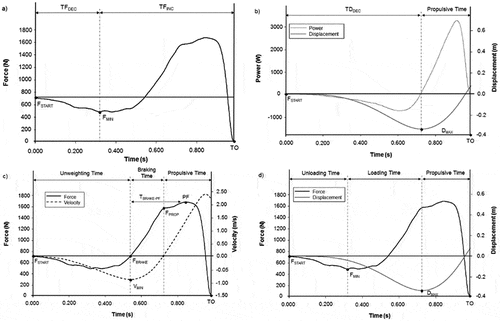
Figure 4. Determination of the transition sub-phase that represents the zone included between the first and second inflection points
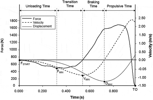
Table 1. Contact phase variables, abbreviations, and descriptions
Figure 5. Ratios of force development of the unloading sub-phase (RFDUNLOAD), the loading sub-phase (RFDLOAD), the transition sub-phase (RFDTRANSITION), the braking sub-phase (RFDBRAKE), and the ratio of force development from the initiation of the braking sub-phase to peak force (RFDBRAKE-PF)
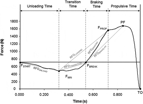
Table 2. Key Points: data description, mean differences between sessions, and reliability of measures
Table 3. Flight phase
Table 4. Contact phase
Table 5. Propulsive sub-phase
Table 6. Sub-phases based on the force curve
Table 7. Sub-phases based on the displacement curve
Table 8. Sub-phases based on velocity-time curve
Table 9. Sub-phases based on force- and displacement-time curves
Table 10. Transition sub-phase