5,590
Views
5
CrossRef citations to date
0
Altmetric
Review Article

Friction-loaded cycle ergometers: Past, present and future

& | (Reviewing Editor)
Article: 1029237 | Received 30 Nov 2014, Accepted 09 Mar 2015, Published online: 13 Apr 2015

Figures & data

Figure 1. Force acting on the tight (FT) and slack (FS) ends of a rope winding around a rotating cylinder.
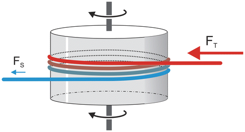
Figure 1. Force acting on the tight (FT) and slack (FS) ends of a rope winding around a rotating cylinder.

Figure 2. Braking mechanism of the first friction-loaded ergometers; braking force acting on the flywheel (FFW) is equal to the difference between tight (FT) and slack (FS) forces which were displayed by means of scale.
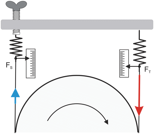
Note: Pedal rate, FT, and FS had to be continuously recorded or adjusted to know the actual work.
Figure 2. Braking mechanism of the first friction-loaded ergometers; braking force acting on the flywheel (FFW) is equal to the difference between tight (FT) and slack (FS) forces which were displayed by means of scale.

Figure 3. Amar’s cycle ergometer; D, P, and R correspond to the dynamometer, platform for weight, and steel ribbon, respectively.
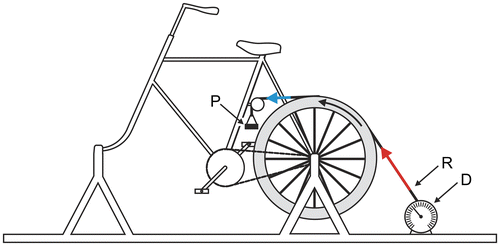
Note: Red and blue arrows correspond to FT and FS, respectively.
Figure 3. Amar’s cycle ergometer; D, P, and R correspond to the dynamometer, platform for weight, and steel ribbon, respectively.

Figure 4. Thomson brake (drawing adapted from Beaumont, Citation1889, p. 33; Jervis-Smith, Citation1915, p. 82).
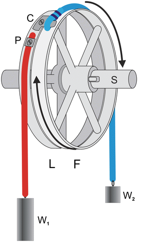
Notes: L corresponds to the loose pulley and F to the fast pulley, rigidly fixed to shaft S; P: fixation of the tight rope (in red). C: connection between the loose pulley and the rope (in blue) rubbing on the fast pulley.
Figure 4. Thomson brake (drawing adapted from Beaumont, Citation1889, p. 33; Jervis-Smith, Citation1915, p. 82).

Figure 5. Fleisch ergometer; F et L fast et loose wheels, C connection between pulley L and belt B that is attached to weight W2 at the other end.
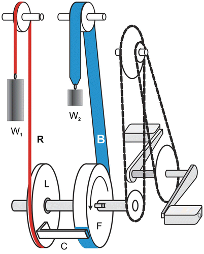
Notes: FT and FS are equal to W1 and W2, respectively. For clarity, the distance between L and F has been increased.
Figure 5. Fleisch ergometer; F et L fast et loose wheels, C connection between pulley L and belt B that is attached to weight W2 at the other end.

Figure 6. A, LB et LP arms of forces FB and P; FT and FS, tensions of the tight and slack ends of the belt; O1, O2, and O3, axles of the flywheel, cam, and pulley, respectively; O4 pivot of the roman steelyard; B, h1, and h2 lever-arms of FS1 and FS2, respectively; Wc and hc weight of the cam and its lever arm.
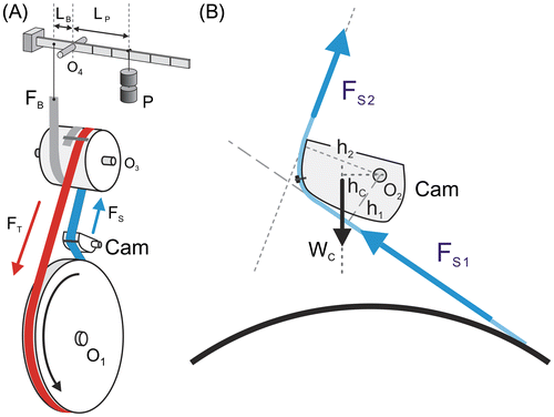
Figure 6. A, LB et LP arms of forces FB and P; FT and FS, tensions of the tight and slack ends of the belt; O1, O2, and O3, axles of the flywheel, cam, and pulley, respectively; O4 pivot of the roman steelyard; B, h1, and h2 lever-arms of FS1 and FS2, respectively; Wc and hc weight of the cam and its lever arm.

Figure 7. Von Döbeln ergometer.
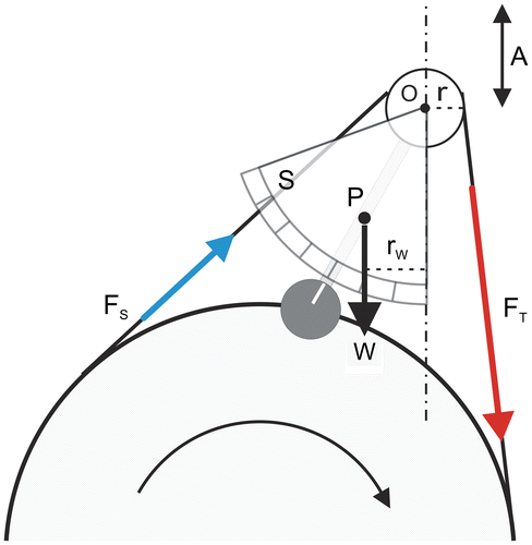
Note: P center of mass of the pendulum, S force scale, O axle of the pulley.
Figure 7. Von Döbeln ergometer.

Figure 8. Monark sinus-balance cycle ergometer.
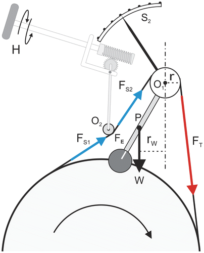
Notes: O1, axle of the sinus-balance pulley, O2, axle of the pulley pressing on the slack belt; W, P, and rW, weight, center of gravity, and arm lever of the pendulum; FT and FS tension of the tight and slack ends; FSC, tension of the slack belt corrected by the force FE exerted by the pulley; H, handle for manual adjustment of braking torque. The force scale is not presented; S2 secondary force scale readable by the subject who pedals.
Figure 8. Monark sinus-balance cycle ergometer.

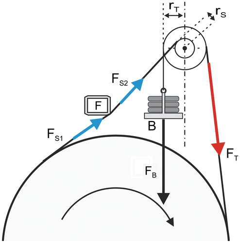
Figure 9. Weight-basket loaded cycle ergometer.
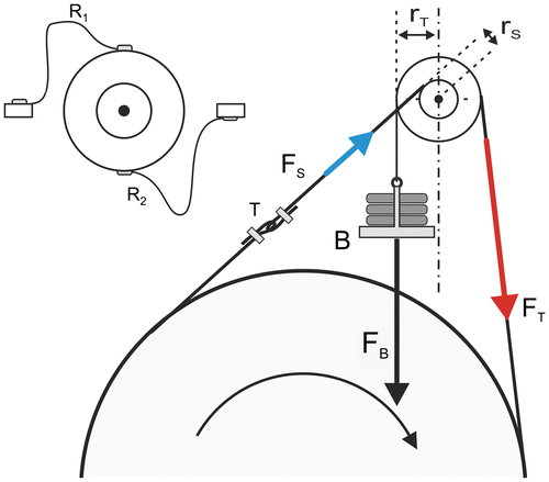
Notes: Radius rS is smaller than radius rT. R1 and R2, ribbons limiting the vertical displacements of the basket. FB, FT, and FS, forces exerted on the pulley by the basket load, the tight, and slight extremities of the belt-rope, respectively; T turnbuckle.
Figure 9. Weight-basket loaded cycle ergometer.

Figure 10. A, belt in the sinus-balance model; B, belt and rope in the basket-loaded ergometers; C, digging of small grooves in the circumference of aluminum flywheel; D, 3-turn rope.
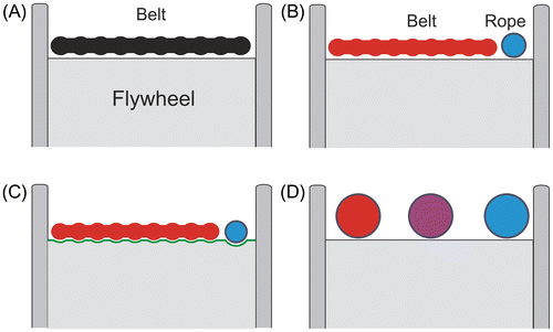
Note: In red and blue, tight and slack extremities, respectively.
Figure 10. A, belt in the sinus-balance model; B, belt and rope in the basket-loaded ergometers; C, digging of small grooves in the circumference of aluminum flywheel; D, 3-turn rope.

Figure 11. Relationships between μ, FT, FS, and error in FFW expressed as fractions of FB.
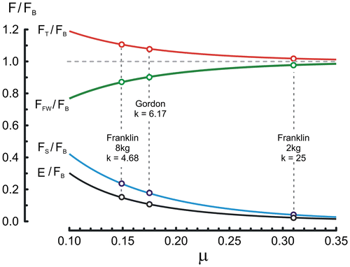
Notes: Data computed for θ = 10.4 rad and rS/rT = 0.45. The data corresponding to the studies by Gordon et al. (Citation2004) and Franklin et al. (Citation2007) have been added with the values of k corresponding to ratio FT/FS.
Figure 11. Relationships between μ, FT, FS, and error in FFW expressed as fractions of FB.

Figure 12. In A, time–frequency curves during all-out sprints against different loads on a Monark 864 cycle ergometer; in B, relationship between load and peak frequency (Vpeak).
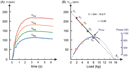
Note: The parabola in B corresponds to the load–power output relationship computed from the linear load–Vpeak relationship (Pmax = 0.25 V0F0). Adapted from Driss & Vandewalle (Citation2013).
Figure 12. In A, time–frequency curves during all-out sprints against different loads on a Monark 864 cycle ergometer; in B, relationship between load and peak frequency (Vpeak).

Figure 13. Time–power output curves computed during all-out sprints on basket-loaded cycle ergometer against loads equal to 19 N (red curve) and 76 N (blue curve).
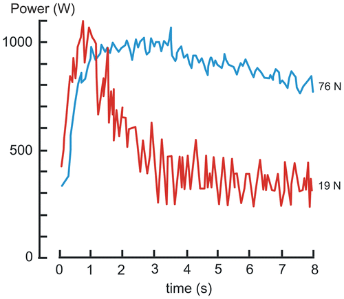
Note: Adapted from Driss & Vandewalle (Citation2013).
Figure 13. Time–power output curves computed during all-out sprints on basket-loaded cycle ergometer against loads equal to 19 N (red curve) and 76 N (blue curve).

Figure 14. Relationship between the computed torque exerted on the crankwheel and crank angular speed (or pedal rate) during all-out sprints against two loads (19 N red points and 76 N blue points) in the same subject.
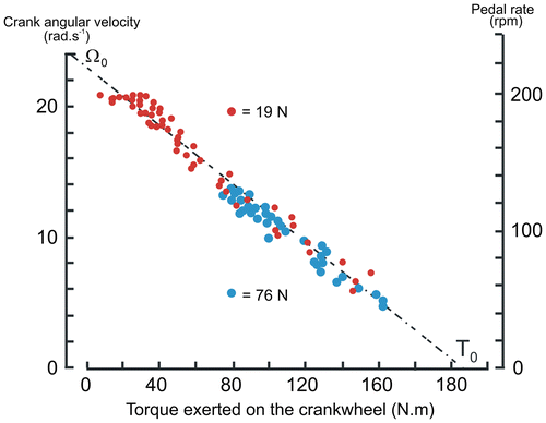
Note: Data adapted from Seck et al. (Citation1995), with permission.
Figure 14. Relationship between the computed torque exerted on the crankwheel and crank angular speed (or pedal rate) during all-out sprints against two loads (19 N red points and 76 N blue points) in the same subject.

Figure 15. In A, adjustment of the zero; in B, force calibration with a calibrated weight.
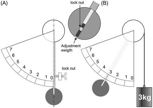
Note: The position of the pendulum can be adjusted by deplacing the adjustement weight.
Figure 15. In A, adjustment of the zero; in B, force calibration with a calibrated weight.

Figure 16. Contact of the frame (F) with the slack extremity of the belt-rope.

Figure 16. Contact of the frame (F) with the slack extremity of the belt-rope.

Figure 17. In A decomposition of the force F1 exerted on the pedal into a force F2 exerted on the crank shaft and a couple C; in B comparison of the mean torque (red line) and the torques exerted on the left (blue dashed line, L) and right crank (blue continuous line, R) during a pedal revolution.
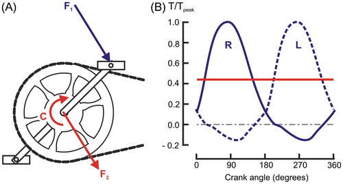
Figure 17. In A decomposition of the force F1 exerted on the pedal into a force F2 exerted on the crank shaft and a couple C; in B comparison of the mean torque (red line) and the torques exerted on the left (blue dashed line, L) and right crank (blue continuous line, R) during a pedal revolution.

Figure 18. Schematic diagram of the method used in the study by Jones & Passfield (Citation1998) for the comparison of a basket-loaded MonarkTM ergometer (in blue), model 814 (ME) and data of different SRMTM transducers.
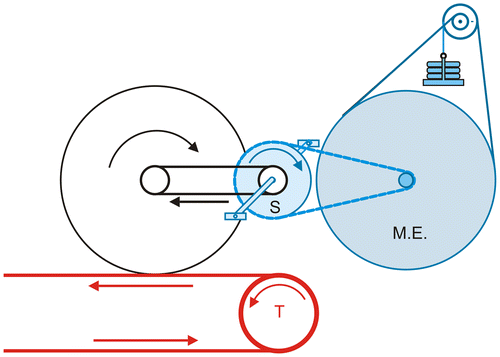
Notes: The SRMTM transducer crank wheel (S) was driven by a chain from a bicycle wheel driven by a treadmill (T, in red) belt. The SRMTM crank wheel, in turn, drove the flywheel of the MonarkTM ergometer.
Figure 18. Schematic diagram of the method used in the study by Jones & Passfield (Citation1998) for the comparison of a basket-loaded MonarkTM ergometer (in blue), model 814 (ME) and data of different SRMTM transducers.

Figure 19. Results of dynamic calibrations of friction-loaded ergometers.
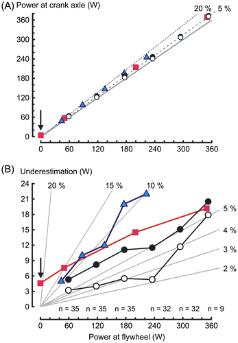
Notes: (A) Comparison of the power output according to the manufacturer (power at flywheel) and power output measured by dynamic calibration; continuous line corresponds to identity line, dotted, and dashed lines error levels equal to 5 and 20%, respectively. (B) Differences between power output a flywheel and calibrated power at crank axle, gray lines correspond to different levels of underestimation (% of power output at flywheel). In red, Cumming & Alexander (Citation1968), mean of 4 Monark ergometers; in blue, Wilmore et al. (Citation1982), 1 ergometer; black points, Maxwell et al. (Citation1998), mean of 35 Monark ergometers, protocol with increasing power output; empty circles, Maxwell et al. (Citation1998), mean of 35 Monark ergometers, protocol with decreasing power output.
Figure 19. Results of dynamic calibrations of friction-loaded ergometers.

Figure 20. Parts of a cycle ergometer that must be maintained (explanations in text); 7, chain adjuster bolt, lateral view.
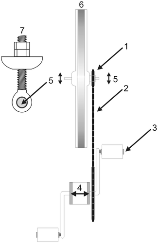
Figure 20. Parts of a cycle ergometer that must be maintained (explanations in text); 7, chain adjuster bolt, lateral view.

Figure 21. Example of a mechanism enabling the adjustment of the belt tension by a change in distance between the axes of the pulley (O1) and the flywheel; O2, axle of the mechanism; H, handle; N, locking nut.
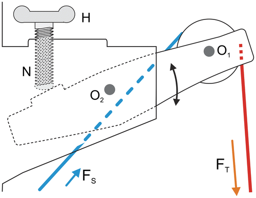
Figure 21. Example of a mechanism enabling the adjustment of the belt tension by a change in distance between the axes of the pulley (O1) and the flywheel; O2, axle of the mechanism; H, handle; N, locking nut.

Figure 22. Braking mechanism consisting of a friction belt made of two belts in series; in red, belt with low friction coefficient (μ1); in blue, belt with high friction-coefficient (μ2).
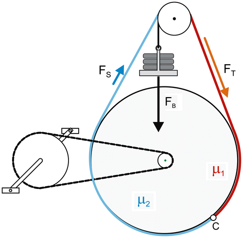
Note: C, connection between the belts.
Figure 22. Braking mechanism consisting of a friction belt made of two belts in series; in red, belt with low friction coefficient (μ1); in blue, belt with high friction-coefficient (μ2).

Figure 23. Variation of the location of the center of mass during half a revolution of the flywheel.
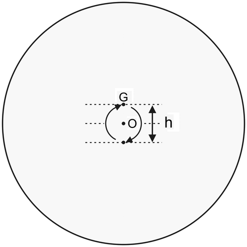
Figure 23. Variation of the location of the center of mass during half a revolution of the flywheel.

Figure 24. Relationship between ratio μ1/μ2 and descent (D) of the basket from a basket weight equal to 2 kg to a weight equal to 8 kg.
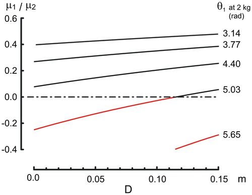
Notes: These curves have been computed for a decrease in k from 25 (FB = 19.6) to 4.28 (FB = 78.5 N). Ratio μ1/μ2 was computed for values of θ1 (winding of the belt around the flywheel) ranging between 3.14 and 5.7 rad (0.5 ≤ h2 ≤ 0.9) with a basket weight equal to 2 kg. In red, negative values.
Figure 24. Relationship between ratio μ1/μ2 and descent (D) of the basket from a basket weight equal to 2 kg to a weight equal to 8 kg.