Figures & data
Figure 1. The schematic layout of work-piece and tool.
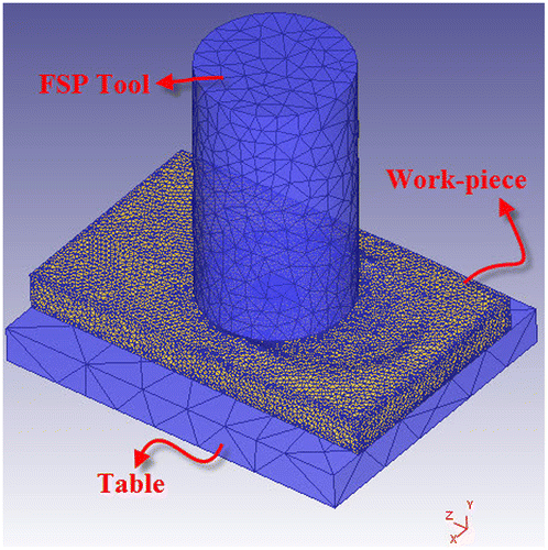
Figure 2. The stress–strain curves of pure nylon 6 at different temperatures for strain rate of (a) 0.33 × 10⁻³; (b) 1.67 × 10⁻³; (c) 3.33 × 10⁻³; (d) 1.67 × 10⁻².
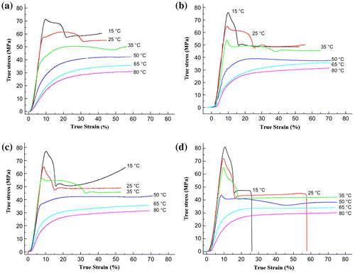
Table 1. Thermal properties of the work-piece and FSP tool, and back-plate
Table 2. The FSP parameters used in the simulation procedure and actual FSP experiment
Figure 3. The macro-surface appearance of the specimen fabricated by the optimum combination of 2,000 rpm for rotational speed and 100 mm/min for traverse speed.
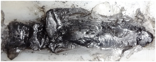
Figure 4. XRD patterns of pure nylon 6 and the specimen fabricated with the optimum combination of FSP parameters.
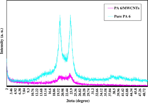
Figure 5. The XRD patterns of pure MWCNTs.
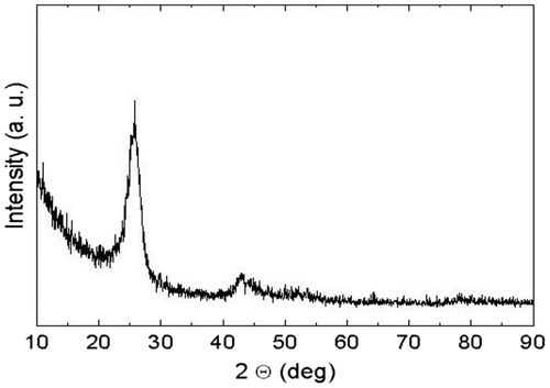
Figure 6. The MWCNTs observed by SEM.
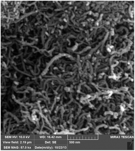
Figure 7. The homogenous dispersion of MWCNTs in matrix of nylon 6 fabricated in 2,000 rpm of rotational speed and 100 mm/min of traverse speed.
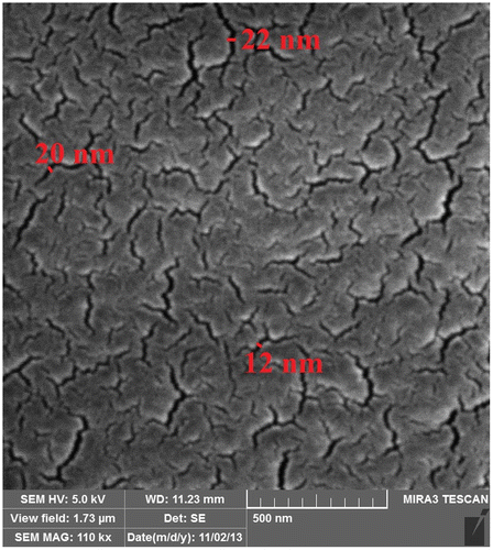
Figure 8. The temperature histories of a point located 5 mm away from the FSP center line.
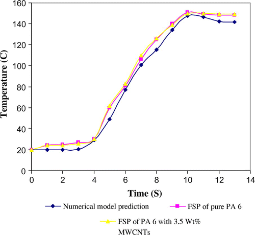
Figure 9. The temperature contours along the tool path after 18 mm tool feed (a) at surface; (b) in midline cross section; (c) in bulk.
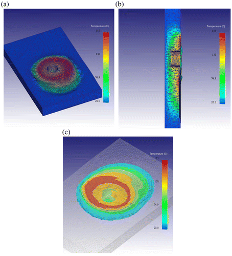
Figure 10. The schematic location of selected points for temperature history analysis.
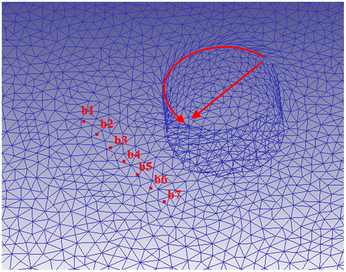
Figure 11. The temperature history of selected points located at advancing and retreating side of work-piece.
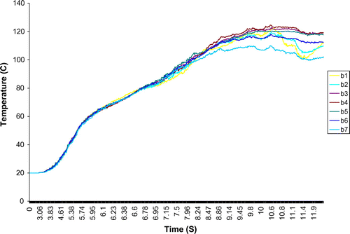
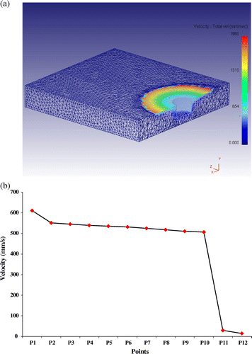
Figure 12. The schematic layout of points selected for flow study during the FSP.
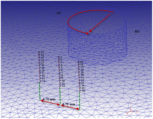
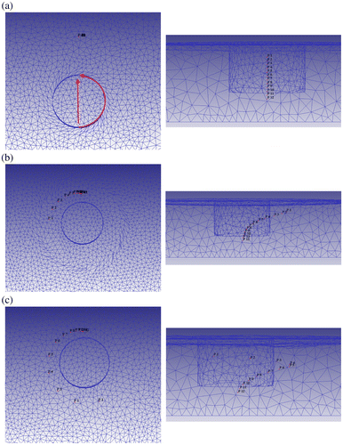
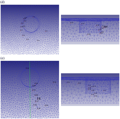
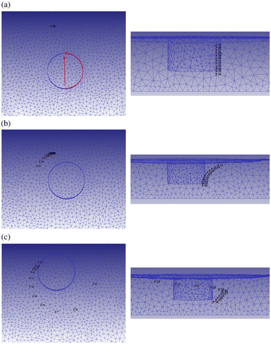
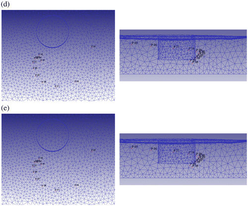
Figure 16. General view of flow pattern for pure nylon 6.
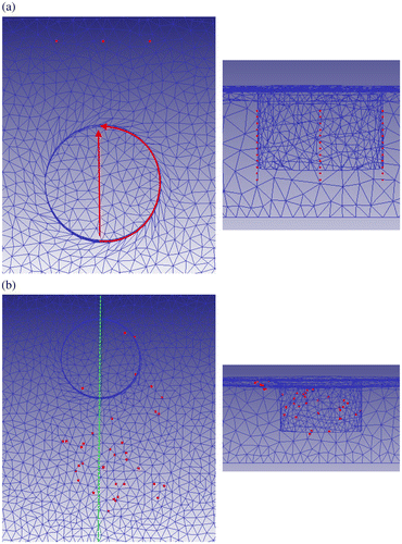
Figure 17. The cross section of stirred zone for (a) pure nylon 6; (b) mixture of nylon 6/MWCNTs.
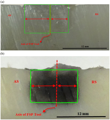
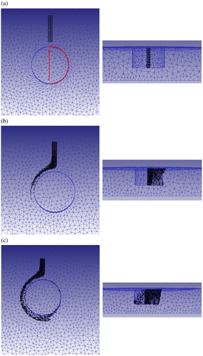
Figure 19. The effective plastic strain counters along the tool path after 18 mm tool feed.
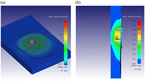
Figure 20. The historic curves of effective plastic strain for points (a) P1–P12; (b) P13–P24; (c) P25–P36.
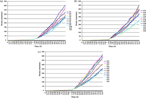
Figure 21. (a) The velocity pattern of material; (b) velocity of points P1–P12.