
Figures & data
Figure 1. The single link robotic PAM arm
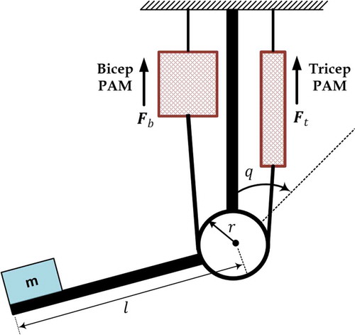
Figure 2. Schematic diagram of observer-based STSMC PAM manipulator
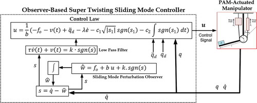
Table 1. List of parameters assigned to PSO algorithm
Figure 3. Open-loop response for the Single-Arm Manipulator
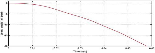
Table 2. The robotic arm parameters
Table 3. The optimal values of design parameters for SMO-STSMC and STSMC based on the PSO algorithm
Figure 4. Evolution of the objective function versus the iterations using SMO-STSMC
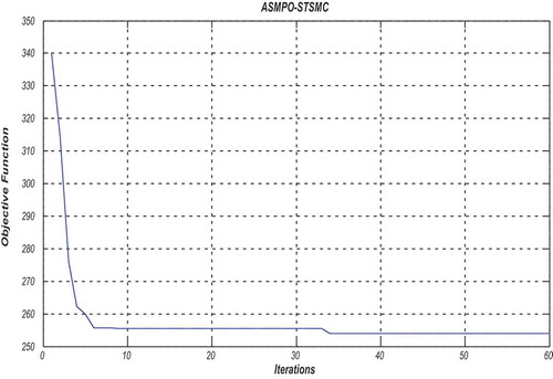
Figure 5. Evolution of the optimized parameters (,
and
) versus iterations.
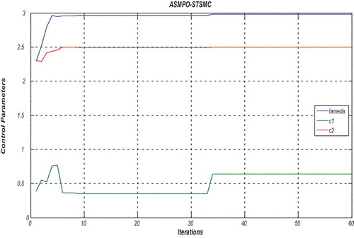
Figure 6. Evolution of the optimized parameters ( and
) versus the iterations.
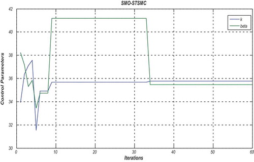
Figure 7. Evolution of the optimized
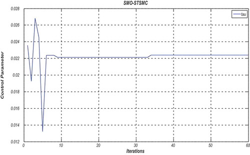
Figure 8. Evolution of the objective function versus the iterations by using STSMC
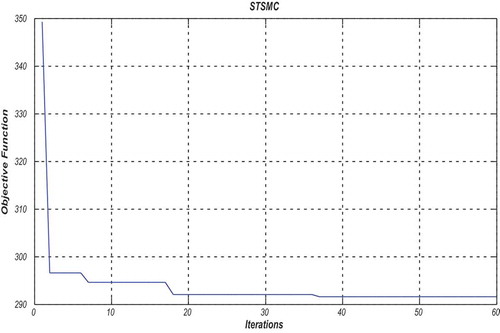
Figure 9. Evolution of the optimized parameters (,
, and
) versus iterations.
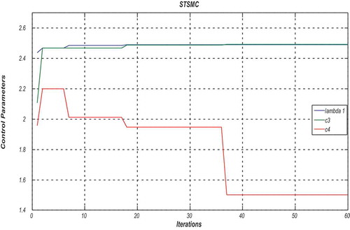
Figure 10. Angle response without uncertainty
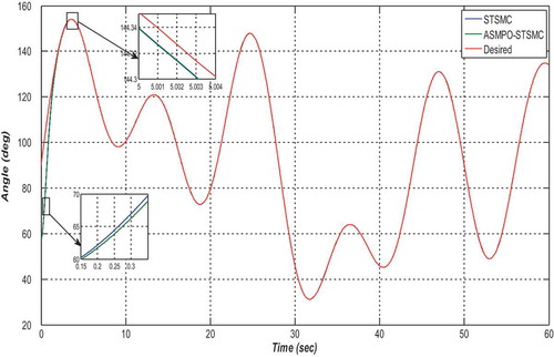
Figure 11. Angular velocity without uncertainty
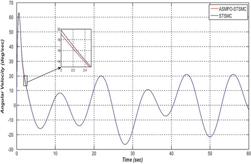
Figure 12. Control action without uncertainty
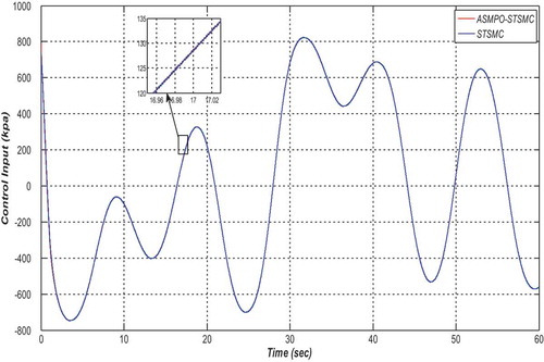
Figure 13. Angle error signal without uncertainty
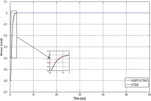
Figure 14. Surface variable without uncertainty
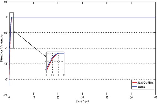
Figure 15. Estimated uncertainty without uncertain
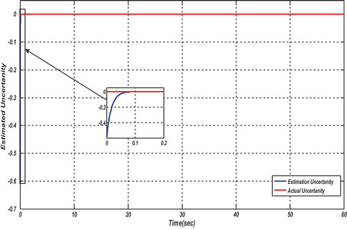
Figure 16. Angle response with 5% uncertainty in parameters
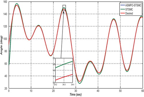
Figure 17. Angular velocity response with 5% uncertainty in parameters
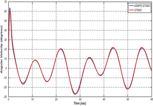
Figure 18. Control action with 5% uncertainty in parameters
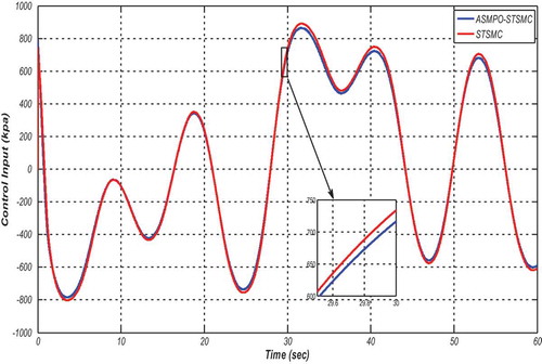
Figure 19. Angle error signal with 5% uncertainty in parameters
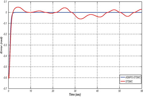
Figure 20. Surface curve with 5% uncertainty in parameters
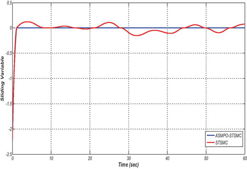
Figure 21. Estimated uncertainty with 5% uncertainty in parameters
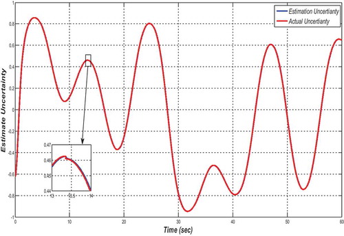
Figure 22. Angle response under disturbance
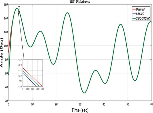
Figure 23. Angular velocity response under disturbance
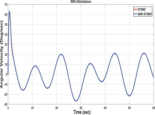
Figure 24. Control signals due to both controllers
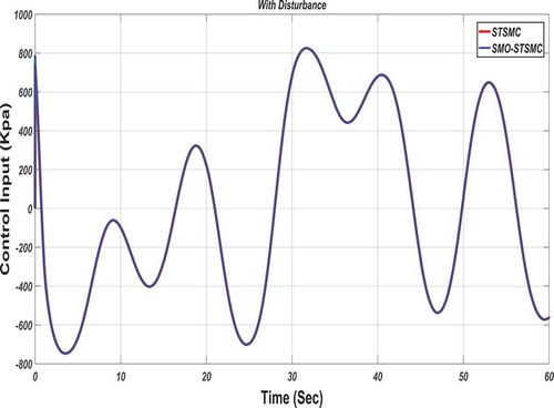
Figure 25. The error responses due to both controllers (Under disturbance)
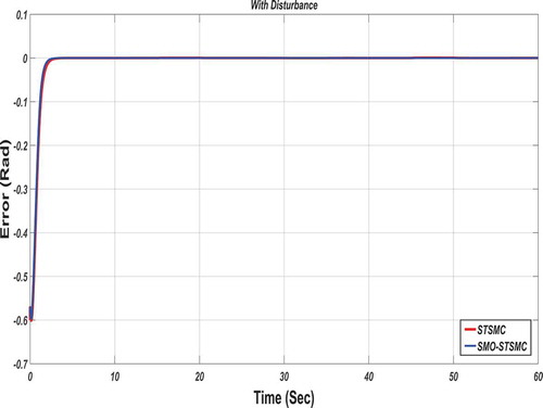
Figure 26. Responses of Sliding Variables
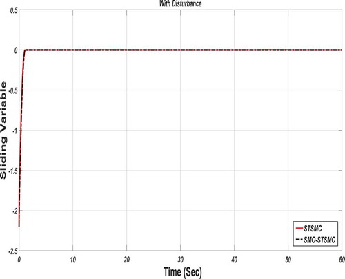
Figure 27. Disturbance Estimation
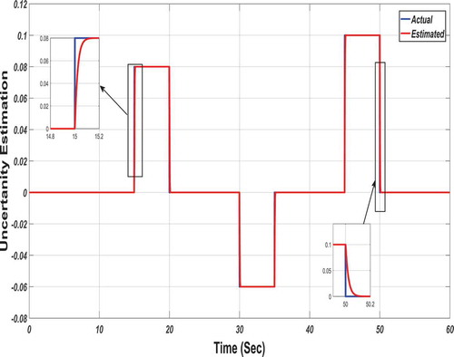
Figure 28. Angle response (with combined effect)
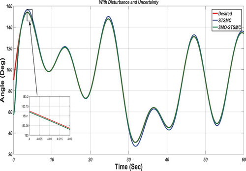
Figure 29. Angular velocity response (with combined effect)
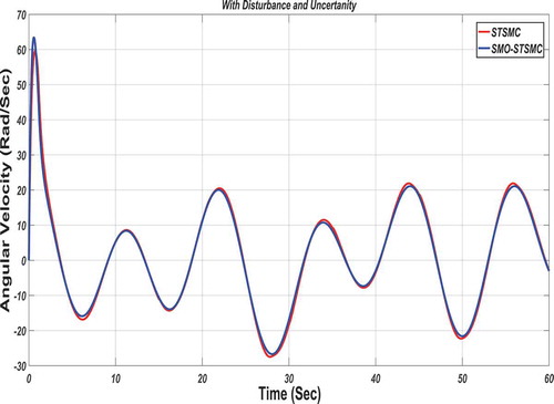
Figure 30. Control signals due to both controllers (with combined effect)
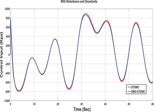
Figure 31. The error responses due to both controllers (with combined effect)
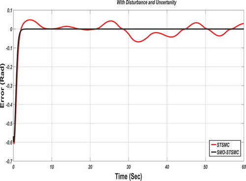
Figure 32. Responses of Sliding Variables
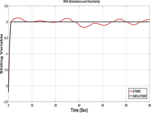
Figure 33. Disturbance-Uncertainty Estimation
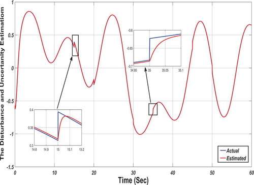
Table 4. The numerical reports of the dynamic performance of proposed controllers