Figures & data
Figure 1. Configuration of common bumper (Lee et al., Citation2009)
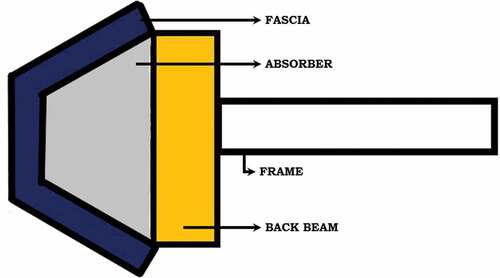
Figure 2. NCAP level for low-speed frontal impact (Hs, Citation2007)
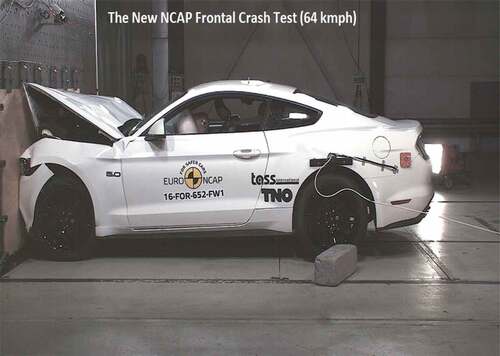
Figure 3. The nomenclature of the honeycomb (Thomas & Tiwari, Citation2019)
Figure 4. The original model of passenger vehicle frontal bumper
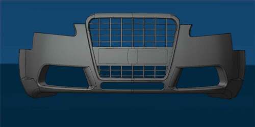
Figure 5. Design of perforated conceptual design of the car bumper
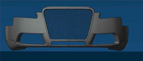
Figure 6. (a) Mesh independency graph. Variation of the stress values with a change in mesh size is illustrated. (b) Meshed bumper with a rigid wall
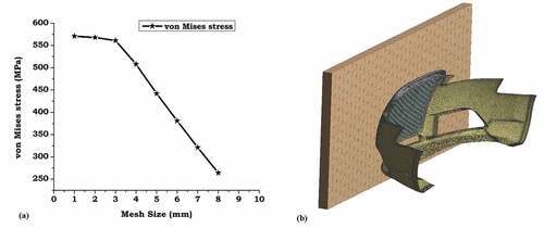
Table 1. Mechanical properties of aluminium alloy 5052 (Bhowmik & Srivas AK, Citation2016)(Bhowmik & Mishra, Citation2018)
Figure 7. (a) Equivalent Stress on the frontal fascia, (b) equivalent Stress on the outer case, (c) equivalent Stress on the honeycomb structure and (d) equivalent stress on the entire bumper (2 mm thickness)
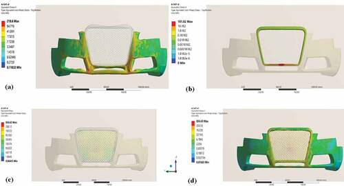
Table 2. Equivalent stress values in different bumper parts
Figure 8. (a) Equivalent Stress on the frontal fascia, (b) equivalent Stress on the outer case, (c) equivalent Stress on the honeycomb structure and (d) equivalent stress on the entire bumper (4 mm thickness)
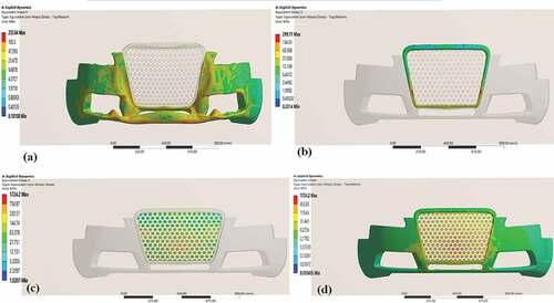
Table 3. Equivalent stress values in different bumper parts
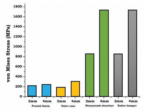
Figure 9. Comparative analysis between 2 mm thickness and 4 mm thickness bumper