
Figures & data
Figure 1. Contact between two cylindrical surfaces (Chula, Citation2017).
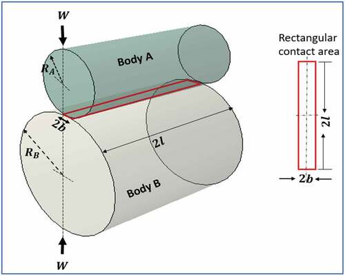
Figure 2. Schematic of the experimental setup.
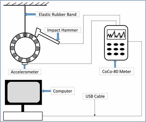
Figure 3. Experimental setup for frequency response analysis.
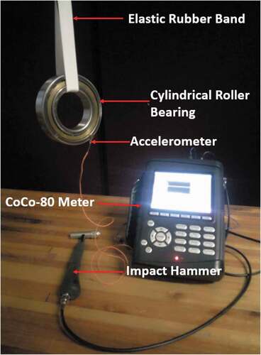
Figure 4. Experimental results postprocessing setup.
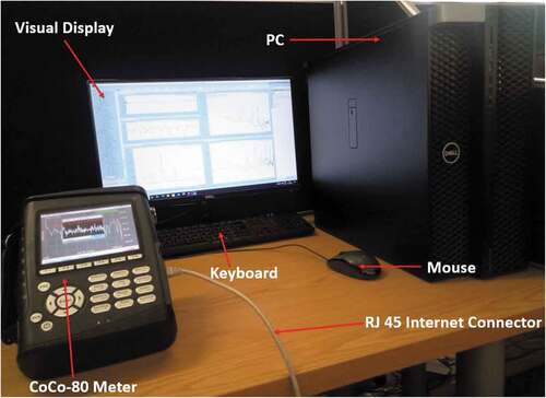
Figure 5. Parts and assembly model of cylindrical roller bearing.
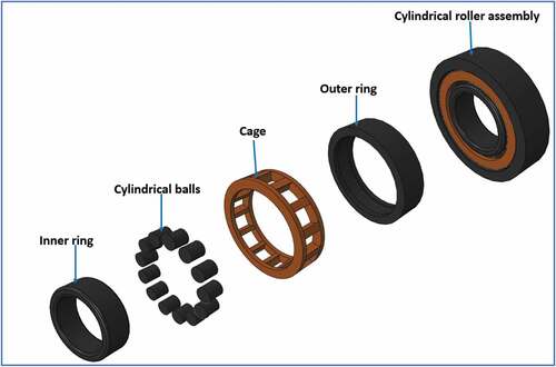
Table 1. Dimensions of cylindrical roller bearing components of an airflow root blower
Table 2. Material properties of cylindrical roller bearing components of an airflow root blower (Salifu et al., Citation2020f, Citation2020e, Citation2020a, Hlebanja et al.)
Figure 6. Applied mechanical boundary conditions of cylindrical roller bearing.
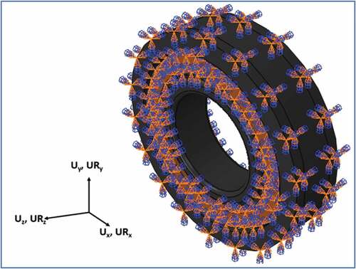
Figure 7. Mesh convergence study plot for cylindrical roller bearing.
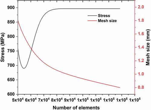
Figure 8. Parts and assembly mesh of cylindrical roller bearing.
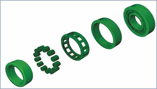
Figure 9. Mode shape for the first eight vibration modes.
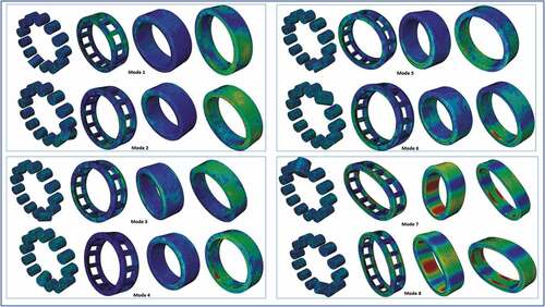
Table 3. Natural frequency and mode shapes of cylindrical bearing components
Figure 10. Comparison of the experimental and simulated frequency response plots.
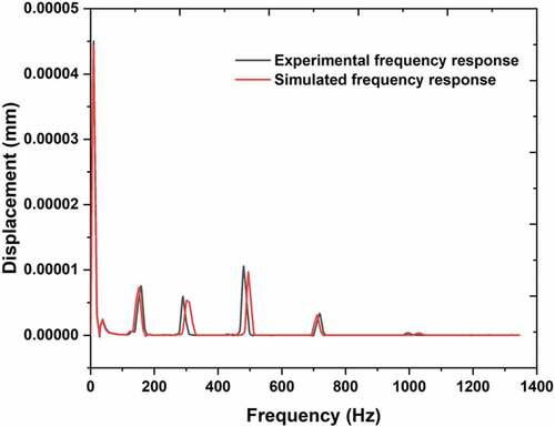
Table 4. Comparison of the first eight natural frequencies of cylindrical roller bearing
Figure 11. Temperature distribution profile contour plot and results for the different operating speeds.
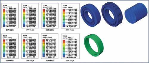
Figure 12. Results and contour plots for the distribution of heat flux for the different speeds.
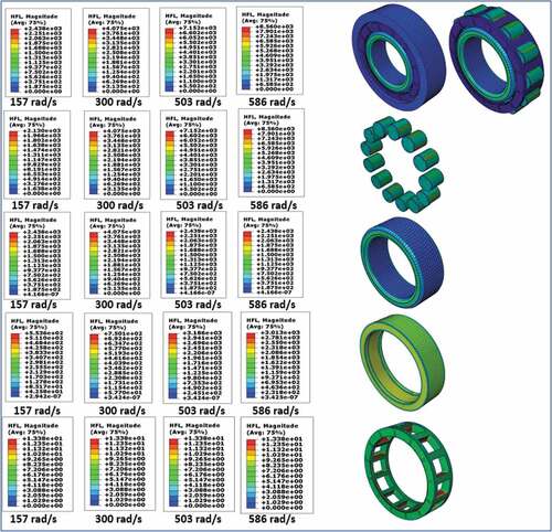
Figure 13. Contour plots and stress distribution profile results for the different operating speeds.
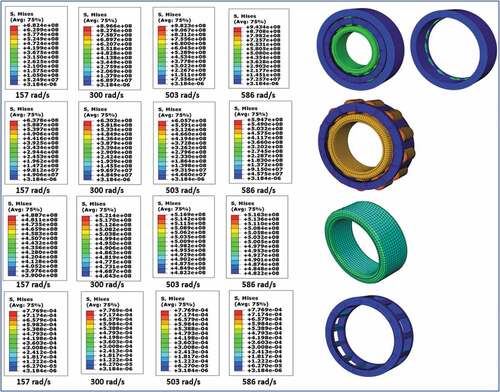
Figure 14. Fictional energy plots for the different operational speeds.
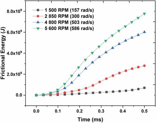
Table 5. Comparison of the FEA and analytically calculated Hertzian stress at 157 rad/s