Figures & data
Figure 1. Different passive heat transfer enhancement techniques used in circular tube heat exchanger.
Figure 2. A view of the placement of triangular wing vortex generator (TWVG) inserts inside the tube and details of various geometric parameters of TWVG.
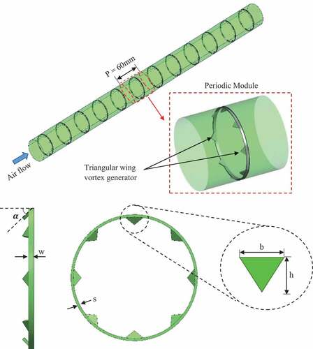
Table 1. Different configurations of triangular vortex generators
Figure 3. Details of (a) geometry of computational domain with rectangular vortex generator used in the experimental work of Zhang et al. (Zhang et al., Citation2020) having a flow attack angle (α) of 90° and (b) meshing used in the computational domain.
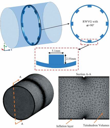
Table 2. Grid Independence test results
Figure 4. Comparison of experimental results of rectangular vortex generator (Zhang et al., Citation2020) with that of present CFD results for Nusselt number and friction factor for the flow attack angle of 90°.
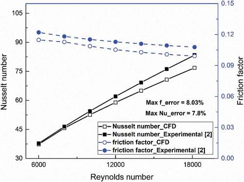
Figure 5. Variation of Nusselt number enhancement for different flow attack angle of TWVG for the geometrical configuration having h/D = 0.0784 and b/D = 0.1372.
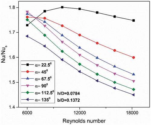
Figure 6. Comparison of flow pathlines (coloured by temperature), temperature distribution on a transverse plane at z = 32 mm from inlet, turbulence intensity (%) and Nusselt number on the tube wall for different flow attack angle of (a) 22.5° (b) 90° and (c) 135° for the TWVG configuration having h/D = 0.0784 and b/D = 0.1372.
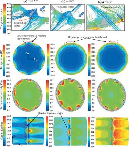
Figure 7. Comparison of temperature distribution around the TWVG in the flow direction at the central plane for different flow attack angle.
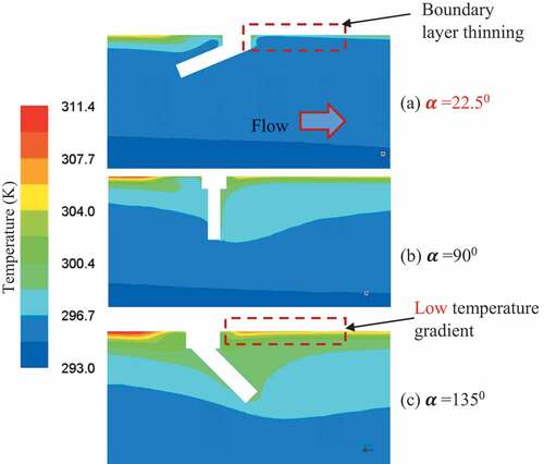
Figure 8. Comparison of friction factor enhancement for different flow attack angle of TWVG for the geometrical configuration having h/D = 0.0784 and b/D = 0.1372.
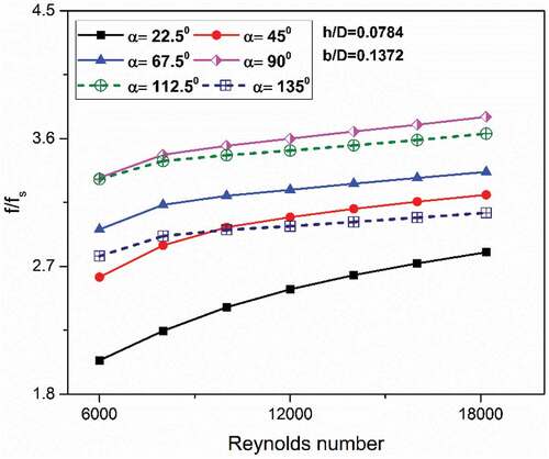
Figure 9. Variation of Nusselt number enhancement for different non-dimensional width of TWVG for the geometrical configuration having h/D = 0.3137 and α = 22.5°.
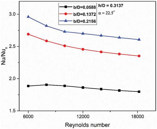
Figure 10. Comparison of flow pathlines (coloured by temperature), temperature distribution on a transverse plane at X = 32 mm from inlet, turbulence intensity (%) and Nusselt number on the tube wall for different non-dimensional width of (a) b/D = 0.0588 (b) b/D = 0.1372 and (c) b/D = 0.2156 for the TWVG configuration having h/D = 0.3137 and α = 22.5°.
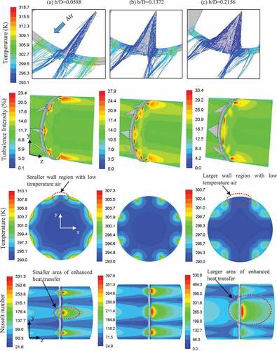
Figure 11. Variation of friction factor enhancement for different non-dimensional width of TWVG for the geometrical configuration having h/D = 0.3137 and α = 22.5°.
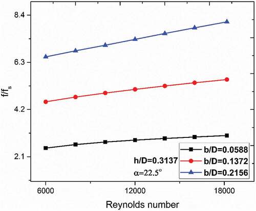
Figure 12. Comparison of pressure distribution in the air flow across the TWVG for (a) b/D = 0.0588, (b) b/D = 0.1372, (c) b/D = 0.2156 for the geometrical configuration of TWVG having h/D = 0.3137 and α = 22.5°.
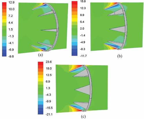
Figure 13. Variation of Nusselt number enhancement for different non-dimensional height of TWVG the geometrical configuration having b/D = 0.1372 and α = 22.5°.
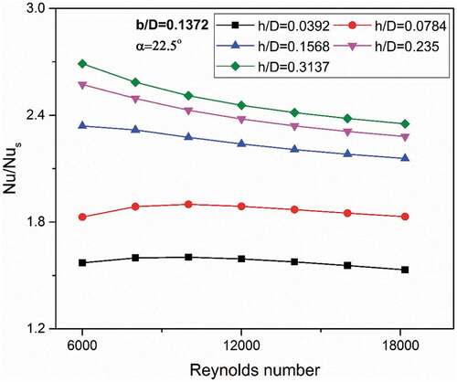
Figure 14. Comparison of flow pathlines (coloured by temperature), temperature distribution on a transverse plane at X = 32 mm from inlet, turbulence intensity (%) and Nusselt number on the tube wall for different non-dimensional width of (a) h/D = 0.0392, (b) h/D = 0.1568 and (c) h/D = 0.3137 for the TWVG configuration having b/D = 0.1372 and α = 22.5°.
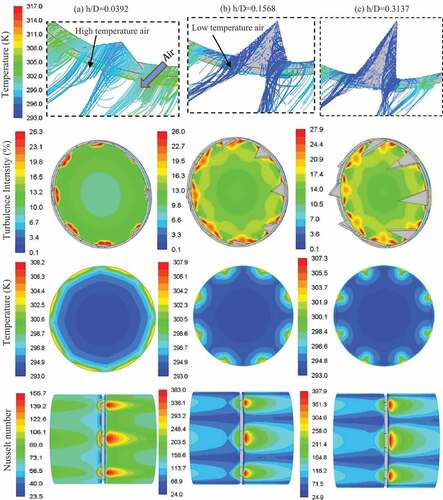
Figure 15. Variation of friction factor enhancement for different non-dimensional height of TWVG the geometrical configuration having b/D = 0.1372 and α = 22.5°.
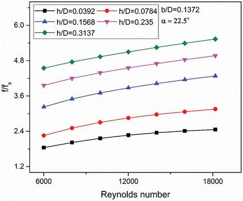
Table 3. Nusselt number enhancement for various configurations of TWVG
Table 4. Friction factor enhancement for various configurations of TWVG
Figure 16. Comparison of TEF for different flow attack angle of TWVG having b/D = 0.1372 and h/D = 0.0784.
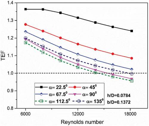
Figure 17. Comparison of TEF for different non-dimensional width of TWVG for the geometrical configuration having h/D = 0.3137 and α = 22.5°.
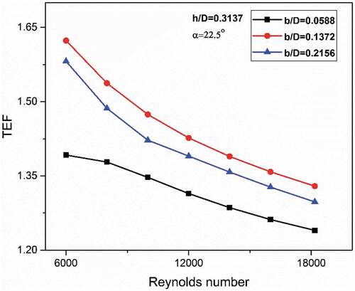
Figure 18. Comparison of TEF for different non-dimensional height of TWVG the geometrical configuration having b/D = 0.1372 and α = 22.5°.
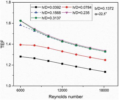
Table 5. TEF for various configurations of TWVG
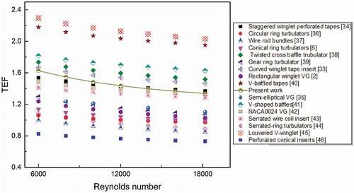
Figure 19. Comparison of TEF performance of present work with that of existing configurations of vortex generators.