Figures & data
Figure 1. FEM model calculates FS stress.
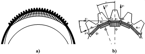
Figure 2. The change of the FS’s profile when working.
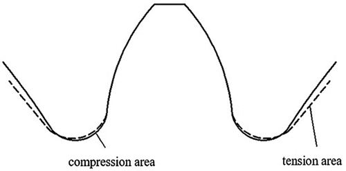
Figure 3. FS node force model.
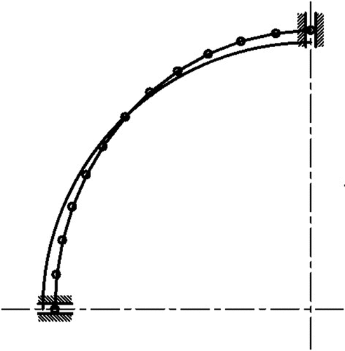
Table 1. The stiffness matrix is obtained by adding the extended matrices
Figure 4. Bar with a rotation joint and a translation joint.
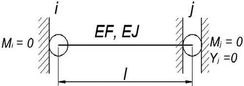
Figure 5. The process of building the displacement matrix of the element system.
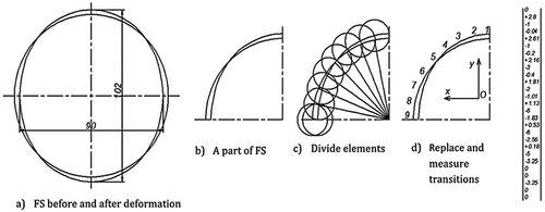
Table 2. Programmatically determine the detailed drawing of the tooth profile
Figure 6. Completed FS and CS design drawing.
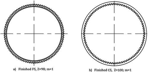
Figure 7. The design, model, and neutral curve measurement results of the FS.
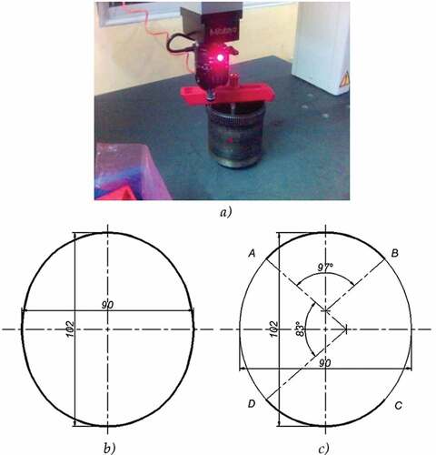
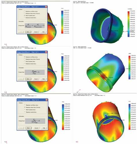
Figure 8. Computational simulation results on cosmos design star