1,757
Views
2
CrossRef citations to date
0
Altmetric
Original Articles

Field measurement and modeling of UVC cooling coil irradiation for heating, ventilating, and air conditioning energy use reduction (RP-1738)—Part 2: Energy, indoor air quality, and economic modeling

&
Pages 600-611 | Received 22 Feb 2017, Accepted 03 Aug 2017, Published online: 30 Oct 2017

Figures & data

Table 1. Baseline rates of work absence.

Table 2. Considered levels of ΔP effect due to fouling.

Table 3. Characteristics of selected DOE commercial reference buildings.

Fig. 1. Flow diagram of IAQ simulation process.

Fig. 1. Flow diagram of IAQ simulation process.

Table 4. LCCA scenarios.

Table 5. LCCA parameters.

Table 6. Parameters used in mechanical cleaning lower bound estimate.

Table 7. Summary of HVAC energy savings.

Fig. 2. Mean modeled net energy savings using ΔP lower bound and ΔP upper bound. Net includes the savings from the cooling, fan, and pump subsystems, and the energy penalty due to the heating and UVGI subsystems.
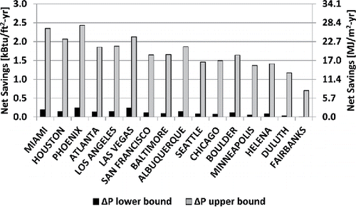
Fig. 2. Mean modeled net energy savings using ΔP lower bound and ΔP upper bound. Net includes the savings from the cooling, fan, and pump subsystems, and the energy penalty due to the heating and UVGI subsystems.

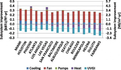
Fig. 3. Modeled mean subsystem annual energy use savings due to UVGI for ΔP lower bound. Positive values indicate energy savings and negative values indicate energy penalty.
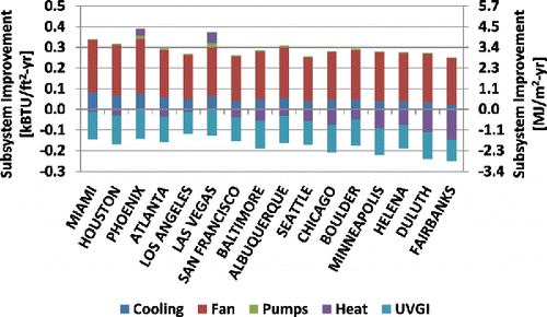
Fig. 3. Modeled mean subsystem annual energy use savings due to UVGI for ΔP lower bound. Positive values indicate energy savings and negative values indicate energy penalty.

Fig. 4. Modeled mean subsystem annual energy use savings due to UVGI for ΔP upper bound.

Fig. 4. Modeled mean subsystem annual energy use savings due to UVGI for ΔP upper bound.

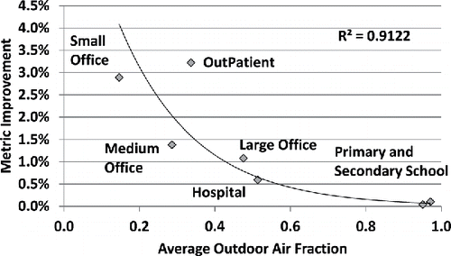
Fig. 5. Relation between OA fraction and metric improvement for Chicago climate.

Fig. 5. Relation between OA fraction and metric improvement for Chicago climate.

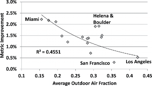
Fig. 6. Relation between OA fraction and metric improvement in medium office building.

Fig. 6. Relation between OA fraction and metric improvement in medium office building.

Table 8. Annual economic benefit per unit area by building type (all climates).

Table 9. LCC using ΔP lower bound.

Table 10. LCC using ΔP upper bound.

Fig. 7. Median LCC all options using ΔP upper bound and ΔP upper bound results. A negative cost indicates a net savings to the owner.
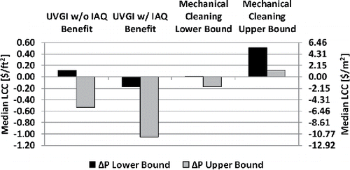
Fig. 7. Median LCC all options using ΔP upper bound and ΔP upper bound results. A negative cost indicates a net savings to the owner.

Table 11. Percentage of cases with owner net savings.

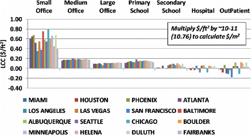
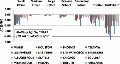
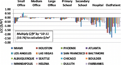
Fig. A1. LCC of ΔP lower bound using UVGI without taking into account IAQ benefit.

Fig. A1. LCC of ΔP lower bound using UVGI without taking into account IAQ benefit.

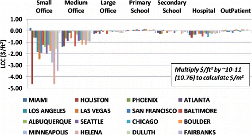
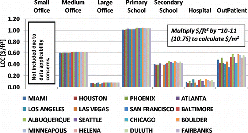
Fig. A2. LCC of ΔP upper bound using UVGI without taking into account IAQ benefit.

Fig. A2. LCC of ΔP upper bound using UVGI without taking into account IAQ benefit.

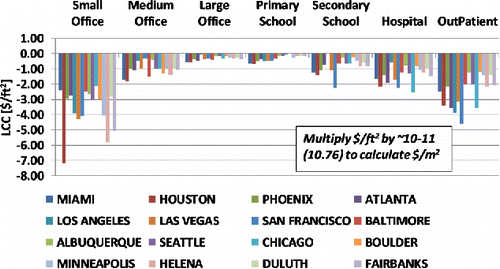
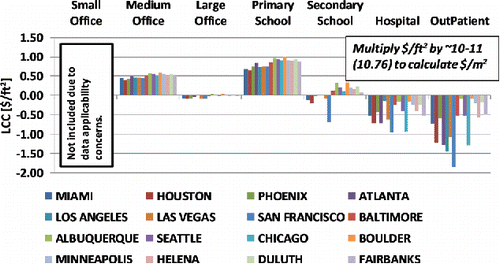
Fig. A3. LCC of ΔP lower bound using UVGI while taking into account IAQ benefit.

Fig. A3. LCC of ΔP lower bound using UVGI while taking into account IAQ benefit.

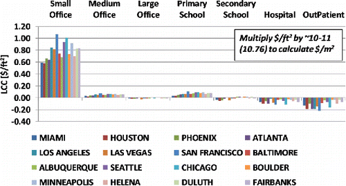
Fig. A4. LCC of ΔP upper bound using UVGI while taking into account IAQ benefit.

Fig. A4. LCC of ΔP upper bound using UVGI while taking into account IAQ benefit.

Fig. A5. LCC of ΔP lower bound using the lower bound of mechanical cleaning cost.

Fig. A5. LCC of ΔP lower bound using the lower bound of mechanical cleaning cost.

Fig. A6. LCC of ΔP upper bound using the lower bound of mechanical cleaning cost.

Fig. A6. LCC of ΔP upper bound using the lower bound of mechanical cleaning cost.

Fig. A7. LCC of ΔP lower bound using the upper bound of mechanical cleaning cost.

Fig. A7. LCC of ΔP lower bound using the upper bound of mechanical cleaning cost.

Fig. A8. LCC of ΔP upper bound using the upper bound of mechanical cleaning cost.

Fig. A8. LCC of ΔP upper bound using the upper bound of mechanical cleaning cost.