
Figures & data
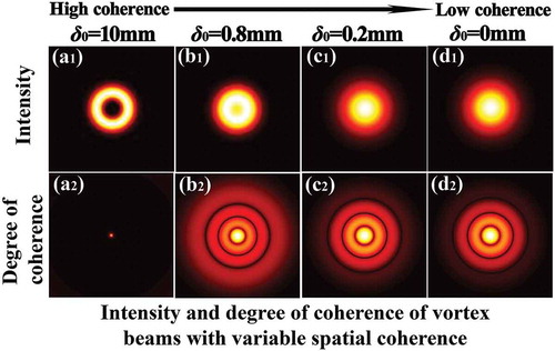
Figure 1. Focused intensity of optical coherence vortex lattices in the focal plane for different values of the initial coherence width [Citation124].
![Figure 1. Focused intensity of optical coherence vortex lattices in the focal plane for different values of the initial coherence width [Citation124].](/cms/asset/c571b16b-05f2-4ad0-ab18-fc4947d75101/tapx_a_1626766_f0001_oc.jpg)
Figure 2. Simulation of the propagation of light beam through turbulent atmosphere by multiple random phase screens [Citation144].
![Figure 2. Simulation of the propagation of light beam through turbulent atmosphere by multiple random phase screens [Citation144].](/cms/asset/44bde7ac-7d61-4fde-807d-12f714d18712/tapx_a_1626766_f0002_b.gif)
Figure 3. Focused intensity distribution of a partially coherent LG0l beam for different values of the topological charge and initial coherence width [Citation145].
![Figure 3. Focused intensity distribution of a partially coherent LG0l beam for different values of the topological charge and initial coherence width [Citation145].](/cms/asset/3c7ae094-83fb-468b-acfb-9e79a16bc4f5/tapx_a_1626766_f0003_oc.jpg)
Figure 4. Normalized intensity and modulus of the degree of coherence of a focused partially coherent LGpl beam with p= 1 and l= 1 obstructed by a sector-shaped opaque obstacle with center angle α =90° in the focal plane for different values of initial coherence width [Citation146].
![Figure 4. Normalized intensity and modulus of the degree of coherence of a focused partially coherent LGpl beam with p= 1 and l= 1 obstructed by a sector-shaped opaque obstacle with center angle α =90° in the focal plane for different values of initial coherence width [Citation146].](/cms/asset/42d123b7-7029-4359-b585-944137b539c7/tapx_a_1626766_f0004_oc.jpg)
Figure 5. Experimental setup for generating a GSM vortex beam. NDF, neutral density filter; RGGD, rotating ground-glass disk; GAF, Gaussian amplitude filter; SPP, spiral phase plate; L1, L2, thin lenses [Citation112].
![Figure 5. Experimental setup for generating a GSM vortex beam. NDF, neutral density filter; RGGD, rotating ground-glass disk; GAF, Gaussian amplitude filter; SPP, spiral phase plate; L1, L2, thin lenses [Citation112].](/cms/asset/08be101c-0daf-469a-8894-2e2301f91ac4/tapx_a_1626766_f0005_oc.jpg)
Figure 6. Experimental setup for generating nonconventional correlated partially coherent vortex beams [Citation124].
![Figure 6. Experimental setup for generating nonconventional correlated partially coherent vortex beams [Citation124].](/cms/asset/fa3cbaf0-d5e6-4f44-87c4-b7c46ae964b2/tapx_a_1626766_f0006_oc.jpg)
Figure 7. Experimental results of the normalized-focused intensity distribution of optical coherence vortex lattices for different initial coherence width [Citation124].
![Figure 7. Experimental results of the normalized-focused intensity distribution of optical coherence vortex lattices for different initial coherence width [Citation124].](/cms/asset/0633a882-e5ad-498f-b1db-977e9eded122/tapx_a_1626766_f0007_oc.jpg)
Figure 8. Experimental setup for digital generation of partially coherent vortex beams. BE, beam expander; SLM, spatial light modulator; L1, L2, thin lens; D, aperture [Citation156].
![Figure 8. Experimental setup for digital generation of partially coherent vortex beams. BE, beam expander; SLM, spatial light modulator; L1, L2, thin lens; D, aperture [Citation156].](/cms/asset/65332e51-22d3-40fd-968e-ff9f461c6140/tapx_a_1626766_f0008_oc.jpg)
Figure 9. Numerical results of the interference pattern of a GSM vortex beam for different values of the initial coherence width with topological charge l= 2.
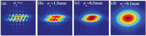
Figure 10. Distribution of the modulus of the degree of coherence of a partially coherent LG0l beam with different values of the topological charge l in the focal plane for different state of coherence [Citation145].
![Figure 10. Distribution of the modulus of the degree of coherence of a partially coherent LG0l beam with different values of the topological charge l in the focal plane for different state of coherence [Citation145].](/cms/asset/f36fb3ec-dc7e-4b52-9839-fc4621283783/tapx_a_1626766_f0010_oc.jpg)
Figure 11. (a–e) Theoretical simulations of the logarithm of the correlation function of a partially coherent LG0l beam for different topological charges at certain propagation distance after passing through a couple of perpendicular cylindrical lenses [Citation131].
![Figure 11. (a–e) Theoretical simulations of the logarithm of the correlation function of a partially coherent LG0l beam for different topological charges at certain propagation distance after passing through a couple of perpendicular cylindrical lenses [Citation131].](/cms/asset/745a0427-c17a-4ce1-8751-94659033c03c/tapx_a_1626766_f0011_oc.jpg)