
Figures & data
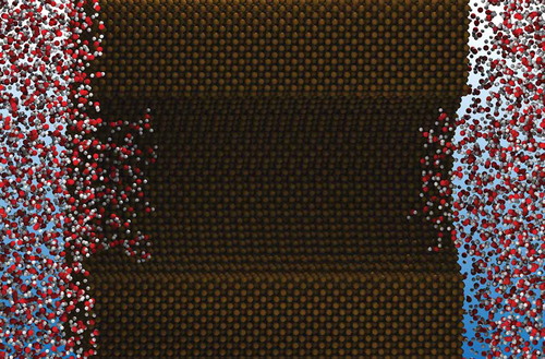
Figure 1. The probability of finding a bubble in a slightly hydrophobic gate of a biological ion channel following the geometry of KcsA [Citation66] as a function of the lower diameter
, which should be compared to the diameter of water that is set at 2.8 Å in this calculation [Citation32]. As the lower diameter
changes from narrow to wide, the probability of finding a bubble changes from roughly 1 to nearly 0. The key quantity driving this behaviour is
, given in EquationEquation (9)
(9)
(9) , the difference in the free energy of the gate blocked by a bubble and one in the same geometrical configuration filled by water. The KcsA structures are adapted from Ref [Citation83], Copyright (2008) National Academy of Sciences, U.S.A. The ion currents shown in this figure illustrate the result that can be observed in patch-clamp experiments [Citation68].
![Figure 1. The probability Pbubble(D) of finding a bubble in a slightly hydrophobic gate of a biological ion channel following the geometry of KcsA [Citation66] as a function of the lower diameter D, which should be compared to the diameter of water that is set at 2.8 Å in this calculation [Citation32]. As the lower diameter D changes from narrow to wide, the probability of finding a bubble changes from roughly 1 to nearly 0. The key quantity driving this behaviour is ΔΩ, given in EquationEquation (9)(9) ΔΩ(D)=Ωbubble(D)−Ωwater(D)=ΔPVv+ΔγAv+ΔκCv+γlv(Alv,1+Alv,2),(9) , the difference in the free energy of the gate blocked by a bubble and one in the same geometrical configuration filled by water. The KcsA structures are adapted from Ref [Citation83], Copyright (2008) National Academy of Sciences, U.S.A. The ion currents shown in this figure illustrate the result that can be observed in patch-clamp experiments [Citation68].](/cms/asset/9a17f5af-c130-49f2-b5bc-20f7c13c5752/tapx_a_1817780_f0001_oc.jpg)
Figure 2. The ensemble averaged density profile of water, modelled as a square-well fluid, in two geometrical configurations of an ion channel following the geometry of KcsA [Citation66] treated by a
DFT calculation. In the narrow gate geometry a bubble forms in the gate and blocks ions from diffusing through the channel, while a sufficiently wide gate allows water in the gate that, in turn, enables ions to follow their electro-chemical gradient. Figures are adapted from Ref [Citation82].
![Figure 2. The ensemble averaged density profile ρ(r) of water, modelled as a square-well fluid, in two geometrical configurations of an ion channel following the geometry of KcsA [Citation66] treated by a 3d DFT calculation. In the narrow gate geometry a bubble forms in the gate and blocks ions from diffusing through the channel, while a sufficiently wide gate allows water in the gate that, in turn, enables ions to follow their electro-chemical gradient. Figures are adapted from Ref [Citation82].](/cms/asset/f3fb6d71-38ae-4270-82e5-39c76fcb19be/tapx_a_1817780_f0002_oc.jpg)
Figure 3. Illustration of classical nucleation theory (CNT). a) Total free energy for homogeneous nucleation (solid blue line), given by the sum of energetically favourable bulk terms (dash-dotted line) and unfavourable surface ones (dotted line). b) Comparison of critical bubbles for heterogeneous nucleation at surfaces with simple shapes highlights the influence of surface curvature on the critical volume and, consequently, on the free-energy barriers (adapted from [Citation89], see also [Citation86]). c) Ratio of the nucleation free-energy barrier at a flat surface and the bulk barrier as a function of the contact angle of the surface.
![Figure 3. Illustration of classical nucleation theory (CNT). a) Total free energy for homogeneous nucleation (solid blue line), given by the sum of energetically favourable bulk terms (dash-dotted line) and unfavourable surface ones (dotted line). b) Comparison of critical bubbles for heterogeneous nucleation at surfaces with simple shapes highlights the influence of surface curvature on the critical volume and, consequently, on the free-energy barriers (adapted from [Citation89], see also [Citation86]). c) Ratio of the nucleation free-energy barrier at a flat surface and the bulk barrier as a function of the contact angle θY of the surface.](/cms/asset/dbd3be62-c301-4cbc-8d1e-10425963000b/tapx_a_1817780_f0003_oc.jpg)
Figure 4. Drying process in a cylindrical nanopore: a) experimental results from [Citation22]; b) bubble morphologies predicted by CNT; c) comparison of free energy from atomistic simulations (circles) and CNT (green line); d) drying/wetting cycles in cylindrical nanopores for different durations of the cycle. Panel a) is adapted from [Citation22], panels b-d) from [Citation21].
![Figure 4. Drying process in a cylindrical nanopore: a) experimental results from [Citation22]; b) bubble morphologies predicted by CNT; c) comparison of free energy from atomistic simulations (circles) and CNT (green line); d) drying/wetting cycles in cylindrical nanopores for different durations of the cycle. Panel a) is adapted from [Citation22], panels b-d) from [Citation21].](/cms/asset/71c8c297-0ac5-48a1-96c5-6bb2cba09559/tapx_a_1817780_f0004_oc.jpg)