
Figures & data
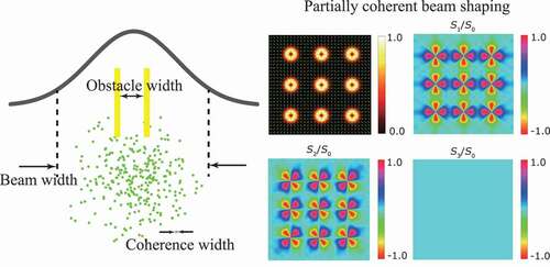
Figure 1. Spatial distributions for function (a–f) and for the corresponding spatial coherence structure (g–l) for the Gaussian-correlated, Laguerre-Gaussian-correlated, multi-Gaussian-correlated, Hermite-Gaussian-correlated, Cosine-Gaussian-correlated, and rectangular multi-Gaussian-correlated Schell-model sources. (m–o) Spatial distributions for
function and for the amplitude and phase of the spatial coherence structure for the self-steering partially coherent source. (p–r) Spatial distributions for
function and for the amplitude and phase of the spatial coherence structure for the Airy-correlated partially coherent source
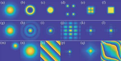
Figure 2. Partially coherent beam shaping with spatial coherence structure engineering. (a) Self-splitting and self-combining of a focused Hermite-Gaussian-correlated beam [Citation70]. (b) Self-steering of a phase-engineered partially coherent beam [Citation80]. (c) Optical cage formation with a focused Laguerre-Gaussian-correlated beam [Citation155]. (d) Evolution of the intensity and the degree of polarization for the specially correlated partially coherent vector beam during propagation [Citation97]
![Figure 2. Partially coherent beam shaping with spatial coherence structure engineering. (a) Self-splitting and self-combining of a focused Hermite-Gaussian-correlated beam [Citation70]. (b) Self-steering of a phase-engineered partially coherent beam [Citation80]. (c) Optical cage formation with a focused Laguerre-Gaussian-correlated beam [Citation155]. (d) Evolution of the intensity and the degree of polarization for the specially correlated partially coherent vector beam during propagation [Citation97]](/cms/asset/48627cba-b9cd-40a1-ac09-a28d21e4fdba/tapx_a_2009742_f0002_oc.jpg)
Figure 3. High quality beam shaping with low spatial coherence. (a) The images formed by passing the beams with different spatial coherence widths through four pinholes [Citation80]. (b) High-quality Bessel beam array generation by spatial coherence structure engineering [Citation162]. (c) High-quality radially polarized beam array generated by focusing the specially correlated partially coherent vector beam though lens array [Citation163]
![Figure 3. High quality beam shaping with low spatial coherence. (a) The images formed by passing the beams with different spatial coherence widths through four pinholes [Citation80]. (b) High-quality Bessel beam array generation by spatial coherence structure engineering [Citation162]. (c) High-quality radially polarized beam array generated by focusing the specially correlated partially coherent vector beam though lens array [Citation163]](/cms/asset/8828e64f-244c-4f15-b5ab-990e138f7156/tapx_a_2009742_f0003_oc.jpg)
Figure 4. Self-reconstruction and robustness of a partially coherent beam with engineered spatial coherence structure propagation through the complex media. (a) Physical interpretation of the self-reconstruction capacity when the relation holds, where
, and
are the widths for the spatial coherence, obstacle size, and beam intensity. (b)–(c) Intensity distribution of the specially correlated partially coherent vector beam at several propagation distances (b) without obstructed, (c) and (d) with sector-shaped opaque object of center angle
and
placed in the source plane. (e) Experimental setup for analyzing fully coherent radially polarized beam and specially correlated partially coherent vector beam transmission through a turbid medium with random refractive index fluctuations. (f) Experimental intensity profile self-reconstruction of the fully coherent radially polarized beam passing through diluted milk at different instances of time
. (g) Experimental intensity profile for the specially correlated partially coherent vector beam [Citation163]
![Figure 4. Self-reconstruction and robustness of a partially coherent beam with engineered spatial coherence structure propagation through the complex media. (a) Physical interpretation of the self-reconstruction capacity when the relation σc<σa<σI holds, where σc,σa, and σI are the widths for the spatial coherence, obstacle size, and beam intensity. (b)–(c) Intensity distribution of the specially correlated partially coherent vector beam at several propagation distances (b) without obstructed, (c) and (d) with sector-shaped opaque object of center angle φ=7π/4 and φ=71π/36 placed in the source plane. (e) Experimental setup for analyzing fully coherent radially polarized beam and specially correlated partially coherent vector beam transmission through a turbid medium with random refractive index fluctuations. (f) Experimental intensity profile self-reconstruction of the fully coherent radially polarized beam passing through diluted milk at different instances of time t. (g) Experimental intensity profile for the specially correlated partially coherent vector beam [Citation163]](/cms/asset/a5c5ae8e-f564-490f-98d6-997f09c50984/tapx_a_2009742_f0004_oc.jpg)
Figure 5. Experimental realization of the spatial coherence structure engineering by coherent-mode superposition. (a) Schematic diagram for the coherent-mode representation (CMR), pseudo-mode representation (PMR), and random-mode representation (RMR) [Citation188]. (b) Experimental setup for the spatial coherence structure engineering by coherent-mode superposition. (c) The computer generated holograms and their probability loaded on the digital micro-mirror device (DMD) [Citation184]
![Figure 5. Experimental realization of the spatial coherence structure engineering by coherent-mode superposition. (a) Schematic diagram for the coherent-mode representation (CMR), pseudo-mode representation (PMR), and random-mode representation (RMR) [Citation188]. (b) Experimental setup for the spatial coherence structure engineering by coherent-mode superposition. (c) The computer generated holograms and their probability loaded on the digital micro-mirror device (DMD) [Citation184]](/cms/asset/5946adf2-d953-4254-9f1c-6f8095cc57ba/tapx_a_2009742_f0005_oc.jpg)
Figure 6. Application in optical encryption. (a) Encoding of an optical image into the spatial coherence structure of a random light beam through a generalized van Cittert-Zernike theorem formed by a dynamic diffuser and an encoding system with the encryption keys embedded inside. (b) The experimental results for the measured spatial coherence structure and the corresponding recovered image in the turbulence free situation. (c) The experimental results in the presence of thermally induced turbulence with the temperature of hot graphitic plate being 250°C [Citation85]
![Figure 6. Application in optical encryption. (a) Encoding of an optical image into the spatial coherence structure of a random light beam through a generalized van Cittert-Zernike theorem formed by a dynamic diffuser and an encoding system with the encryption keys embedded inside. (b) The experimental results for the measured spatial coherence structure and the corresponding recovered image in the turbulence free situation. (c) The experimental results in the presence of thermally induced turbulence with the temperature T of hot graphitic plate being 250°C [Citation85]](/cms/asset/7d5583fe-f223-4338-8f4a-28ab7232d854/tapx_a_2009742_f0006_oc.jpg)
Figure 7. Application in moving targets tracking through scattering media. (a) Schematic diagram for non-line-of-sight imaging using spatial coherence. (b) Measured complex spatial coherence distribution. (c) 1D projection of the intensity of the recovered images [Citation191]
![Figure 7. Application in moving targets tracking through scattering media. (a) Schematic diagram for non-line-of-sight imaging using spatial coherence. (b) Measured complex spatial coherence distribution. (c) 1D projection of the intensity of the recovered images [Citation191]](/cms/asset/5bd72057-5459-4507-900a-83f7d3d504ac/tapx_a_2009742_f0007_oc.jpg)
Figure 8. Application in robust optical imaging. (a)Schematics of the experimental setup for a optical imaging system with its Fourier plane partially blocked by a sector-shaped opaque obstacle and the input plane is illuminated by a partially coherent light. (b) The output images by the fully coherent, partially coherent GSM, and partially coherent special correlated illuminations [Citation195]
![Figure 8. Application in robust optical imaging. (a)Schematics of the experimental setup for a 4f optical imaging system with its Fourier plane partially blocked by a sector-shaped opaque obstacle and the input plane is illuminated by a partially coherent light. (b) The output images by the fully coherent, partially coherent GSM, and partially coherent special correlated illuminations [Citation195]](/cms/asset/75ef7c28-0ea1-4ce5-99d7-cbedb76280a6/tapx_a_2009742_f0008_oc.jpg)