Figures & data
Figure 1. Bard Stinger Ablation Catheter and its control unit (a) the catheter with the control unit; (b) the distal tip of the catheter; (c) the inside of the control unit.
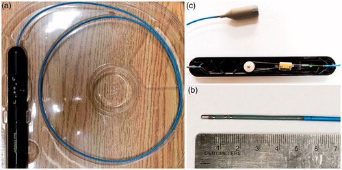
Table 1. Comparisons of some typical steerable catheters in the literature.
Figure 2. Schematic diagram of the structure of the tendon-driven steerable catheter. (The red arrows indicate the movement of tendon and the deflection of the distal section)
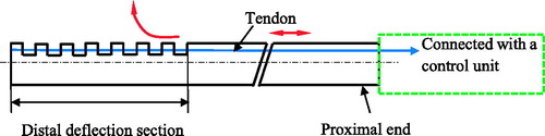
Figure 3. Location and number of tendons in the tendon-drive catheters. (a) The catheter is driven by one tendon and examples can be found in [Citation5,Citation35–37]; (b) The catheter is driven by a pair of tendons which are placed in 180° and examples can be found in [Citation15,Citation38,Citation39]; (c) The catheter is driven by three tendons placed 120° apart and examples can be found in [Citation40,Citation41]; (d) The catheter is driven by four orthogonally spaced tendons and examples can be found in [Citation16,Citation42,Citation43].
![Figure 3. Location and number of tendons in the tendon-drive catheters. (a) The catheter is driven by one tendon and examples can be found in [Citation5,Citation35–37]; (b) The catheter is driven by a pair of tendons which are placed in 180° and examples can be found in [Citation15,Citation38,Citation39]; (c) The catheter is driven by three tendons placed 120° apart and examples can be found in [Citation40,Citation41]; (d) The catheter is driven by four orthogonally spaced tendons and examples can be found in [Citation16,Citation42,Citation43].](/cms/asset/49b1bef9-4cf2-471f-95b3-a095a6f4d884/icsu_a_1526972_f0003_b.jpg)
Figure 4. Steerable catheters with an open lumen. (Left: The cannula driven by two tendons with an open lumen was designed by Kutzer et al. [Citation15]. Reprinted with the permission from [Citation15] © 2011 IEEE. Right: The catheter driven by four tendons with an open lumen was designed by Jung et al. [Citation42]. Reprinted with the permission from [Citation42] © 2011 IEEE.
![Figure 4. Steerable catheters with an open lumen. (Left: The cannula driven by two tendons with an open lumen was designed by Kutzer et al. [Citation15]. Reprinted with the permission from [Citation15] © 2011 IEEE. Right: The catheter driven by four tendons with an open lumen was designed by Jung et al. [Citation42]. Reprinted with the permission from [Citation42] © 2011 IEEE.](/cms/asset/98fd14fe-0775-4b9b-8ea0-eac5b240fd01/icsu_a_1526972_f0004_c.jpg)
Figure 5. Cross-sectional view of the tendon driven steerable catheter [Citation43].
![Figure 5. Cross-sectional view of the tendon driven steerable catheter [Citation43].](/cms/asset/081ea876-50e7-4c92-96fd-2928771e4331/icsu_a_1526972_f0005_c.jpg)
Figure 6. Steerable catheters with a discrete backbone [Citation40] (Left: entire steerable catheter system; Right: one segment of the backbone). Reprinted with the permission from [Citation30] © 2006 IEEE.
![Figure 6. Steerable catheters with a discrete backbone [Citation40] (Left: entire steerable catheter system; Right: one segment of the backbone). Reprinted with the permission from [Citation30] © 2006 IEEE.](/cms/asset/7c075b50-2ddb-407a-80c2-d19a4d6d121c/icsu_a_1526972_f0006_c.jpg)
Figure 7. Bending laser manipulator developed by Harada et al. [Citation16] (Left: prototype of the manipulator; Right: bending mechanism). Reprinted with the permission from Harada et al. [Citation16] © 2006 IEEE.
![Figure 7. Bending laser manipulator developed by Harada et al. [Citation16] (Left: prototype of the manipulator; Right: bending mechanism). Reprinted with the permission from Harada et al. [Citation16] © 2006 IEEE.](/cms/asset/7a10859b-d03e-44cd-ae5e-d27fcde4448f/icsu_a_1526972_f0007_c.jpg)
Figure 8. Schematic diagram of the structure of the multi-backbone steerable catheter.
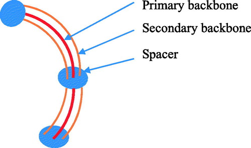
Figure 9. The section coupling (Left: co-placed; Right: distributed).
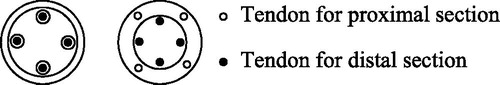
Figure 10. Niobe® ES magnetic navigation system.
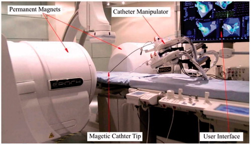
Figure 11. Overall structure of the catheter developed by Park and Esashi (Park and Esashi 1999). Reprinted with the permission from (Park and Esashi 1999) © 1999 IEEE.
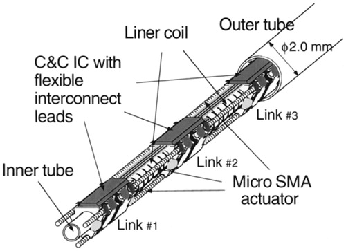
Figure 12. Laser machined SMA actuators by Tung et al. (Tung et al. 2008). Reprinted with the permission from (Tung et al. 2008) © 2008 Elsevier.
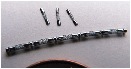
Figure 13. Movement of the needle with a bevel tip tiedles.
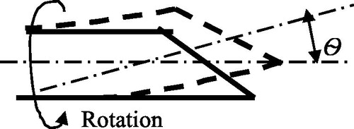
Figure 14. Active cannula made of super-elastic Nitinol tubes [Citation85]. Reprinted with the permission from [Citation85] © 2009 IEEE.
![Figure 14. Active cannula made of super-elastic Nitinol tubes [Citation85]. Reprinted with the permission from [Citation85] © 2009 IEEE.](/cms/asset/759e802a-7e62-4072-b780-169c09c15c3d/icsu_a_1526972_f0014_c.jpg)
Figure 15. Basic structure of the micro catheter [Citation11]. Reprinted with the permission, from [Citation11] © 1995 IEEE.
![Figure 15. Basic structure of the micro catheter [Citation11]. Reprinted with the permission, from [Citation11] © 1995 IEEE.](/cms/asset/05247a7b-c3b0-4570-9f30-8fc1a889e16e/icsu_a_1526972_f0015_b.jpg)
Figure 16. Structure of the catheter developed by Haga et al. (Haga et al. 2005). Reprinted with the permission from (Haga et al. 2005) © 2005 IEEE.
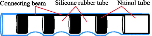
Figure 17. The prototype of two-section catheter by Bailly et al. [Citation10]. Reprinted with the permission from [Citation10] © 2005 IEEE.
![Figure 17. The prototype of two-section catheter by Bailly et al. [Citation10]. Reprinted with the permission from [Citation10] © 2005 IEEE.](/cms/asset/a26ce06f-96c0-42a4-be79-498960d27299/icsu_a_1526972_f0017_c.jpg)
Figure 18. Hydraulic pressure driven active catheter [Citation8]. Reprinted with the permission from [Citation8] © 2012 IEEE.
![Figure 18. Hydraulic pressure driven active catheter [Citation8]. Reprinted with the permission from [Citation8] © 2012 IEEE.](/cms/asset/451f321a-dcf2-44da-a89b-eecb9217cb6b/icsu_a_1526972_f0018_c.jpg)
Figure 19. Schematic diagram of robotic endoscopy developed by Butler et al. [Citation12]. Reprinted with the permission from [Citation12] © 2012 IEEE.
![Figure 19. Schematic diagram of robotic endoscopy developed by Butler et al. [Citation12]. Reprinted with the permission from [Citation12] © 2012 IEEE.](/cms/asset/fc0636a8-282a-402c-abdf-5a7051bd091c/icsu_a_1526972_f0019_b.jpg)
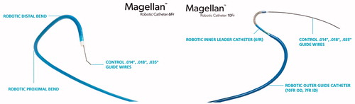
Figure 20. Magellan™ Robotic Catheter. (Left: Magellan™ 6 Fr Robotic Catheter, available at: http://www.hansenmedical.com/us/ en/ vascular/magellan-robotic-catheters/magellan-10fr-robotic-catheter; Right: Magellan™ 10 Fr Robotic Catheter, available at: http://www.hansenmedical.com/us/en/ vascular/magellan-robotic-catheters/magellan-10fr-robotic-catheter).