Figures & data
Figure 1. Typical manufacturing process flow of an additively manufactured part in a production environment.
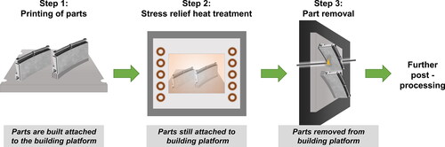
Table 1. Nominal and actual chemical compositions of Haynes® 282® superalloy powder (from powder manufacturer) and steel building platform (measured).
Figure 2. (a) Layout of various test samples on building platform in the test print; (b) stacked disc sample on steel building platform.
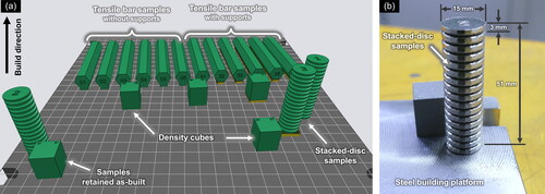
Figure 3. Schematic representation of heat treatment applied to the building platform and printed parts.
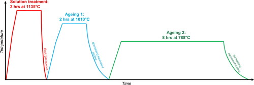
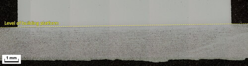
Figure 4. (a) Overview of interface between steel platform and LPBF Haynes® 282®; (b) Optical micrograph of interface region between LPBF Haynes® 282® and steel building platform before heat treatment; (c) microstructure of steel building platform before heat treatment, Nital etch.

Figure 5. EDX line scan analysis of interface region between LPBF Haynes® 282® and steel building platform in as-built condition. Red arrow indicates direction of line scan.
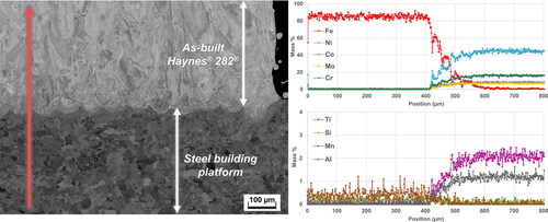
Figure 6. EDX analysis of interface region between LPBF Haynes® 282® and steel building platform in as-built condition.
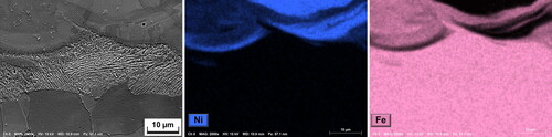
Figure 7. EDX line scan analysis of interface region between LPBF Haynes® 282® and steel building platform after heat treatment.
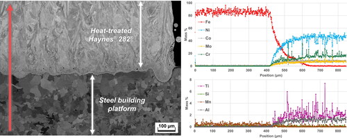
Figure 8. Microstructure of the interface region after heat treatment.
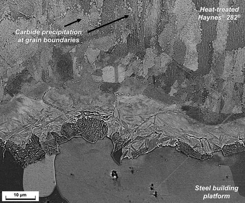
Figure 9. Microstructure and EDX analysis of interface region between Haynes® 282® and steel building platform after heat treatment.
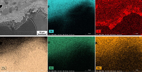
Figure 10. Hardness variation along the interface region after heat treatment.
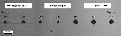
Figure 11. Chemical composition analysis results of stacked disc samples at different locations along the build height.
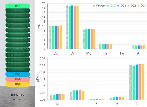
Figure 12. Mechanical properties of horizontally manufactured Haynes® 282® tensile bars at room temperature and 800 °C. “Direct” indicates that samples were heat treated with direct connection to platform. “Supports” indicates that samples were heat treated while connected to the platform by supports. “Off-platform” indicates that samples were heat treated after removal from the platform. YS = Yield stress, UTS = Ultimate tensile stress.
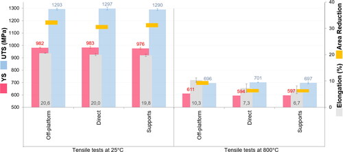
Figure 13. Macrograph showing interface region as being mainly below the level of building platform.