972
Views
31
CrossRef citations to date
0
Altmetric
Original Articles

Strategies for Enhancing Expansion in Starch-Based Microcellular Foams Produced by Supercritical Fluid Extrusion

&
Pages 23-34 | Received 08 Mar 2003, Accepted 26 Mar 2004, Published online: 06 Feb 2007

Figures & data

Table 1 Nozzle geometry, calculated pressure drop rate, experimentally determined bubble density, and expansion ratio for SCFX extrudates

Figure 1 Schematic of nozzle geometry. Three nozzle radii, R = 3.00, 2.25, and 1.50 mm, were used to vary pressure drop rates and final bubble density of the starch-based SCFX foam.
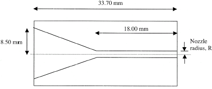
Figure 1 Schematic of nozzle geometry. Three nozzle radii, R = 3.00, 2.25, and 1.50 mm, were used to vary pressure drop rates and final bubble density of the starch-based SCFX foam.

Figure 2 Theoretical pressure profiles in extruder nozzle for three different nozzle radii, R—(i) 3.00 mm, (ii) 2.25 mm, and (iii) 1.50 mm. In the flow restrictor valve and spacer element prior to the nozzle, P drops from 10 MPa to a value determined by R. ΔPt refers to the calculated pressure drop rates in the straight section of the nozzles. The inset shows the nozzle profile with tapered (AB) and straight (BC) sections.
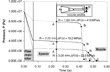
Figure 2 Theoretical pressure profiles in extruder nozzle for three different nozzle radii, R—(i) 3.00 mm, (ii) 2.25 mm, and (iii) 1.50 mm. In the flow restrictor valve and spacer element prior to the nozzle, P drops from 10 MPa to a value determined by R. ΔP/Δt refers to the calculated pressure drop rates in the straight section of the nozzles. The inset shows the nozzle profile with tapered (AB) and straight (BC) sections.

Figure 3 Average bubble diameter (D bubble) and nucleation density (N bubble) vs. nozzle radius for SCFX extrudates.
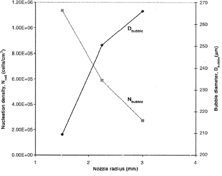
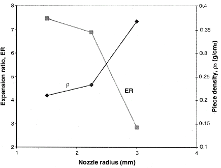
Figure 3 Average bubble diameter (D bubble) and nucleation density (N bubble) vs. nozzle radius for SCFX extrudates.
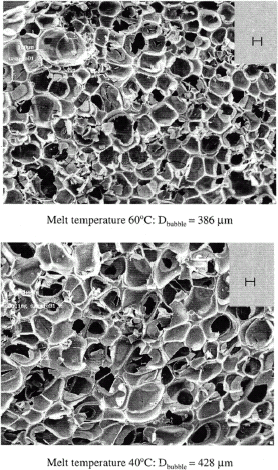
Figure 4 Expansion ratio (ER) and piece density (ρ) vs. nozzle radius for SCFX extrudates.
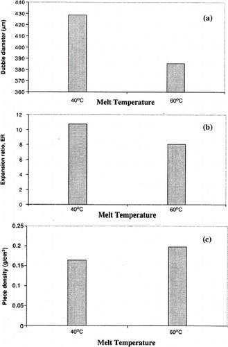
Figure 4 Expansion ratio (ER) and piece density (ρ) vs. nozzle radius for SCFX extrudates.

Figure 5 Scanning electron micrographs of SCFX extrudates showing the cellular structure obtained at two melt temperatures: (a) 60°C and (b) 40°C. Lowering the melt temperature led to an increase in average bubble diameter and greater overall expansion.

Figure 5 Scanning electron micrographs of SCFX extrudates showing the cellular structure obtained at two melt temperatures: (a) 60°C and (b) 40°C. Lowering the melt temperature led to an increase in average bubble diameter and greater overall expansion.

Figure 6 Effect of melt temperature (40 and 60°C) on (a) average bubble diameter, (b) expansion ratio, and (c) piece density of SCFX extrudates.

Figure 6 Effect of melt temperature (40 and 60°C) on (a) average bubble diameter, (b) expansion ratio, and (c) piece density of SCFX extrudates.

Reprints and Corporate Permissions

Please note: Selecting permissions does not provide access to the full text of the article, please see our help page How do I view content?

To request a reprint or corporate permissions for this article, please click on the relevant link below:

Academic Permissions

Please note: Selecting permissions does not provide access to the full text of the article, please see our help page How do I view content?

Obtain permissions instantly via Rightslink by clicking on the button below:

If you are unable to obtain permissions via Rightslink, please complete and submit this Permissions form. For more information, please visit our Permissions help page.