Figures & data
Figure 1. (a) Si/SiGe heterostructure schematic and different etching depth representation of samples studied (b) On left: representation of sample. Hall bar 4.5 mm long and Hall bar 50 μm wide. On right: representation of central part of Hall bar. Antidot lattice patterned in central part of Hall bar 230 μm long. Hexagonal symmetry of lattice is represented; side of hexagon is equal to lattice period a. Electrical measurements of antidot lattice part were made by using Hall probes 1, 2, 3, and 4. Semi-disk axis also indicated on right (for which θ = 0 degree). Electric field pointing vector of microwave for perpendicular polarization (θ = 90 degree) is represented in blue in lattice. Resulting electron flow is shown by arrows on each antidot. (c) Representation of microwave polarization orientation as function of semi disk axis. Electron flow for each polarization also indicated. Angle theta as function of antidot lattice orientation (semi disk axis) is shown.
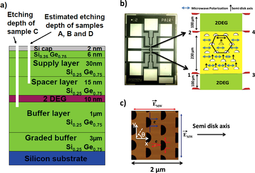
Table 1. Antidot lattice parameters and electronic properties at 4 K for samples studied. See [Citation15] for a linear antidot lattice arrangement description.
Figure 2. Normalized magnetoresistance exhibiting commensurability peaks for samples studied at 4 K. Peak of higher resistance corresponds to electron motion around one antidot. Those peaks marked by dashed line for sample D. Antidot lattice period a can be calculated from peak position in magnetic field as a = 2RC, where RC is the cyclotron radius. Commensurability peaks of lower resistance represent electron motion around 3 antidots.
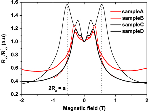
Figure 3. Ratchet photovoltage of sample C as function of magnetic field measured at 4 K. Measurements made for parallel and perpendicular microwave polarization. Microwave radiation attenuated at −10 dB.
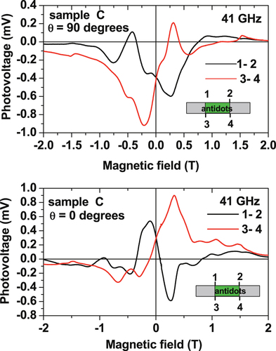
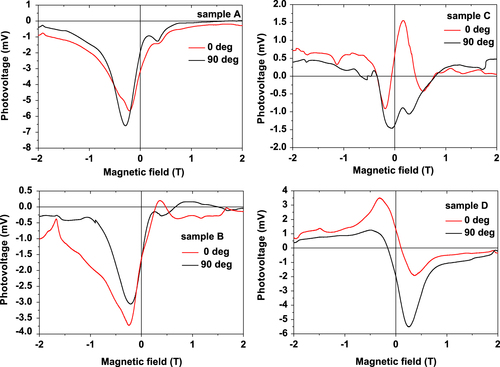
Figure 4. Ratchet photovoltage of samples A, B, C, and D as function of magnetic field measured at 4 K. Measurements made for parallel and perpendicular microwave polarization. Maximum microwave power used.