
Figures & data
Figure 1. (a) Histology of extruded Mg5-wt%Ca-1wt%Zn alloy bone screw in femoral condyle (b) magnified view of cross section of the bone screw, (c) micro-computed tomography of the bone screw at 24 weeks after operation. Reprinted by permission from Macmillan Publishers Ltd: [Citation22], copyright 2013.
![Figure 1. (a) Histology of extruded Mg5-wt%Ca-1wt%Zn alloy bone screw in femoral condyle (b) magnified view of cross section of the bone screw, (c) micro-computed tomography of the bone screw at 24 weeks after operation. Reprinted by permission from Macmillan Publishers Ltd: [Citation22], copyright 2013.](/cms/asset/d54b3fa5-689b-4d2c-9f8b-312e5126825e/tsta_a_11661325_f0001_oc.jpg)
Figure 2. Lekton Magic coronary stent (a) non-expanded (reproduced from [Citation37], copyright 2004 John Wiley and Sons), (b) expanded (reproduced from [Citation33], copyright 2006 Cambridge University Press).
![Figure 2. Lekton Magic coronary stent (a) non-expanded (reproduced from [Citation37], copyright 2004 John Wiley and Sons), (b) expanded (reproduced from [Citation33], copyright 2006 Cambridge University Press).](/cms/asset/774dbb0d-93ad-44c0-a66e-a08210a9de18/tsta_a_11661325_f0002_ob.jpg)
Figure 3. Microstructure of (a) Mg–Ca alloying (reproduced from [Citation43], under CC BY-NC 4.0 license) and (b) Mg–Zn alloying (reproduced from [Citation23], copyright 2011 Zhang B P, Wang Y, Geng L. Published in [Citation23] under CC BY 3.0 license. Available from: http://dx.doi.org/10.5772/23929).
![Figure 3. Microstructure of (a) Mg–Ca alloying (reproduced from [Citation43], under CC BY-NC 4.0 license) and (b) Mg–Zn alloying (reproduced from [Citation23], copyright 2011 Zhang B P, Wang Y, Geng L. Published in [Citation23] under CC BY 3.0 license. Available from: http://dx.doi.org/10.5772/23929).](/cms/asset/0974014f-80ff-482e-9573-5a4a0e89bd65/tsta_a_11661325_f0003_oc.jpg)
Figure 4. Mechanical properties of (a) Mg–xZn alloys (b) Mg–4.0Zn–xCa alloys (reproduced from [Citation23], copyright 2011 Zhang B P, Wang Y, Geng L. Published in [Citation23] under CC BY 3.0 license. Available from: http://dx.doi.org/10.5772/23929).
![Figure 4. Mechanical properties of (a) Mg–xZn alloys (b) Mg–4.0Zn–xCa alloys (reproduced from [Citation23], copyright 2011 Zhang B P, Wang Y, Geng L. Published in [Citation23] under CC BY 3.0 license. Available from: http://dx.doi.org/10.5772/23929).](/cms/asset/38bddb6e-e582-45bf-a56f-92705201bcb8/tsta_a_11661325_f0004_oc.jpg)
Figure 5. Classification of coatings and their corresponding processing techniques.
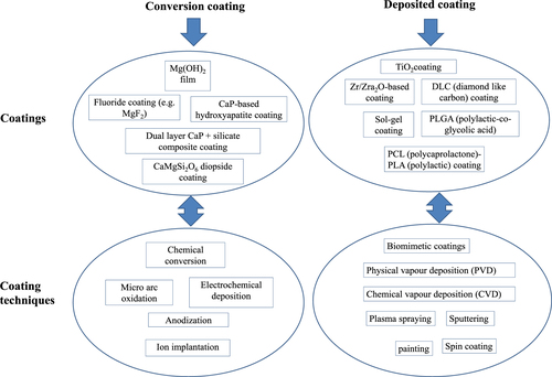
Figure 6. (a) Scanning electron microscopy (SEM) image of fluoride coated AZ31 sample (b) electrochemical impedance spectroscopy (EIS) spectra of bare and fluoride coated sample in simulated blood plasma (c) surface and cross-sectional morphologies of fluoride coated sample in simulated blood plasma at different time intervals (reprinted from [Citation51], copyright 2014, with permission from Elsevier).
![Figure 6. (a) Scanning electron microscopy (SEM) image of fluoride coated AZ31 sample (b) electrochemical impedance spectroscopy (EIS) spectra of bare and fluoride coated sample in simulated blood plasma (c) surface and cross-sectional morphologies of fluoride coated sample in simulated blood plasma at different time intervals (reprinted from [Citation51], copyright 2014, with permission from Elsevier).](/cms/asset/f89c7dd7-cdd4-4f94-b895-2689ce79fbdc/tsta_a_11661325_f0006_oc.jpg)
Figure 7. (a) SEM images of untreated and NaHCO3 treatments of Mg–Ca alloy (left) and H2 evolution of different alkaline treatments of Mg-Ca alloy (right) (reprinted from [Citation52], copyright 2009, with permission from Elsevier) (b) SEM images of cross-section of alkaline (NaOH) treated Mg–Ca1.4 alloys for different time intervals (left) and corrosion rate of bare and treated sample (right) (reprinted from [Citation54], copyright 2011, with permission from Elsevier).
![Figure 7. (a) SEM images of untreated and NaHCO3 treatments of Mg–Ca alloy (left) and H2 evolution of different alkaline treatments of Mg-Ca alloy (right) (reprinted from [Citation52], copyright 2009, with permission from Elsevier) (b) SEM images of cross-section of alkaline (NaOH) treated Mg–Ca1.4 alloys for different time intervals (left) and corrosion rate of bare and treated sample (right) (reprinted from [Citation54], copyright 2011, with permission from Elsevier).](/cms/asset/17099f7d-8374-49dd-a45b-eae4bce51710/tsta_a_11661325_f0007_oc.jpg)
Figure 8. (a) SEM image of cross-section of CaP coating on AZ31 alloy and its mass loss, i.e. corrosion rate in NaCl solution (reproduced from [Citation13], copyright 2008, with kind permission from Springer Science and Business Media). (b) SEM images of dicalcium phosphate dihydrate (DCPD), hydroxyapatite (HA) and fluoridated hydroxyapatite (FHA) coatings on Mg–Zn alloy and their corrosion performances (i.e. H2 evolutions) (reprinted from [Citation55], copyright 2010, with permission from Elsevier).
![Figure 8. (a) SEM image of cross-section of CaP coating on AZ31 alloy and its mass loss, i.e. corrosion rate in NaCl solution (reproduced from [Citation13], copyright 2008, with kind permission from Springer Science and Business Media). (b) SEM images of dicalcium phosphate dihydrate (DCPD), hydroxyapatite (HA) and fluoridated hydroxyapatite (FHA) coatings on Mg–Zn alloy and their corrosion performances (i.e. H2 evolutions) (reprinted from [Citation55], copyright 2010, with permission from Elsevier).](/cms/asset/91d0fb82-d32c-4ccd-b4fb-c12c2b9e32cf/tsta_a_11661325_f0008_oc.jpg)
Figure 9. (a) Cross-section morphology of TiO2 coated AZ31 substrate and its potentio-dynamic polarization curve with respect to the uncoated substrate (reproduced from [Citation59] under a Creative Commons Attribution License), (b) corrosion rate and cell viability of CaMgSi2O6 diopside coating along with uncoated and micro-arc oxidation (MAO) coated AZ91 substrate (reprinted from [Citation60], copyright 2014, with permission from Elsevier), (c) cross-sectional morphology and potentio-dynamic polarization curves of Zr/ZrO2 coated AZ91 substrate (reproduced from [Citation61], copyright 2011 Cambridge University Press), (d) scanning electron microscopy (SEM) images of morphologies of CaP + silicate coated AZ31 and Mg-4Y alloys immersed in polymyxin B1 (PB1), polymyxin B2 (PB2), and polymyxin B3 (PB3) after 3 days of culture (reprinted from [Citation62], copyright 2011, with permission from Elsevier).
![Figure 9. (a) Cross-section morphology of TiO2 coated AZ31 substrate and its potentio-dynamic polarization curve with respect to the uncoated substrate (reproduced from [Citation59] under a Creative Commons Attribution License), (b) corrosion rate and cell viability of CaMgSi2O6 diopside coating along with uncoated and micro-arc oxidation (MAO) coated AZ91 substrate (reprinted from [Citation60], copyright 2014, with permission from Elsevier), (c) cross-sectional morphology and potentio-dynamic polarization curves of Zr/ZrO2 coated AZ91 substrate (reproduced from [Citation61], copyright 2011 Cambridge University Press), (d) scanning electron microscopy (SEM) images of morphologies of CaP + silicate coated AZ31 and Mg-4Y alloys immersed in polymyxin B1 (PB1), polymyxin B2 (PB2), and polymyxin B3 (PB3) after 3 days of culture (reprinted from [Citation62], copyright 2011, with permission from Elsevier).](/cms/asset/e7be9271-57cb-47f4-abf1-6048cc26ced7/tsta_a_11661325_f0009_oc.jpg)
Figure 10. (a) X-ray photoelectron spectroscopy (XPS) depth profiles of oxygen-implanted AZ31 alloy, and potentiodynamic polarization curves of unimplanted and ion-implanted alloy in SBF (reprinted from [Citation84], copyright 2013, with permission from Elsevier), (b) XPS depth profiles of Ti-PIII&D implanted AZ91 alloy and Nyquist plots of as-received and PIII&D samples in SBF (reprinted from [Citation85], copyright 2007, with permission from Elsevier), (c) XPS depth profiles of WE43 alloy after Al and O plasma ion implantation, and polarization curves of unimplanted and ion-implanted alloy in SBF (reprinted from [Citation86], copyright 2012, with permission from Elsevier).
![Figure 10. (a) X-ray photoelectron spectroscopy (XPS) depth profiles of oxygen-implanted AZ31 alloy, and potentiodynamic polarization curves of unimplanted and ion-implanted alloy in SBF (reprinted from [Citation84], copyright 2013, with permission from Elsevier), (b) XPS depth profiles of Ti-PIII&D implanted AZ91 alloy and Nyquist plots of as-received and PIII&D samples in SBF (reprinted from [Citation85], copyright 2007, with permission from Elsevier), (c) XPS depth profiles of WE43 alloy after Al and O plasma ion implantation, and polarization curves of unimplanted and ion-implanted alloy in SBF (reprinted from [Citation86], copyright 2012, with permission from Elsevier).](/cms/asset/519c6f95-a67b-4ac3-a7ba-218e0ea1d239/tsta_a_11661325_f0010_oc.jpg)
Figure 11. (a) surface morphologies of CaP coating on AZ31B alloys with and without the co-presence of dentin sialophosphorprotein (3DSS) peptide (b) H2 generation and polarization profiles of non-coated and 3DSS coated AZ31B alloy (reprinted from [Citation90], copyright 2013, with permission from Elsevier).
![Figure 11. (a) surface morphologies of CaP coating on AZ31B alloys with and without the co-presence of dentin sialophosphorprotein (3DSS) peptide (b) H2 generation and polarization profiles of non-coated and 3DSS coated AZ31B alloy (reprinted from [Citation90], copyright 2013, with permission from Elsevier).](/cms/asset/52767b0c-a804-41b7-b627-af123b5c1670/tsta_a_11661325_f0011_oc.jpg)
Figure 12. Surface morphologies of short peened and dicalcium phosphate dihydrate (DCPD) coated AZ31 alloy and the corresponding impedance curves with various surface treatments (reprinted from [Citation113], copyright 2014, with permission from Elsevier), (b) residual stress on Mg–0.8Ca and Mg–3.0Ca alloys gendered by turning followed by deep rolling, their H2 generation rate and the corresponding mass loss at different time intervals (reproduced from [Citation115], copyright 2011 Leibniz Universität Hannover, IFW. Published in [Citation115] under CC BY-NC-SA 3.0 license. Available from: http://dx.doi.org/10.5772/22793), (c) cross sectional surface morphology of cryogenic + severe plasticity burnished AZ31 alloy after immersion for 200 h and its corresponding corrosion resistance (i.e. H2 generation) (reprinted from [Citation116], copyright 2011, with permission from Elsevier).
![Figure 12. Surface morphologies of short peened and dicalcium phosphate dihydrate (DCPD) coated AZ31 alloy and the corresponding impedance curves with various surface treatments (reprinted from [Citation113], copyright 2014, with permission from Elsevier), (b) residual stress on Mg–0.8Ca and Mg–3.0Ca alloys gendered by turning followed by deep rolling, their H2 generation rate and the corresponding mass loss at different time intervals (reproduced from [Citation115], copyright 2011 Leibniz Universität Hannover, IFW. Published in [Citation115] under CC BY-NC-SA 3.0 license. Available from: http://dx.doi.org/10.5772/22793), (c) cross sectional surface morphology of cryogenic + severe plasticity burnished AZ31 alloy after immersion for 200 h and its corresponding corrosion resistance (i.e. H2 generation) (reprinted from [Citation116], copyright 2011, with permission from Elsevier).](/cms/asset/162f730e-6bae-45f0-a7e8-34b6ed2bc51b/tsta_a_11661325_f0012_oc.jpg)