
Figures & data
Table 1 Properties of Cohesive Polydensified Matrix/Hyaluronic Acid Formulations. The Balance of Rheologic Properties in the CPM-HA Range is Indicated by: - Absent, + Low, ++ Medium, +++ High, ++++ Very High
Table 2 Recommendations for Forehead Augmentation and Rejuvenation
Figure 1 Forehead entry points and treatment zone. Black lines: limits of the forehead area (temporal crest, hairline, supraorbital rim) and limits of the arterial danger zone (1.5–2.0 cm superior to the supraorbital rim). Black dots: entry points. Lines from black dots: retrograde linear threads of 0.025–0.04 mL CPM-HA I or CPM-HA V with a 22G cannula, bevel directed towards the periosteum. Dotted black lines: optional additional retrograde linear threads. Image courtesy from Merz Pharmaceutical GmbH.
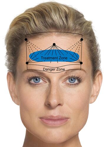
Table 3 Recommendations for Temple Contouring
Figure 2 Treatment of the temples. The posterior temple is divided into three zones (1–3), and injections in these different zones will result in different aesthetic effects. Injection in the anterior temple (zone 4) is only required for very skeletonized faces.Citation14 Zone 5 covers the same area as zone 4, but signifies smoothing of transitions in the area. Image courtesy from Merz Pharmaceutical GmbH.
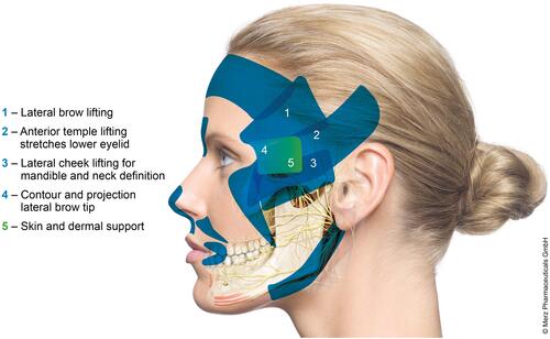
Figure 3 Before and after 1 mL CPM-HA V to the temples (other indications were treated too). Courtesy Jani van Loghem, MD.
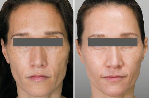
Table 4 Recommendations for Superior Orbital Hollowness
Figure 4 Periorbital landmarks.
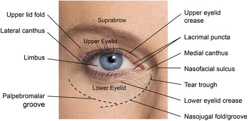
Table 5 Recommendations for Infraorbital Hollows
Figure 5 Treatment of the infraorbital hollows. Image courtesy from Merz Pharmaceutical GmbH.
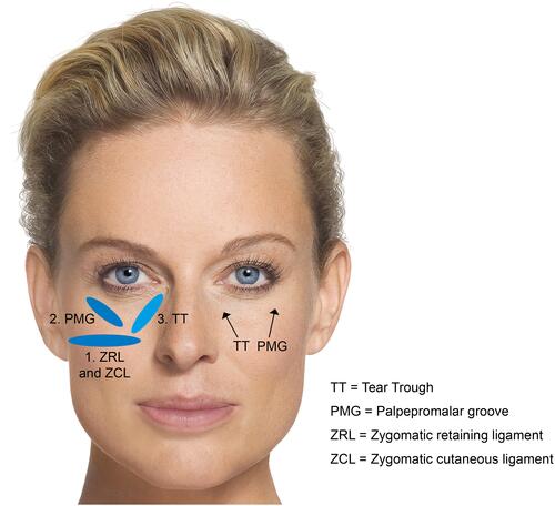
Figure 6 Clinical photo series of three stages of IOH treatment. Courtesy Jani van Loghem, MD. (A) Lateral Cheek (CPM-HA V); (B) Medial Cheek (CPM-HA V); (C) Palpebromalar groove (CPM-HA I); (D) Tear trough (CPM-HA B); (E) Result immediately after left side treated. Note the canthal tilt improvement.
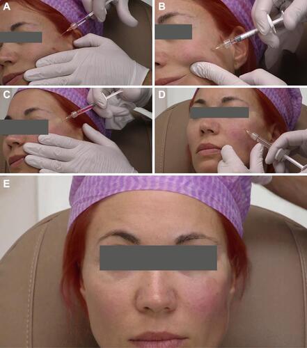
Figure 7 Pre-auricular hollowing: landmark deficiencies illustrating midface borders. The mid cheek ideally has a small concavity, resulting in a low light “shadow” from the zygoma above. In women, this concavity classically has an ovoid shape. In men, the shape tends to be more square or rectangular. Image courtesy from Merz Pharmaceutical GmbH.
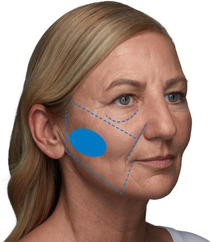
Table 6 Recommendations for Pre-Auricular Hollowing
Figure 8 Addressing mid-face hollowing. Courtesy of W. Philip Werschler, MD.
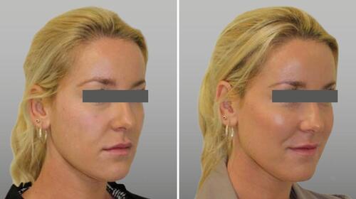
Figure 9 Types of radial cheek lines. (A) Type 1 lines: structural deficiencies. (B) Type 2 lines: skin laxity. (C) Type 3 lines: structural deficiency plus skin laxity. Courtesy of Carla Pecora, MD.
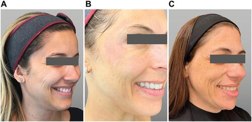
Figure 10 Image shows the left side of a male body donor after the superficial fat compartments have been injected as described previously.Citation24 Note the clear boundaries between the respective fat pads when filled with coloured fluid. Courtesy of Sebastian Cotofana.
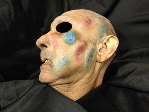
Table 7 Recommendations for Radial Cheek Lines
Figure 11 A 32-year old patient with radial cheek lines caused by lack of bone support but no photodamage (type 1 lines). In a single session, treatment with two small boluses (0.2 mL) of CPM-HA I supraperiosteal on the cheekbone and 1 mL of CPM-HA V injected subcutaneously with a fanning technique will improve the situation. Courtesy of Carla Pecora, MD.
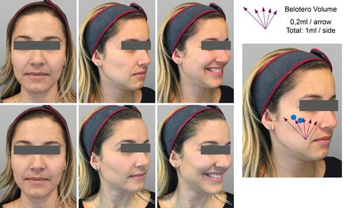
Table 8 Recommendations for Marionette Lines and Sunken Corners of the Mouth
Figure 12 Marionette lines – injection technique. Arrows represent linear retrograde strands of dermal filler and circles represent boluses. Courtesy of Sabrina Fabi, MD.
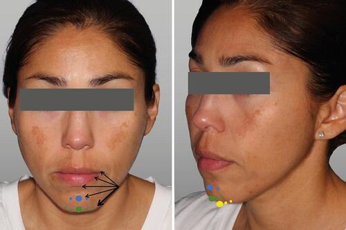
Table 9 Recommendations for Chin Augmentation
Figure 13 Injection points for chin elongation and chin projection.
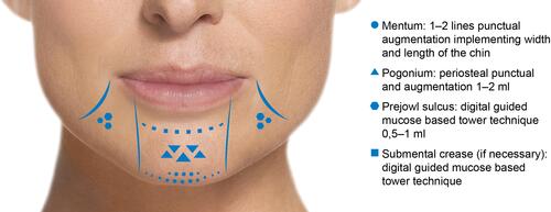
Figure 14 Before and after photos of a patient treated for chin elongation. Courtesy of Sonja Sattler, MD.
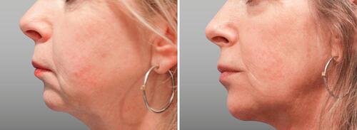
Figure 15 Before and after photos of a patient treated for chin projection. Courtesy of Sonja Sattler, MD.
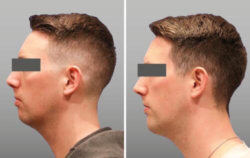
Table 10 Recommendations for the Jawline
Figure 16 Injection points for jawline rejuvenation with non-traumatic cannula. (A) Mandibular angle entry point; (B) Pre-jowl sulcus entry point. Schematics © Dr. Jani van Loghem.
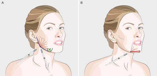
Figure 17 Before and after photos of a patient treated for jawline rejuvenation. Courtesy Jani van Loghem, MD. Patient was also treated in other facial indications.
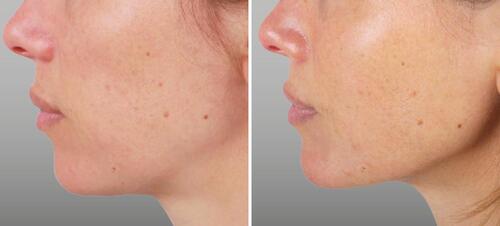
Table 11 Recommendations for the Lips
Figure 18 Before (A) and after (B) photos of lip contouring. Patient also received lip volumizing. Courtesy Dr. Jani van Loghem.
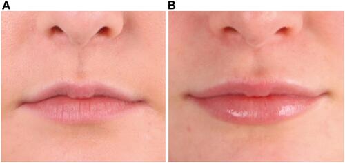
Table 12 Recommendations for Skin Revitalization