Figures & data
Table 1 Primer Sequences of the Selected Genes
Figure 1 XRD results of mnHAp (S3) and Srx-mnHAp bioceramics (2.5Sr, 5Sr, 10Sr, 20Sr).
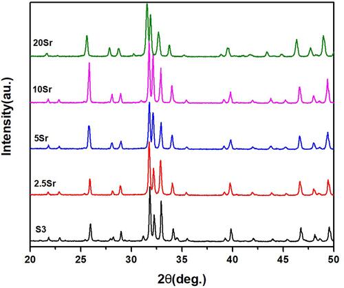
Figure 2 SEM micrographs of topographic surface for HAp (A), mnHAp (B), and Srx-mnHAp (C–F): (A) scale bar=500 nm, (B-F) scale bar=20 μm.
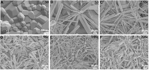
Figure 3 The release of Ca (A), P (B), and Sr (C) ions at 1 and 4 d.
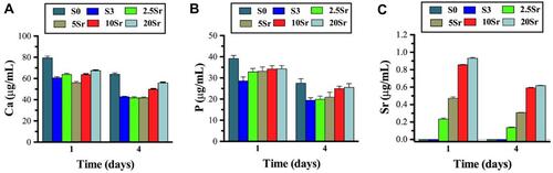
Figure 4 Fluorescence microscopy images of the cells in samples S0, S3, 2.5Sr, 5Sr, 10Sr, and 20Sr after 6 h: red represents the actin cytoskeleton (A1–F1), blue represents the nucleus (A2–F2), and the merged images of the actin cytoskeleton and the nucleus (A3–F3): scale bar=50 μm.
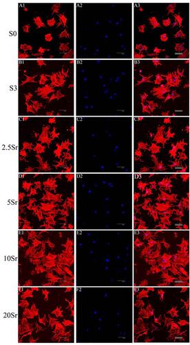
Figure 5 MTT analysis of the cells seeded in samples S0, S3, 2.5Sr, 5Sr, 10Sr and 20Sr. (* indicates a significant difference with S0, Δ indicates a significant difference with S3, p<0.05).
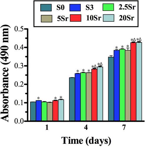
Figure 6 ALP activity measurement: (A) ALP staining of BMSCs seeded onto samples S0, S3, 2.5Sr, 5Sr, 10Sr, and 20Sr at 10 d. (B) ALP quantitative analysis of cells seeded in samples S0, S3, 2.5Sr, 5Sr, 10Sr and 20Sr for 4, 7 and 10 d. (*indicates a significant difference with S0, Δ indicates a significant difference with S3, p<0.05).
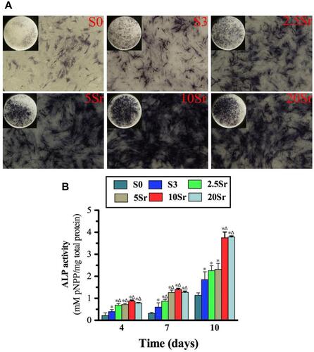
Figure 7 qRT–PCR analysis of the expression of COL1 (A), BMP-2 (B), BSP (C), OPN (D), VEGF (E), and ANG-1 (F) and Western blot result of BMP-2 (G). (*indicates a significant difference with S0, Δ indicates a significant difference with S3, p<0.05).
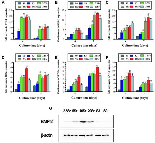
Figure 8 Micro-CT assessment at 8 weeks after implantation. (A) 3D and 2D images of newly formed bone of groups S0, S3, and 10Sr. Quantitative measurement of the BV/TV ratio (B) and Tb. Th (C). (*indicates a significant difference with S0, Δ indicates a significant difference with S3, p<0.05).
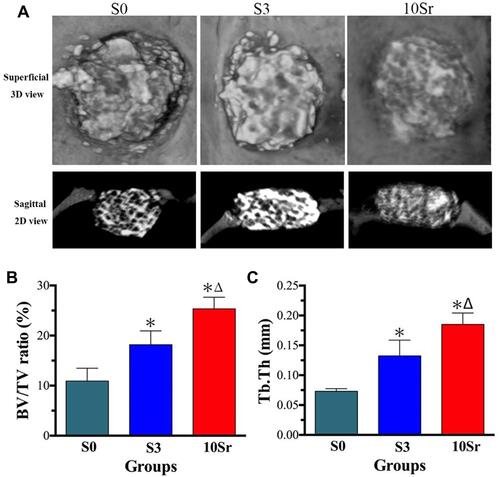
Figure 9 Micro-CT angiography at the 8th week after implantation. (A) Images of new blood vessels in groups S0, S3, and 10Sr. (B) Quantitative measurement of the new blood vessel area. (*indicates a significant difference with S0, Δ indicates a significant difference with S3, p<0.05).
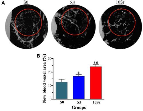
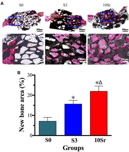
Figure 10 Histological and histomorphometric analysis: (A) Images of Van Gieson’s staining of bone formation at the 8th week after implantation. (B) Quantitative measurement of the new bone area. (*indicates a significant difference with S0, Δ indicates a significant difference with S3, p<0.05).