Figures & data
Figure 1 Two-dimensional view of the midsagittal plane of the pelvic floor.
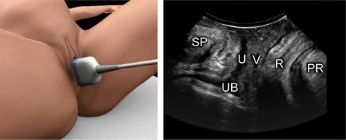
Figure 2 A comparison of the images of the axial view using the three methods for the demonstration of levator ani muscle.
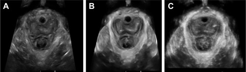
Figure 3 Tomographic ultrasound imaging of the levator ani muscle obtained by three-dimensional/four-dimensional transperineal ultrasound.
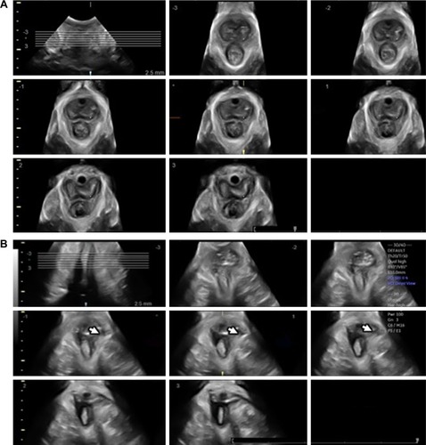
Figure 4 Measurement of the levator–urethra gap (LUG) on tomographic ultrasound imaging (TUI).
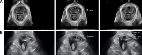
Figure 5 Three-dimensional transperineal tomographic ultrasound images of anal sphincter.
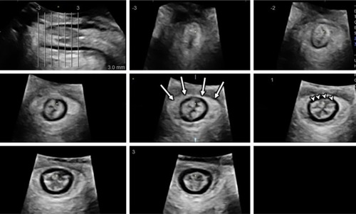
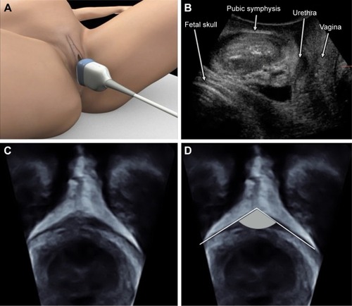
Figure 6 Technique for transperineal ultrasound scan for fetal head descent assessment on the midsagittal plane.
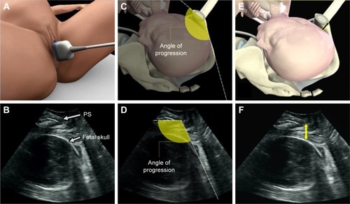
Figure 7 Technique for transperineal ultrasound scan for fetal head descent and rotation assessment on the axial plane.
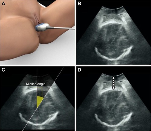
Figure 8 A multiplanar view of three-dimensional transperineal volume performed in labor.
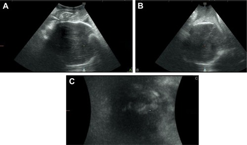
Figure 9 The subpubic arch angle (SPA).