Figures & data
Table 1 The Fusion Grade of Brantigan and Steffee Criteria
Figure 1 The schematic diagram of the procedure. (A) Placing work cannula targeting to the junction of spinous space and lamina; (B) Removing the inferior articular process; (C) Exposing and decompressing the nerve root; (D) Implanting allograft bone and PEEK cage.
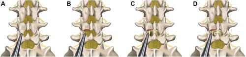
Figure 2 Intraoperative endoscopic images. (A) Confirming and marking skin entry points by C-arm; (B) Placing work cannula targeting to the junction of spinous space and lamina under C- arm fluoroscopic control; (C) Removing the inferior articular process, partial lamina, and the partial superior articular process by endoscopic drill under the full visualization; (D) Exposing nerve root after removing ligamentum flavum and hypertrophied tissues; (E) Scrapping away adequately cartilaginous endplate; (F) Checking cage position by full endoscopic visualization.
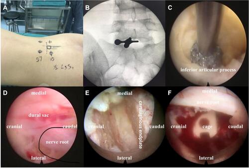
Figure 3 Intraoperative C-arm fluoroscopic control. (A–C) Installing expandable tubular, dilating intervertebral space and implanting allograft bone and PEEK cage under the C-arm fluoroscopic control; (D) Lateral X-rays showing satisfactory cage position; (E and F) Anteroposterior and lateral X-rays showing correct implant position.
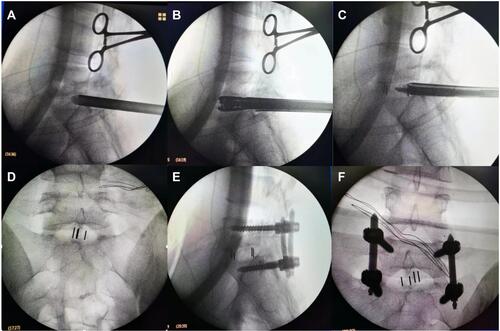
Figure 4 Instruments of ZELIF. (A and B) Guide wire, dilator, working tube and baffle of ZELIF® system; (C) Reamers and scrapers.
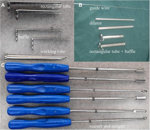
Table 2 Baseline Clinical and Perioperative Characteristics of Patients
Table 3 Preoperative and Follow-Up Functional Scores
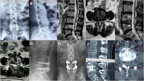
Figure 5 Images were obtained from a 48-year-old male patient with the degenerative spondylolisthesis at L5-S1. (A and B) Sagittal and axial CT images showing degenerative spondylolisthesis at L5-S1; (C and D) Postoperative anteroposterior and lateral X-rays images showing correct cage and pedicle screws after full Endo-PLIF; (E–H) Postoperative sagittal CT images at 3, 6, 9, 12 months showing interbody fusion.
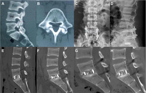
Figure 6 Images were obtained from a 51-year-old female patient with the lumbar spinal stenosis at L4-5. (A–D) Preoperative X-rays and MRI images showing lumbar spinal stenosis at L4-5; (E and F) Postoperative sagittal and axial MRI images showing complete decompression after full Endo-PLIF; (G and H) Postoperative anteroposterior and lateral X-rays at 3 months showing correct position; (I and J) Postoperative sagittal and axial CT images at 6 months showing interbody fusion.