
Figures & data

Figure 1 (A) shows the spectrum of Extended Reality (XR) that consists of Virtual Reality (VR), Augmented Reality (AR), and Mixed Reality (MR). (B) In AR and MR, Computer-generated virtual contents are projected to the users’ retina via a transparent screen with a half-silvered mirror enabling a free, unhindered view of the real scene. Therefore, users can concurrently view the real objects and the virtual information overlaid in the immediate physical environment. However, MR allows users to interact with virtual content by hand gestures (*) but not in AR. In VR, virtual contents are projected to the users’ retina via an opaque screen, and a hand-held controller (**) is used to interact with virtual contents. Therefore, users are completely immersed in the virtual environment.
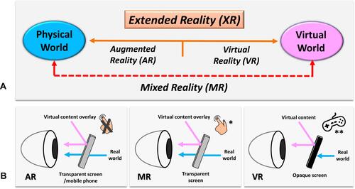
Figure 2 (A) shows the MR headset with a transparent near-eye-display, HoloLens 2 (Microsoft Corporation, Redmond, WA, USA). The Head-Mounted Display (HMD) has eye-tracking and hand tracking technology, with two cameras (white arrow) per eye. Eye-tracking is a technology that tracks the area the user is focusing on. The gaze can work as an input device like the mouse in a computer. Therefore, the technology allows interaction with holograms via gaze and hand gestures, and the user’s hands can still focus on the task. The HMD also includes an RGB camera (white arrowhead) for user-facing photo capabilities, like taking pictures and video, and live-streaming video of users’ point of view for remote assistance. (B) The author wears HoloLens 2 during the preoperative clinical assessment of a patient with the right calcaneal chondrosarcoma. The holographic contents are overlaid at the surgeon’s immediate real environment and are visualized from the surgeon’s point of view (red arrow). (C) depicts the User Interface of the authors’ developed MR platform. The MR HMD provides real-time, on-demand holographic medical information (CT/ MRI medical images in DICOM/PDF format or 3D bone model) at the clinical point of care while the surgeon can examine the patients with their hands. The system avoids the need for attention shift and eliminates line-of-site disruption, as in computer navigation surgery.
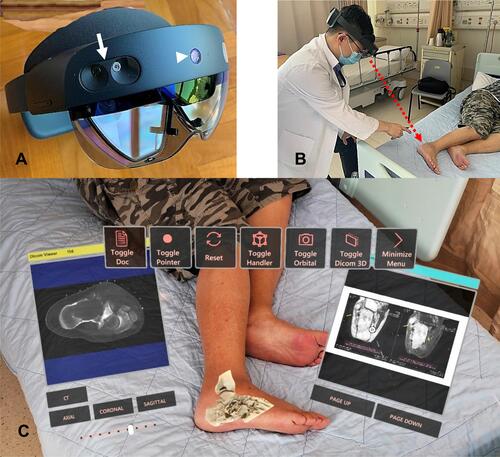
Figure 3 (A) shows the 3D-printed physical model (red arrow) and holographic virtual model in a patient with a pelvic giant cell tumor of bone. When viewing holograms, surgeons use hand gestures or voice commands to call up information instead of touching a keyboard or mouse to keep their hands free for the clinical tasks. Although the 3D-printed physical model gives tactile feedback, the surgeon needs to hold it by hand and without image feedback. Users can also analyze different sections of holographic bone models by enlarging, moving, and rotating the holographic contents by hand gestures. (B) shows the coronal view of the holographic CT bone model in a patient with a giant cell tumor involving the left femoral head and neck. The surgeon can view the different slices of the virtual model’s coronal, sagittal, and axial views by controlling the virtual buttons (red arrows). Video S1.
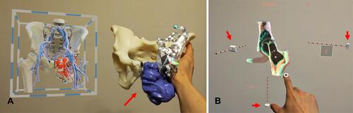
Figure 4 Depicts the conceptual design of the proposed function of remote assistance (red arrow) in the User Interface of the authors’ developed MR platform for a patient with left scapular osteosarcoma undergoing tumor resection with the assistance of a 3D-printed cutting guide. The remote surgeon/expert can view the same holographic contents and indirectly the operative field via the RGB camera of the surgeon’s MR Head-Mounted Display (HMD). The remote surgeon can text, annotate the operative photos, or bring critical medical information. Therefore, the function facilitates instant, intuitive visual and audio communication for timely operative decisions or support in contrast to traditional communication.
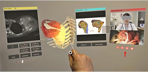
Figure 5 Summarizes the proposed clinical workflow of creating mixed reality applications from medical image acquisition to holographic applications in Orthopaedic Oncology.
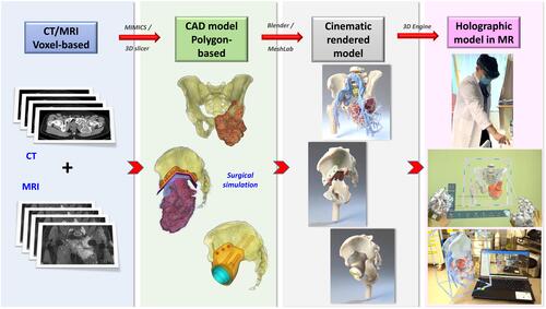
Table 1 Compares the Commercially Available Mixed Reality Head-Mounted Displays for Surgical Applications
Figure 6 Shows the Computer-Aided Design (CAD) models (A and B) and the Cinematic-Rendered (CR) models (C and D) of a man with the left pelvic giant cell tumor and a lady with the left scapular osteosarcoma, respectively. Computer graphics software generates the CR models according to data dictating the image’s color, material, and texture. It also determines the appropriate light source to simulate the natural way that light works on the polygon-based CAD models. As a result, the CR models give a more photorealistic representation of the 3D CAD models and better identify the pathological anatomy of bone tumors. Before creating the holographic application in the 3D engine, the CR models need optimization by software, like reducing polygon face number and refining the polygons’ quality for better visualization performance in the MR Head-Mounted Display (HMD) with low-end computing processing power. Video S2.
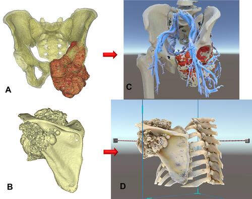
Table 2 Summarizes Studies Reporting Augmented Reality (AR)- or Mixed Reality (MR)-Guided Orthopaedic Surgery Using Head-Mounted Displays (HMDs)
Figure 7 Shows that the MR technology provides instant and on-demand critical medical information at the clinical point of care inside or outside the operating rooms for surgical planning and intraoperative reference. (A) Implant information like screw dimensions for implant fixation in a patient with a pelvic giant cell tumor undergoing tumor resection and 3D-printed custom pelvic prosthetic reconstruction. (B) The representative MRI images in a patient with a solitary T2 bone metastasis undergoing combined anterior and posterior spinal tumor resection and instrumented fixation. (C) The surgical resection planning in PDF file format in a patient with a low-grade bone sarcoma of the left tibia undergoing intercalary tumor resection under the assistance of a 3D-printed resection guide and reconstruction with a vascularized fibular graft transfer.
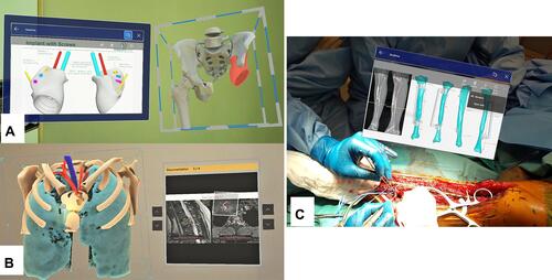
Figure 8 (A) The holographic bone model was overlaid on the left hip region in a patient with a femoral head and neck giant cell tumor of bone. Surgeons could directly “see-through” the internal patient’s anatomy, facilitating the precise skin marking for the surgical access (yellow arrows). It did not involve invasive placement of a patient’s bone tracker. (B) shows the intraoperative picture of a patient with the right calcaneal chondrosarcoma. After surgical exposure of the calcaneal tumor, the surgeon overlaid the holographic bone model onto the patient’s actual calcaneus. Together with the reference of the tumor information on the holographic MRI images, the surgeon marked the osteotomy line (yellow arrow) and did the guided-osteotomy to preserve bone insertion of the Achilles tendon for better functional reconstruction.
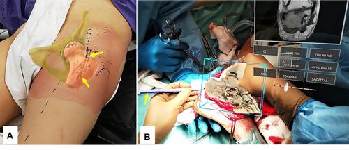
Table 3 Compares the Mixed Reality Technology with Existing Computer Navigation and 3D Printing in Orthopaedic Oncology