Figures & data
Table 1. Overview of several common 3D printing methods.
Table 2. An affordable desktop printer Form 2 (Formlabs) was used for our project. More expensive printers with larger build volumes, better resolution and/or greater material flexibility might be found in a large hospital 3D lab.
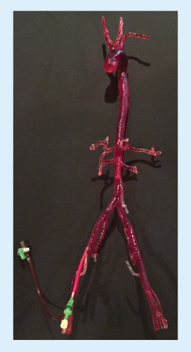
Color-coded segments (bottom right) were virtually cut to fit our printer's build volume.
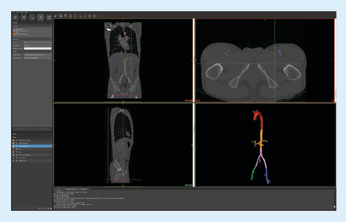
STL files manipulated using Form 2's CAD software for placement within the printer 3D build volume. Two separate prints of 8–12 h each were required to print all model parts.
CAD: Computer-aided design; STL: Standard Tessellation Language.
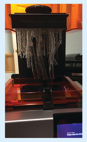
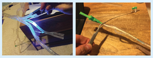
Parts were washed in isopropyl alcohol solution to remove uncured resin from the model surface. The components were fused by painting liquid resin onto the joints, and curing with a handheld UV laser (A). The model was filled with water and vascular access sheaths were secured (B).
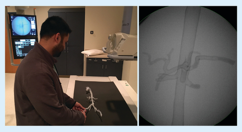
A resident practicing catheter skills (A), with corresponding fluoroscopic image of the training model (B).