588
Views
8
CrossRef citations to date
0
Altmetric
Report

Biomimetic evaluation of β tricalcium phosphate prepared by hot isostatic pressing

, , , &
Pages 103-113 | Published online: 01 Jul 2012

Figures & data

Figure 1. (A) XRD patterns of β-TCP powder (▼); (B) IR spectra of β-TCP powder.

Figure 1. (A) XRD patterns of β-TCP powder (▼); (B) IR spectra of β-TCP powder.

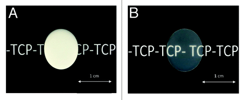
Figure 2. Photographs illustrating the transparency of TCP-T samples (B) compared with TCP (A).

Figure 2. Photographs illustrating the transparency of TCP-T samples (B) compared with TCP (A).

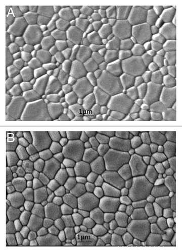
Figure 3. Initial SEM micrographs of TCP (A) and TCP-T (B) samples.

Figure 3. Initial SEM micrographs of TCP (A) and TCP-T (B) samples.

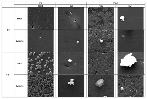
Figure 4. SEM micrographs of TCP and TCP-T samples after biomimetic study (bar = 5 µm).

Figure 4. SEM micrographs of TCP and TCP-T samples after biomimetic study (bar = 5 µm).

Table 1. EDX Ca/P ratio of TCP and TCP-T samples before and after 3 and 8 d of biomimetic study

Table 2. Chemical composition (at.%) and atomic ratios for TCP-T samples in dynamic and static conditions, determinated from XPS analysis

Table 3. Direct Ca/P, O/Ca and O(1s)II/O(1s) total ratio given by Lu HB et al.Citation18

Figure 5. O1s loss spectrum of TCP-T ceramic after 8 d in NCM and CM culture media in dynamic conditions. The O1s photoelectric peak is located at 532 eV. The area ratio between the two components of the loss spectrum (554 eV and 568 eV) are modified by the culture conditions indicating a modification of the ceramic phases. The two spectra are represented with the same ordinate scale.
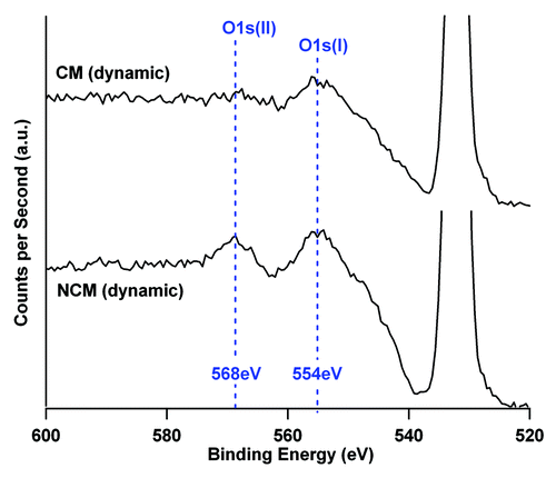
Figure 5. O1s loss spectrum of TCP-T ceramic after 8 d in NCM and CM culture media in dynamic conditions. The O1s photoelectric peak is located at 532 eV. The area ratio between the two components of the loss spectrum (554 eV and 568 eV) are modified by the culture conditions indicating a modification of the ceramic phases. The two spectra are represented with the same ordinate scale.

Table 4. Identification of CaP phases for TCP-T samples after normalization from values given by Lu et al.Citation18

Figure 6. Fluorescence micrographs of actin cytoskeleton of SaOs-2 cells adhered after 4 d of culture on TCP and TCP-T samples in static and dynamic condition.
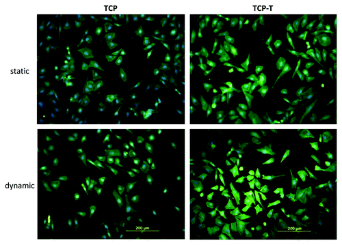
Figure 6. Fluorescence micrographs of actin cytoskeleton of SaOs-2 cells adhered after 4 d of culture on TCP and TCP-T samples in static and dynamic condition.

Figure 7. (A) Proliferation of SaOs-2 cells cultured on TCP and TCP-T samples in static and dynamic conditions. (B) Alkaline phosphatase activity of SaOs-2 cells cultured on TCP and TCP-T samples in static and dynamic conditions. (A) The asterisk (*) denotes a statistical difference between TCP and TCP-T in dynamic conditions and the asterisk (#) indicates a statistical difference between TCP and TCP-T in static condition after 7 d of culture (p < 0.05). (B) The asterisk (*) indicates a significant difference in ALP activity after 7 d between TCP-T in dynamic mode and TCP in dynamic and static mode (p < 0.05). Error bars represent means ± SD.
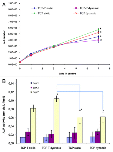
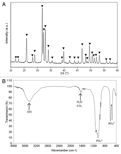
Figure 7. (A) Proliferation of SaOs-2 cells cultured on TCP and TCP-T samples in static and dynamic conditions. (B) Alkaline phosphatase activity of SaOs-2 cells cultured on TCP and TCP-T samples in static and dynamic conditions. (A) The asterisk (*) denotes a statistical difference between TCP and TCP-T in dynamic conditions and the asterisk (#) indicates a statistical difference between TCP and TCP-T in static condition after 7 d of culture (p < 0.05). (B) The asterisk (*) indicates a significant difference in ALP activity after 7 d between TCP-T in dynamic mode and TCP in dynamic and static mode (p < 0.05). Error bars represent means ± SD.