Figures & data
Figure 1. Schematic overview of the events taking place in cancer tissues and some of the strategies for providing a rational nanoparticulate drug delivery system with both passive and active targeting. Nanoparticulate delivery systems can be used to target and accumulate anticancer drugs to tumor tissues (e.g., brain, lung, stomach and intestine) by passive targeting; making use of the leaky vasculature and the EPR effect to reach the cancer cells. Alternatively, nanoparticulate delivery systems can also be used to target and accumulate anticancer drugs to tumor tissues by active targeting; making use of the targeting moieties attached to the surface of the nanoparticulate systems to deliver drugs to pathological sites or to cross biological barriers based on molecular recognition processes to target the receptors of the cancer cells.
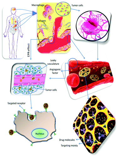
Figure 2. Phase contrast (A–D) and fluorescence (stained with Calcein AM) microscope images of HeLa cells incubated for 24 h with doxorubicin-loaded magnetic LiPSi, showing magnetically guided (H) and without guidance (J and K) delivery of doxorubicin. The position of each image relative to the external magnet is depicted in I). Scale bar for all images is 100 µm. Reprinted with permission from reference Citation48.
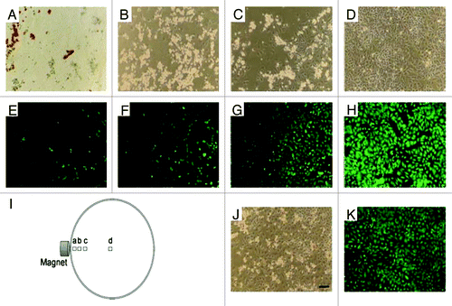
Figure 3. Schematic of a NIR light-triggered release of guest molecules from the pores of an aptamer-covered PSiO2-based nanovehicle. Reprinted with permission from reference Citation50.
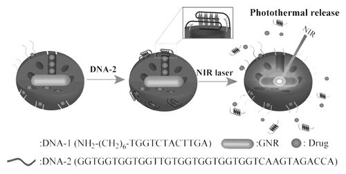
Figure 4. (A) Quantification of cellular uptake and apoptosis of different shaped PSiO2 by flow cytometry analysis of different prepared PSiO2 nanoparticles: sphere-shaped, NS (100 nm), short rod-shaped, NSR (240 nm) and long rod-shaped, NLR (450 nm). (B) Quantitative measurement (fluorescence) of particle numbers in cells (data are presented as mean ± s.d; statistical significance for the comparison of the number of internalized particles between different shaped particles, **p < 0.1). (C) Influence of different concentrations of shaped nanoparticles on early apoptosis of A375 cells. Reprinted with permission from reference Citation77.
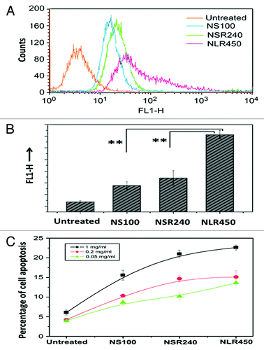
Figure 5. (A) In vivo imaging of mice injected peritumoral with poly(ethylene imine) (PEI)-PSiO2 nanoparticles ( = MSNPs) or FA-MSNPs. Images of the abdominal and dorsal area demonstrate accumulation of fluorescence in the bladder and in the tumors, respectively. Images of the abdominal area show elimination of fluorescence within 48 h after injections. (B) Ex vivo analyses (left) and quantification of fluorescence intensity (right) in organs from mice injected intravenous with FA-MSNPs. (C) Histological analysis of brain, kidney, spleen, liver, and lungs of untreated mice and FA-MSNPs-treated mice showed no morphological changes. PSiO2 nanoparticles accumulated in the tumors were biocompatible, biodegradable and eliminated through renal excretion. Reprinted with permission from reference Citation33.
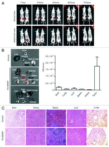
Figure 6. Conjugation of FA with PSiO2 nanoparticle showed improved endocytosis in HeLa cells. HeLa cells treated with PSiO2 nanoparticles at 10 µg/ml for 2 h and the extracellular binding of the nanoparticles was quenched with trypan blue (FITC, pristine FITC-labeled particle; FITC/PEI, PEI-functionalized FITC-labeled particle; FITC/PEI/FA, FA-conjugated PEI-functionalized FITC-labeled particle). Fluorescence microscopy was used to image FITC-labeled particles inside the cells and differential interference contrast microscopy for cellular morphology evaluations (A). Flow cytometry was used to detect the number of HeLa cells with endocytosed PSiO2 nanoparticles in control or trypan blue quenched cells (B). Reprinted with permission from reference Citation53.
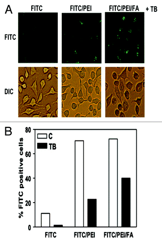
Figure 7. Confocal microscopy images after 6 h incubation of living HCT-116 colorectal cancer cells with FITC-galactose-modified PSiO2 nanoparticles ( = MSN-FITC-gal) at 37°C. Merged pictures of both section A and B indicated the co-localization (yellow) of FITC-nanoparticles (green) with lysosomal or endosomal markers, respectively. Reprinted with permission from reference Citation113.
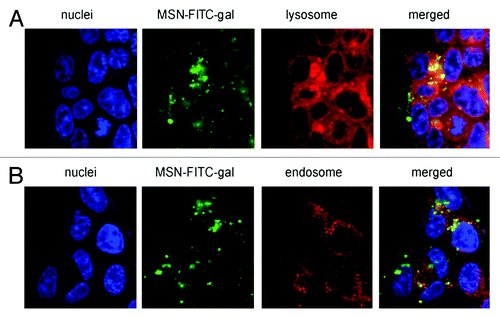
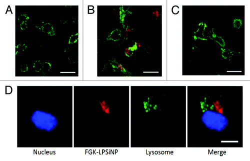
Figure 8. Fluorescence microscope images of mouse bone marrow derived dendritic cells treated with (A) LPSiNPs or (B) FGK-LPSiNPs for 1.5 h at 37°C. (C) 30 min pretreatment of the bone marrow-derived dendritic cells (green) with free FGK45 inhibits uptake of FGK-LPSiNPs incubated with the cells for 1.5 h at 37°C. FGK-LPSiNPs were detected by their intrinsic visible/near-infrared photoluminescence (red, λex = 405 nm and λem = 700 nm). The scale bars are 40 µm. (D) Distribution of FGK-LPSiNPs bone marrow-derived dendritic cells after 1.5 h incubation at 37°C. The lysosomes are stained in green (LysoTracker; Invitrogen), the nucleus in blue and FGK-LPSiNPs in red. The scale bar is 10 µm. Reprinted and modified with permission from reference Citation116.