Figures & data
Figure 1. Allosteric regulation of a hairpin ribozyme derived aptazyme by FMN:Citation9 FMN binding to the aptamer leads to increased activity. Reduction changes the molecular shape of FMN such that binding is inhibited. As a result, ribozyme activity is clearly decreased.
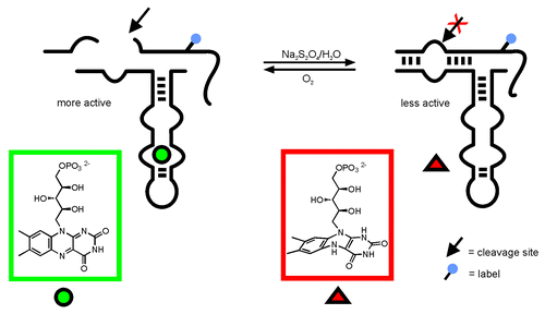
Figure 2. Secondary structure of the ypaA aptamer domain: Sites of successful ligation are indicated with arrows. AP marks the positions of 2-AP modification.
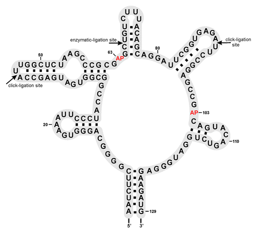
Figure 3. Enzymatic ligation of two fragments. (A) Preparative denaturing polyacrylamide gel of enzymatically ligated fragments. Bands were visualized by UV shadowing. Ligation reactions were conducted in a total volume of 20 µl with short (37 nt) or long (51 nt) DNA splint. The relation acceptor:splint:donor is given in brackets: Lane 1: dye-marker (~55 nt), lane 2: 5 µM acceptor, (1:1.5:2), short splint; lane 3: 5 µM acceptor, (1:1.5:2), long splint; lane 4: 10 µM acceptor, (1:0.5:1), short splint; lane 5: 10 µM acceptor, (1:0.5;1), long splint; lane 6: 10 µM acceptor, (1:1.5:2), short splint; lane 7: 10 µM acceptor, (1:1.5:2), long splint. See Supplementary Material for detail information. (B) refer to lane 7 in panel A: Ligation scheme (lane 7).
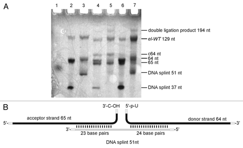
Figure 4. Synthesis of RNA-fragments for Click ligation. Preparation of 3′-alkyne building block (A); 5′-azid building block (B); 5′-alkyne building block (C); 3′-azid building block (D) See Supplementary Material for details.
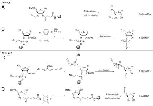
Figure 5. Strategies for Click ligation: (A) Click reaction of 3′-terminal 3′-alkyne with 5′-terminal azide resulting in 1,4-dimethylen tetrazol moiety; (B) Click reaction of 3′-terminal azide with 5′-terminal alkyne resulting in a more flexible tatrazol-linkage with n-butyl-bridge and phosphate moiety.
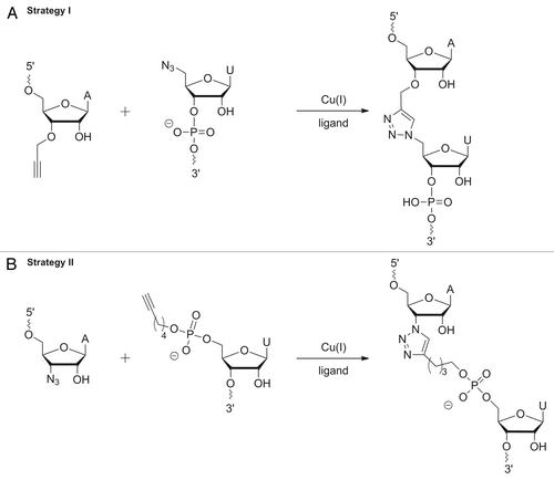
Figure 6. Preparation of the ypaA aptamer by Click ligation. Preparative denaturing PAA gels. Bands were visualized by UV shadowing: (A) Strategy I: 5′-terminal 45nt fragment; lane 2: RNA ladder, lane 3: ligation reaction using the three fragments and a full-length DNA splint as shown on the right. (B) Strategy II: ligation reaction using three fragments and a full-length DNA splint as shown on the right, lane 2: full-length aptamer wt-tr resulting from in vitro transcription, lane 3: ligation reaction using three fragments without splint as shown on the right, lane 4–7: single site ligations of two fragments out of the three (see Fig. S5 for details).
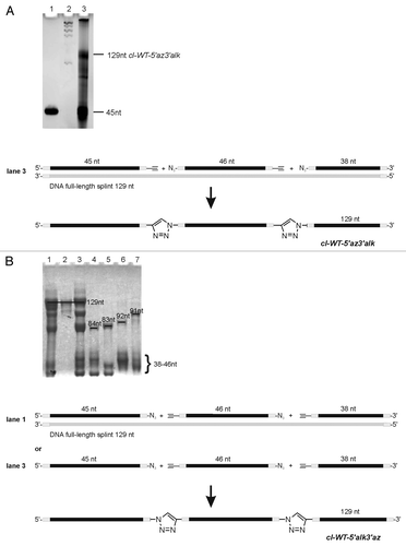
Figure 7. FMN fluorescence quenching curves: (A) Blue curve: FMN [0.1 µM]. FMN [0.1 µM] was incubated with cl-WT-5′alk3′az [0.15 µM] (red), cl-WT-5′az3′alk [0.15 µM] (purple), el-WT [0.15 µM] (yellow), tr-WT [0.15 µM] (green). (B) Blue curve: FMN [0.1 µM], red: cl-WT-5′alk3′az [0.15 µM] upon folding in the presence of FMN as folding mediator; (C) Blue curve: FMN [0.15 µM], red: upon incubation with el-A63AP [0.3 µM]; (D) blue curve: FMN [0.15 µM], red: upon incubation with el-A103AP [0.3 µM].
![Figure 7. FMN fluorescence quenching curves: (A) Blue curve: FMN [0.1 µM]. FMN [0.1 µM] was incubated with cl-WT-5′alk3′az [0.15 µM] (red), cl-WT-5′az3′alk [0.15 µM] (purple), el-WT [0.15 µM] (yellow), tr-WT [0.15 µM] (green). (B) Blue curve: FMN [0.1 µM], red: cl-WT-5′alk3′az [0.15 µM] upon folding in the presence of FMN as folding mediator; (C) Blue curve: FMN [0.15 µM], red: upon incubation with el-A63AP [0.3 µM]; (D) blue curve: FMN [0.15 µM], red: upon incubation with el-A103AP [0.3 µM].](/cms/asset/27003067-4e28-49b4-b86f-7aa22f7634a4/krnb_a_10928526_f0007.gif)
Table 1. FMN quenching assay, normalized fluorescence
Figure 8. Electrophoretic mobility gel-shift analysis of FMN binding to the ypaA aptamer. Bands were visualized by ethidium bromide staining: lane 1: free aptamer, lane 2: aptamer incubated with 1000-fold excess of FMN, lane 3: free aptamer, denatured prior to subjecting onto the gel, lane 4: aptamer, denatured prior to addition of a 1000-fold excess of FMN and subjecting onto the gel, lane 5: free FMN.
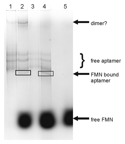
Figure 9. 2-AP fluorescence curves: (A) blue curve: FMN [20 µM], DTT [1 mM]; red: FMN [20 µM], DTT [1 mM], irridation with light (405 nm for 15 min); purple: FMN [20 µM], DTT [1 mM], irridation with light (405 nm for 15 min), oxygen. (B) blue curve: RNA [0.3 µM], DTT [1 mM]; red: RNA [0.3 µM], DTT [1 mM], irridation with light (405 nm for 15 min). (C) blue curve: el-A63AP [0.3 µM]; red: el-A63AP [0.3 µM] and FMN [0.6 µM]; (D) blue curve: el-A63AP [0.3 µM]; red: el-A63AP [0.3 µM] and FMN [0.6 µM]; yellow: el-A63AP [0.3 µM], FMN [0.6 µM] and DTT; purple: el-A63AP [0.3 µM], FMN [0.6 µM] and DTT, oxygen. (E) blue curve: el-A103AP [0.3 µM]; red: el-A103AP [0.3 µM] and FMN [0.6 µM]; (F) blue curve: el-A103AP [0.3 µM]; red: el-A103AP [0.3 µM] and FMN [0.6 µM]; yellow: el-A103AP [0.3 µM], FMN [0.6 µM], DTT and light (405 nm, 15 min); purple: el-A103AP [0.3 µM], FMN [0.6 µM] and DTT, oxygen.
![Figure 9. 2-AP fluorescence curves: (A) blue curve: FMN [20 µM], DTT [1 mM]; red: FMN [20 µM], DTT [1 mM], irridation with light (405 nm for 15 min); purple: FMN [20 µM], DTT [1 mM], irridation with light (405 nm for 15 min), oxygen. (B) blue curve: RNA [0.3 µM], DTT [1 mM]; red: RNA [0.3 µM], DTT [1 mM], irridation with light (405 nm for 15 min). (C) blue curve: el-A63AP [0.3 µM]; red: el-A63AP [0.3 µM] and FMN [0.6 µM]; (D) blue curve: el-A63AP [0.3 µM]; red: el-A63AP [0.3 µM] and FMN [0.6 µM]; yellow: el-A63AP [0.3 µM], FMN [0.6 µM] and DTT; purple: el-A63AP [0.3 µM], FMN [0.6 µM] and DTT, oxygen. (E) blue curve: el-A103AP [0.3 µM]; red: el-A103AP [0.3 µM] and FMN [0.6 µM]; (F) blue curve: el-A103AP [0.3 µM]; red: el-A103AP [0.3 µM] and FMN [0.6 µM]; yellow: el-A103AP [0.3 µM], FMN [0.6 µM], DTT and light (405 nm, 15 min); purple: el-A103AP [0.3 µM], FMN [0.6 µM] and DTT, oxygen.](/cms/asset/efacd229-e47c-4c41-bfdb-851e989cbb1e/krnb_a_10928526_f0009.gif)
