
 ?Mathematical formulae have been encoded as MathML and are displayed in this HTML version using MathJax in order to improve their display. Uncheck the box to turn MathJax off. This feature requires Javascript. Click on a formula to zoom.
ABSTRACT
The combustion of various fuels results in the release of firebrands during wildland-urban interface (WUI) fires. Firebrands represent a hazard, since the release of firebrands may lead to multiple ignitions at locations distant from the original combustion source. A newly developed experimental protocol using a non-reacting heater was used to simulate a firebrand. A direct comparison of this simplified non-reacting heater setup was undertaken to realistic fuel bed ignition to actual firebrand showers. Firebrand showers were generated using a custom experimental setup developed for this investigation. The novelty of this research is a detailed comparison for the first time to fuel bed ignition from non-reacting heaters to actual firebrand showers, for the same fuel bed type. The focus here is on smoldering ignition (SI) of the fuel beds, as this is seen as a complex and least understood aspect of firebrand ignition of actual WUI fires. Results indicate that the overall phenomenology of the ignition process is different between a non-reacting cartridge heater and a shower of firebrands. Complicated smoldering ignition phenomena of fuel beds by firebrand showers cannot be simulated by a simple non-reacting heater.
Introduction
The wildland-urban interface (WUI) fire problem is continuing to be challenging across the world. For many years, this has been seen as a problem mainly in the USA and, in particular, in the USA state of California (CALFIRE Citation2018, Citation2021). Yet, due to continued changes in global climate, many areas not often associated with a WUI fire problem are now being forced to deal with this new challenge (EFFIS Statistics Portal Citation2024; Abatzoglou and Williams Citation2016). Parts of Northern Europe now possess a WUI fire problem (Ganteaume et al. Citation2021). The recent WUI fires in Hawaii stunned many across the globe (Hassan and Betts Citation2023). When WUI fires occur, massive conflagrations can erupt that quickly overtake emergency resources.
Post-fire investigation studies have reported that firebrands are the usual culprit to produce ignitions on both vegetative and human-made fuels (Jackson Citation2015; Teague, Pascoe, and McLeod Citation2010). Firebrands are released from the combustion of various fuels during WUI fires. A further complex aspect of these WUI fire ignitions is that firebrands are often seen in the form of showers that rain down fuels in WUI communities. In general, during WUI fires, fuels are exposed to time-dependent, multiple ignition points (Manzello and Foote Citation2014; Manzello et al. Citation2020).
Recently, various research groups have considered the use of non-reacting heaters to try to simulate firebrand ignition via flaming ignition of fuel beds despite the difference between firebrands and non-reacting heaters (Alvarez et al. Citation2023; Bean and Blunck Citation2021; Hernandez et al. Citation2018; Rivera et al. Citation2021; Zhu and Urban Citation2023). While these studies are important and add improved understanding to this complex problem, to date there have been no attempts to actually compare the details of ignition to firebrand showers. A further complication is that all the non-reacting heater setups are different among different research groups as well, making detailed comparisons, even among the non-reacting heater setups, very difficult.
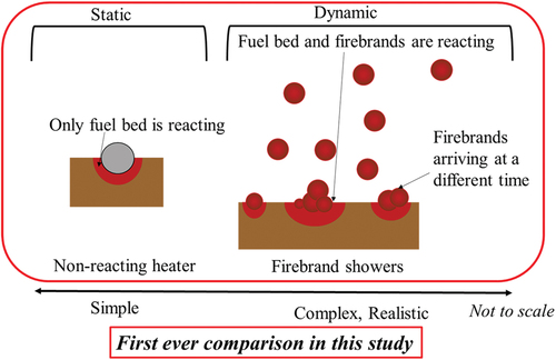
In this study, a new, very simple experimental apparatus has been constructed using a non-reacting heater to study fuel bed ignition. These findings are then compared to complex, realistic experiments conducted to apply firebrand showers using the same fuel beds to the non-reacting heater studies for the first time (). A comparison was undertaken between a non-reacting heater and firebrand showers. Specifically, it is known that a single firebrand ceases combustion seconds after landing on a fuel bed under no wind, whereas a non-reacting heater can emit heat as long as it is activated. Thus, when comparing a non-reacting heater to an actual single firebrand, the heating lifetime is totally different. Considering firebrand showers take time to ignite fuel beds, as do a non-reacting cartridge heater, this important phenomenology was considered as the technical basis for a meaningful comparison. A major difference with prior non-reacting heater studies is a focus on smoldering ignition (SI) of the fuel beds, as this is seen as a complex and least understood aspect of firebrand ignition of actual WUI fires (Santoso et al. Citation2019).
Figure 1. A comparison to fuel bed ignition by a non-reacting heater and firebrand showers.
Experimental description
Experiments with a non-reacting heater
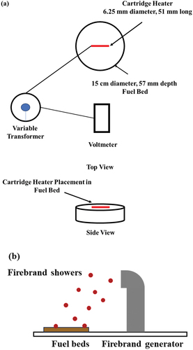
The experimental setup consisted of a cartridge heater coupled to a variable transformer to adjust the applied voltage shown in . The surface of a cartridge heater for this experiment is SUS304. It is important to note that experiments with a non-reacting cartridge heater were performed with no wind applied, to match the condition of past non-reacting cartridge heater studies (Alvarez et al. Citation2023; Bean and Blunck Citation2021; Hernandez et al. Citation2018; Rivera et al. Citation2021; Zhu and Urban Citation2023). Past non-reacting heater studies suggest that wind is not needed to simulate fuel bed ignition. The reality is that wind would affect fuel bed ignition as the pyrolysis gas would be affected by wind, which could interfere with the non-reacting heater to act as the piloted ignition source. In the case of ignition by firebrand showers, as also observed in actual wildland/WUI fires, wind is important in the fuel bed ignition process. As described later, in the case of firebrand showers, these do not act as the piloted source of the fuel beds. Thus, a decision was made to apply no wind for the non-reacting heater, as all the past non-reacting heater studies do not use wind. The cartridge heater was 6.25 mm in diameter and 51 mm in length. The size of the cartridge heater was selected to be representative of a firebrand generated from tree combustion and a real WUI fire (Manzello and Foote Citation2014). The fuel bed consisted of a stainless-steel cylindrical container, 15 cm in diameter and 57 mm in depth. It was filled with Douglas-fir wood pieces. The size of each Douglas-fir wood piece was 7.9 mm × 7.9 mm × 12.7 mm (in length). The Douglas-fir wood pieces were oven-dried, and the temporal evolution of mass loss was determined as a function of time until completely dried. Then, the Douglas-fir wood pieces were cooled down to room temperature. At the time of the experiments, the fuel bed moisture content was estimated to be 1% (dry basis). The bulk density of fuel beds was 330 kg/m3 (6 kg/m3), and the density of each wood piece was 630 kg/m3. A typical experiment consisted of selecting the appropriate voltage on the variable transformer, the voltage was then confirmed with a volt meter, and the heater was allowed to stabilize. After this period, the cartridge heater was placed onto the fuel bed and the ignition delay time was recorded. The cartridge heater was placed on the surface of the Douglas-fir fuel beds. The Douglas-fir fuel bed was prepared such that it was randomly packed. It is intentional so that the heater was randomly touching the fuel beds. These conditions were the same for experiments with firebrands. In these experiments, the time to reach smoldering ignition (SI) was of interest and was defined as the presence of glowing combustion in the fuel bed coupled with smoke generation. If the applied voltage was above a certain threshold, flaming ignition was observed. If 15 minutes have passed without ignition, the experiment was considered “no ignition” as experiments with firebrand showers (described in section 2.2) showed smoldering ignition within 15 minutes. The experiments were repeated multiple times for each condition.
Figure 2. Experimental setting for (a) Ignition with a cartridge heater and (b) Ignition with firebrand showers.
Experiments with firebrand showers
To perform experiments using firebrand showers, a custom firebrand generator experimental apparatus was utilized (Suzuki and Manzello Citation2021a) shown in . Experiments were performed in the wind facility, with 4 m/s applied wind for the safe operation of the experimental apparatus. In this experimental series, the external heat was not provided. The firebrand generator works by loading a certain mass of wood fuel into the device at precise intervals. Selected fuel loading rates for this experimental series were 40 g/min, 60 g/min and 80 g/min. Inside the firebrand generator, there is a fine mesh that suspends the fuel, where it is ignited using a propane burner. The firebrand generator is attached to a variable pressure blower that provides both airflow for combustion and also enables the produced firebrands to be lofted. Depending on how the flow velocity is selected inside the firebrand generator, firebrands exit in either a glowing combustion or flaming combustion state. In this work, all the generated firebrands were set to be in a state of glowing combustion. The same Douglas-fir wood pieces, as described for the non-reacting cartridge heater experiments, were used as the target fuel bed. The size of fuel beds was 30 cm x 30 cm x 5 cm, and the fuel bed was located downwind from the firebrand generator. The firebrand generator apparatus was operated to make showers of firebrands similar to those from a real WUI fire, and the average projected area of these firebrands was 2.0 ± 1.0 cm2 (Manzello and Foote Citation2014). The baseline experiments were performed to understand the mass and the size of firebrands produced from the firebrand generator. Produced firebrands were collected and oven-dried. A picture of a firebrand was taken with a caliper, and the mass of each firebrand was measured with a scale. The projected area of a firebrand was determined following the procedure (Suzuki and Manzello Citation2021b) and analyzed. The average mass of a firebrand (after combustion) was 0.05 g ( 0.005 g). Several experiments were performed for the same condition.
Theoretical approach
Theoretical approaches are developed to understand the experimental findings. With the fuel bed as a system, an energy balance yields:
where is the total heat in the fuel bed system,
is the net heat contributed to the fuel beds from the firebrands, and
is the total heat loss from fuel beds to the air. As fuel beds were completely dried for all the experiments, the term denoting the energy to remove the fuel bed moisture is not included. It is also important to note that in the past studies (Suzuki and Manzello Citation2023),
was not considered due to the imposed radiant heat from the outside source during the experiments or due to the assumption of continuous heating from firebrand showers at the ignition spot.
To ignite the fuel beds, is required where
is the energy required for fuel bed ignition. Assuming ignition occurs when the temperature of the fuel beds reaches the ignition temperature
,
may be described as follows:
where is the bulk density of the fuel beds,
is the specific heat capacity of fuel beds (wood),
is the initial temperature of the fuel bed (room temperature), and V is the volume of the fuel bed involved with the ignition.
Non-reacting heater
The heat generated from a cartridge heater was considered as thermal radiation for this study. In reality, due to the contact between a non-reacting heater and the fuel bed, there would be conductive heat transfer. The cartridge heater heat flux was calculated at different temperatures by using the following equation.
where is the heat flux from a cartridge heater,
is the emissivity,
is the Stefan-Boltzmann coefficient, and
is the measured temperature of the cartridge heater.
was employed based on information provided by the manufacturer. In this work, only half of the cartridge heater contacted to the fuel bed, therefore, EquationEquation (3)
(3)
(3) may be written as the following:
where is the surface area of the cartridge heater in contact with the fuel bed, and
is the time to fuel bed ignition. As the heat from the cartridge heater was imposed to the fuel beds during the experiments,
is not considered. Thus, substituting EquationEquations (2)
(2)
(2) and (Equation4
(4)
(4) ) into EquationEquation (1)
(1)
(1) yields the following:
Firebrand showers
The temperature of a firebrand () is not as simple as a cartridge heater. It changes as a function of time, the combustion state, or the accumulation state. To express this, the following is applied:
where describes the heat generated from the combustion of firebrands,
describes the heat loss to the ambient atmosphere, and
describes the heat contributed to the fuel bed at time
(
) from firebrands. Firebrands involved with SI in this study are not a single firebrand but many firebrands. An important consideration in this study should be whether the number of firebrands or the time to heat the fuel beds from firebrands contribute to the SI at a given spot.
Assuming the number of firebrands plays a role to SI, using the heat contribution from a single firebrand, defined as , and the heat contribution from i-th firebrand landing on the fuel bed, defined as
. Ignition may occur before all the firebrands burn out, when the i-th firebrand lands on the fuel bed at time
and
where
is the burnout time of a firebrand. In this case, the i-th firebrand does not fully contribute to the fuel bed. As firebrands that arrive at the SI spot can be considered not to contribute fully to the SI prior to the onset of SI,
can be described as:
where n is the number of firebrands involved with ignition. In EquationEquation (7)(7)
(7) , the interaction between neighboring firebrands is not considered as the past research on the interaction between neighboring firebrands focused on a large number of firebrands and there are no studies about how the small number of glowing firebrands may change the burning behavior of firebrands. Combining EquationEquation (6)
(6)
(6) and EquationEquation (7)
(7)
(7) , yields:
where is the heat contribution from a single firebrand at time
,
is the heat of combustion of a firebrand,
is the mass of a given firebrand at time
,
is the convection coefficient of a firebrand, and
is the firebrand area exposed to the wind. In EquationEquation (8)
(8)
(8) ,
is the mass of a given firebrand at time
, 1 second later from time
. EquationEquation (8)
(8)
(8) considers a single firebrand’s heat contribution upon landing to burn out. In reality, ignition may occur before all the firebrands burn out when the i-th firebrand lands on the fuel bed at time
and
. In this case, the i-th firebrand does not fully contribute to the fuel bed. For simplicity, it is assumed that all firebrands equally (fully) contribute heat to the fuel bed.
In a simple form, assuming the is constant,
can be described as (Kasymov et al. Citation2021; Yin et al. Citation2012):
where describes the mass loss of a firebrand. Thus, combining:
If the heating time is important regardless of the number of firebrands at time , it can be assumed that the heat contributed to the fuel beds from firebrands is constant from the moment firebrands arrive at the SI spots till burnout, using EquationEquations (8)
(8)
(8) and (Equation9
(9)
(9) ),
Thus,
where is the effective heating time. As it is assumed that
is constant,
can assume to be constant. Compared with EquationEquation (4)
(4)
(4) ,
for cartridge heater can be considered
for firebrand showers.
In the fuel bed, the following applies:
where is the radiative heat loss from fuel beds to the air, and
is the convective heat transfer (cooling) to the fuel beds. In past studies (Suzuki and Manzello Citation2023),
was not considered due to the imposed radiant heat flux from the outside source during the experiments or due to the assumption of continuous heating from firebrand showers at the ignition spot.
where is the temperature of the fuel bed,
is the convective heat transfer coefficient of the fuel bed,
is the fuel bed area exposed to wind, and
is the view factor. As the temperature of the fuel bed changes due to heat contribution from the firebrand shower, it is difficult to solve this without all the knowledge of those parameters. Thus,
will be calculated later based on the experimental data. Here, defining
and assuming the heat loss from the fuel beds to the air is not considered when the firebrands exist on the spot, EquationEquation (14)
(14)
(14) can be written as:
Substituting EquationEquations (2)(2)
(2) , (Equation10
(10)
(10) ), and (Equation15
(15)
(15) ) into EquationEquation (1)
(1)
(1) yields the following for the firebrand number-based approach:
where
Or substituting EquationEquations (2)(2)
(2) , (12), and (Equation15
(15)
(15) ) into EquationEquation (1)
(1)
(1) yields the following for the effective heating time approach:
Results and discussions
Non-reacting heater
When using the non-reacting cartridge heater, the voltage was the parameter that was varied. The variation of applied voltage resulted in a change in the non-reacting cartridge heater temperature, resulting in a given heat flux that the fuel bed was exposed to once the heater was placed onto the fuel bed. The temperature of the cartridge heater was measured by K-type thermocouples, and the heat fluxes were calculated from the temperature measurement. The heat flux was also measured using the heat flux gauge at a certain distance from the surface of the cartridge heater at different voltages for confirmation. displays the measured smoldering ignition delay time as a function of the applied non-reacting cartridge heater heat flux. Heat flux was varied from 7.6 kW/m2, 9.2 kW/m2, 10.9 kW/m2, 12.9 kW/m2, 15.2 kW/m2, 17.7 kW/m2, and 21.1 kW/m2. Smoldering ignition was defined as intense smoke production and glowing combustion in the fuel bed. As the non-reacting cartridge heater heat flux was increased from 10.9 kW/m2, 12.9 kW/m2, to 15.2 kW/m2, the smoldering ignition delay time decreased. Eventually, smoldering ignition was no longer possible, and for higher heat flux levels (17.7 kW/m2, 21.1 kW/m2), flaming ignition was observed. For low heat flux levels (7.6 kW/m2, 9.2 kW/m2, and 10.9 kW/m2), no ignition events were observed within 15 min. For the data in , each data point represents the average and the error bars are the standard deviation. For comparison, the smoldering ignition delay time was calculated from EquationEquation (5)(5)
(5) using and plotted in . Better agreement was achieved for heat flux levels greater than 12 kW/m2, while the agreement was poor for the lower heat flux levels. This is expected due to the simplified assumption of EquationEquation (2)
(2)
(2) and the exclusion of conductive heat transfer. Sensitivity analysis, see , on EquationEquation (5)
(5)
(5) , which defined sensitivity of
as one, demonstrates the effect of all the parameters on EquationEquation (5)
(5)
(5) . This shows that the initial temperature is relatively insensitive while the ignition temperature is more sensitive. The rest of the parameters have similar sensitivity. In this study, the initial temperature was controlled, but the ignition temperature of fuel beds was assumed to be the same for all the cases. As it takes longer to ignite at the lower heat flux, the assumption of EquationEquation (2)
(2)
(2) will have an impact on the calculation as well as the assumed ignition temperature may be different.
Figure 3. Smoldering ignition (SI) delay time vs heat flux from a cartridge heater.
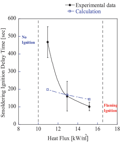
Figure 4. Sensitivity analysis on EquationEquation (5)(5)
(5) .
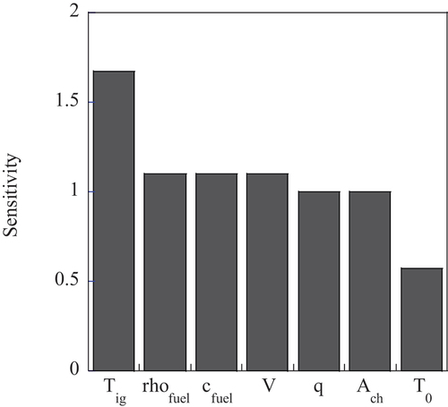
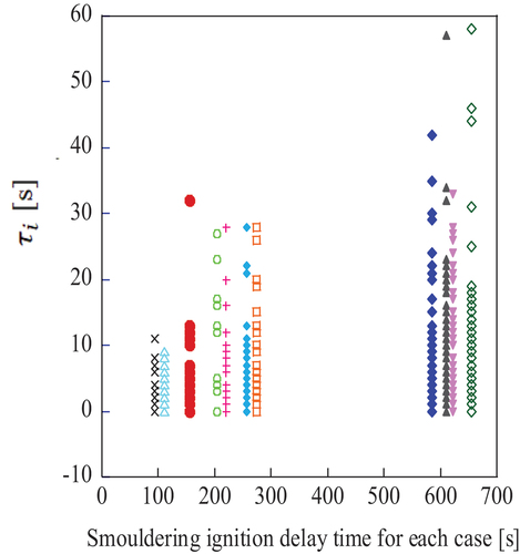
Figure 5. Intervals of arrival time of firebrands vs smoldering ignition delay time, for given SI spot.
Firebrand showers
The time to ignition by firebrands and the time when each firebrand landed on the SI spot was observed via video recording as described in Suzuki and Manzello (Citation2021a). In the case of applying firebrand showers to the same fuel used for the non-reacting cartridge heater experiments, the overall phenomenology of the fuel bed ignition was far different. When firebrand showers are applied, after a certain number of glowing firebrands were observed at a given spot in the fuel bed, smoldering ignition was eventually observed. Under no experimental conditions was flaming ignition observed in an instantaneous manner, as was seen for the non-reacting cartridge heater experiments. Rather, once smoldering ignition was observed, these smoldering ignitions were observed to eventually transition to flaming ignition. The transition from smoldering ignition to flaming ignition is a complex process (Santoso et al. Citation2019). In order to compare ignition events to the non-reacting cartridge heaters, in this work, the ignition delay time to reach smoldering ignition was compared. At each SI spot, was carefully recorded.
Table 1. Data for EquationEquation (5)(5)
(5) .
displays how the smoldering ignition delay time for a given ignition spot was influenced by the intervals of arrival time of firebrands, , where
is defined as
. The arrival time
is defined as the time i-th firebrand arrived at the given SI spot, and thus, the
, the intervals of the arrival time of firebrands, can be considered the arrival time difference between an i-th firebrand and an (i + 1)-th firebrand. Experimental observation revealed that several firebrands arrived at the ignition spot at the same time or within several seconds. In some instances, there were relatively long time periods where no firebrands arrived, as shown in . displays the variation of
, and also shows that the value of the time,
, ranged from 0 second to 58 seconds but in most cases less than 10 seconds. For experiments with firebrand showers, both the number of firebrands that arrive at a given ignition spot as well the time difference for how these firebrands arrive were important to understand the SI events. As may be seen, the ignition delay time is greatly influenced by how quickly repeated firebrands arrive at a given SI spot.
Figure 6. Calculated heat contribution from a firebrand to the fuel bed.
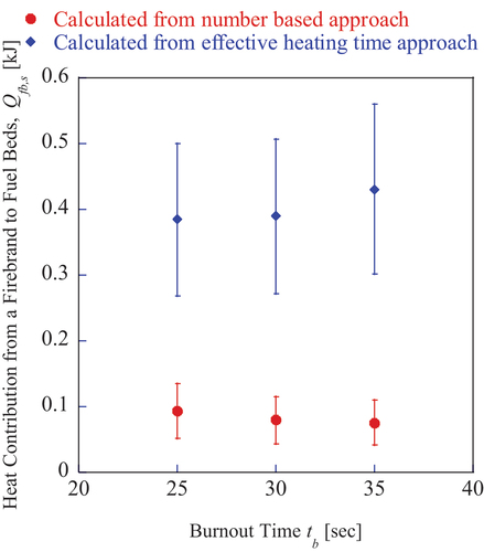
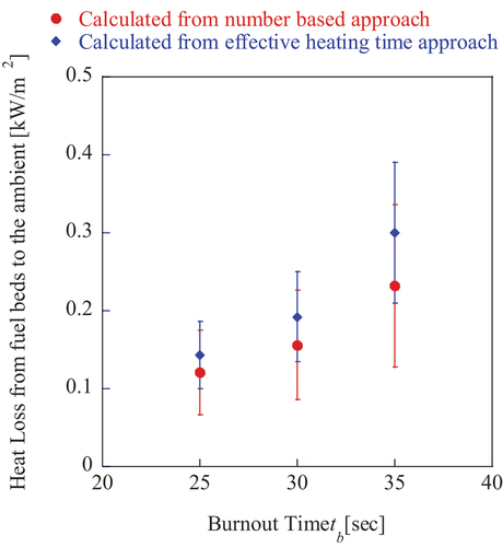
Figure 7. Calculated heat loss from fuel beds to the air.
The heat contribution of a firebrand to the fuel bed is important to understand the SI of a given spot. displays the calculated energy as a function of firebrand burnout time based on experiments with firebrand showers. From EquationEquation (16)(16)
(16) and (Equation18
(18)
(18) ), a regression model was used to calculate
, B for the number-based approach (EquationEquation (16)
(16)
(16) ), and
and B for effective heating time approach, using the experimental data. The approach is similar to the past studies (Suzuki and Manzello Citation2023), but in this study, no external heat was applied. In the case of the effective heating time approach, the obtained
was multiplied by the corresponding burnout time for comparison in . Selected burnout time was 25 seconds, 30 seconds, and 35 seconds, based on experimental observations. Different firebrand burnout times were considered to demonstrate the important trends. The R2 value for the regression model is shown in . In , a direct comparison is provided between the number-based approach, in EquationEquation (16)
(16)
(16) , and the effective heating time approach, in EquationEquation (18)
(18)
(18) . Overall, the heat contribution from a firebrand to the fuel beds,
, was on the lower side of reported data in the past (Suzuki and Manzello Citation2023). The calculated heat contribution,
, for the effective heat approach was overall larger than the one calculated from the number-based approach, due to the interval of arrival time of firebrands being less than the burnout time for most of the firebrands. As the burnout time increased, the heat contribution from a firebrand to the fuel beds increased slightly or remained similar for the effective heat time approach and decreased for the number-based approach. The reason for the increase in the heat contribution from a firebrand to the fuel beds for the effective heat time approach is that
was multiplied by the burnout time to calculate
, and
was decreased when the burnout time increased, which resulted in the almost constant or slightly increased
. The R2 value becomes smaller as the burnout time increases and the R2 value for the number-based approach is smaller than that for the effective heating time approach. Uncertainties of the heat contribution from a firebrand to the fuel bed for the effective heating approach increased as it was multiplied by the burnout time.
Table 2. R2 value for regression model for .
displays the calculated heat loss from the fuel beds to the ambient, using the number-based approach and the effective heating approach. All the data are plotted as a function of firebrand burnout time. As may be expected, both the magnitude and overall trends in the heat loss from the fuel beds were similar. It is important to note that the magnitude of heat loss from the fuel beds to the ambient was greater using the effective heating approach. From , the heat loss ratio, the ratio of the total heat from firebrands to the fuel to the total heat loss from the fuel beds to the ambient, to the firebrand heat contribution to the SI spot was calculated when firebrands do not exist at the SI spot for certain duration of the time. When considering the number-based approach, the heat loss ratio to the heat contribution of a firebrand was calculated to be 3%, 6%, and 10% (burnout time 25 seconds, 30 seconds, and 35 seconds, respectively) for a given spot defined in this study. For the effective heating time approach, 1%, 1%, and 2% (burnout time 25 seconds, 30 seconds, and 35 seconds, respectively). This ratio for the effective heating time approach is lower than the one for the number-based approach due to the higher heat contribution from a firebrand for the former approach. It should be noted that due to the assumption introduced for EquationEquation (15)(15)
(15) , the heat loss ratio here is considered a constant value. In reality, the heat loss changes are based on the fuel bed temperature. Nonetheless, this is important in that the intermittent arrival of firebrands, the time when no firebrands exist on the SI spot, plays an important role for smoldering ignition delay time. The absence of firebrands on the (eventual) SI spot lowers the temperature of the fuel beds. In addition, under the wind, the produced pyrolyzate may not be produced due to the temperature change but also be blown away, thus extending the smoldering ignition time. The exact effect of wind is unknown at this stage, and further investigation will be required.
Comparison between a non-reacting heater and firebrand showers for the smoldering ignition delay time
displays, for the first time, the smoldering ignition delay time between a non-reacting cartridge heater and firebrand showers. The heat flux from firebrand showers was calculated as a heat flux from a single firebrand in firebrand showers, using the data shown in . Due to the value of the heat flux from a firebrand, only the value calculated from the number-based approach is shown in . The heat flux from a firebrand was within a good agreement with the literature (Bearinger et al. Citation2021; Manzello, Park, and Cleary Citation2009). There is a great difference in the SI ignition behaviors between a non-reacting heater and firebrand showers. Using a non-reacting heater does not reproduce SI ignition behaviors as compared to using a more realistic shower of firebrands, as observed in actual WUI fires. In particular, firebrand showers show a broad range of SI ignition delay times. In addition, if a non-reacting heater was used to represent firebrands, for the fuel bed used in the study, it would incorrectly predict that there is no SI for heat flux levels greater than 15 kW/m2.
Figure 8. Comparison of smoldering ignition delay time vs heat flux between ignition from a non-reacting cartridge heater to firebrand showers.
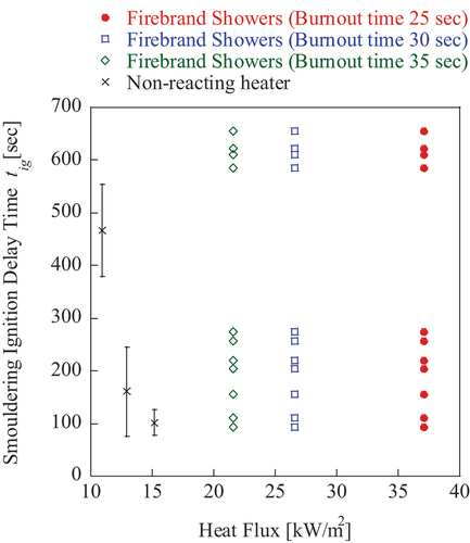
These differences are related to the phenomenology of the ignition process between a shower of firebrands and a non-reacting cartridge heater. It is the accumulation of firebrands that results in the SI of fuel beds and these SI transition to flaming ignition (Suzuki and Manzello Citation2021a). As indicated, when directly comparing the ignition of the same fuel bed to firebrand showers, and a non-reacting cartridge heater, under no conditions are instantaneous flaming ignitions observed.
Conclusions
Firebrand ignition of fuel beds in wildland-urban interface (WUI) fires remains a perplexing, difficult problem of global significance. It has been proposed by various authors to consider the use of non-reacting heaters to simulate firebrands to study fuel bed ignition. In the present study, the authors have developed a new experimental setup using non-reacting heaters to study fuel bed ignition. The results were then compared with experiments using actual firebrand showers, using another experimental setup developed for the work. A detailed comparison is presented, for the first time, to fuel bed ignition from non-reacting heaters to actual firebrand showers. Theoretical formulations were developed. The key findings were that the overall physical process of ignition was different, using the same fuel bed type. When a non-reacting cartridge heater was utilized, either smoldering ignition or instantaneous flaming ignition was observed in the fuel beds. For firebrand showers, smoldering ignition was observed, and this transitioned to flaming ignition. Under no conditions was instantaneous flaming ignition observed for firebrand showers applied to fuel beds. In this study, a non-reacting heater could not reproduce the complex and important smoldering ignition behaviors produced in fuel beds when the firebrand showers were applied. When investigating firebrand ignition in WUI fires, it is important to understand that a non-reacting heater is different than firebrand showers.
Nomenclature
Table
Author Contribution Statement
SS designed research, performed research, analyzed the data, and wrote the paper.
SLM designed research, performed research, analyzed the data, and wrote the paper.
Acknowledgments
The authors appreciate the help of Yuki Hara (TokyoTech) for calibrating a non-reacting heater for experiments.
Disclosure statement
No potential conflict of interest was reported by the author(s).
Correction Statement
This article has been corrected with minor changes. These changes do not impact the academic content of the article.
References
- Abatzoglou, J. T., and A. P. Williams. 2016. Impact of anthropogenic climate change on wildfire across western US forests. Proc. Natl. Acad. Sci. USA 113 (42):11770–75. doi:10.1073/pnas.1607171113.
- Alvarez, C., G. Moreno, F. Valenzuela, J. I. Rivera, F. Ebensperger, P. Reszka, and A. Fuentes. 2023. Use of an electric heater and as an idealized firebrand to determine ignition delay time of Eucalyptus globulus leaves. Fire Saf. J. 141:103923. doi:10.1016/j.firesaf.2023.103923.
- Bean, D., and D. Blunck. 2021. Sensitivities of porous beds and plates to ignition by firebrands. Front. Mech. Eng. 7:653810. doi:10.3389/fmech.2021.653810.
- Bearinger, E. D., J. L. Hodges, F. Yang, C. M. Rippe, and B. Lattimer. 2021. Localized heat transfer from firebrands to surfaces. Fire Saf. J. 120:103037. doi:10.1016/j.firesaf.2020.103037.
- Boonmee, N., and J. Quintiere. 2002. Glowing and flaming autoignition of wood. Proc. Combust. Inst. 29 (1):289–96. doi:10.1016/S1540-7489(02)80039-6.
- CALFIRE. 2018. Incident archive. Accessed May 28, 2024. https://www.fire.ca.gov/incidents/2018/.
- CALFIRE. 2021. Incident archive. Accessed May 28, 2024. https://www.fire.ca.gov/incidents/2021/.
- EFFIS Statistics Portal. Accessed May 28, 2024. https://effis.jrc.ec.europa.eu/apps/effis.statistics/.
- Ganteaume, A., R. Barbero, M. Jappiot, and E. Maillé. 2021. Understanding future changes to fires in southern Europe and their impacts on the wildland-urban interface. J. Saf. Sci. Resilience 2 (1):20–29. doi:10.1016/j.jnlssr.2021.01.001.
- Hassan, A., and A. Betts. Maui fires latest: Lahaina reopens to residents. New York Times. Accessed September 29, 2023 Accessed May 28, 2024. https://www.nytimes.com/article/maui-wildfires-hawaii.html.
- Hernandez, N., A. Fuentes, J. L. Consalvi, and J. C. Elicer-Cortes. 2018. Spontaneous ignition of wildland fuel by idealized firebrands. Exp. Therm. Fluid Sci. 95:88–95. doi:10.1016/j.expthermflusci.2018.01.037.
- Jackson, K. 2015. Case study of the 2015 hidden pines wildland-urban interface fires in Bastrop Texas. Bastrop, Texas, USA: Bastrop County Office of Emergency Management.
- Kasymov, D. P., M. V. Agafontsev, V. A. Tarakanova, E. L. Loboda, P. S. Martynov, K. E. Orlov, and V. V. Reyno. 2021. Effect of wood structure geometry during firebrand generation in laboratory scale and semi-field experiments. J. Phys.: Conf. Ser 1867 (1):012020. doi:10.1088/1742-6596/1867/1/012020.
- Manzello, S. L., and E. I. D. Foote. 2014. Characterizing firebrand exposure from wildland–urban interface (WUI) fires: Results from the 2007 angora fire. Fire Technol. 50 (1):105–24. doi:10.1007/s10694-012-0295-4.
- Manzello, S. L., S. H. Park, and T. G. Cleary. 2009. Investigation on the ability of glowing firebrands deposited within crevices to ignite common building materials. Fire Saf. J. 44 (6):894–900. doi:10.1016/j.firesaf.2009.05.001.
- Manzello, S. L., S. Suzuki, M. J. Gollner, and A. C. Fernandez-Pello. 2020. Role of firebrand combustion in large outdoor fire spread. Prog. Energy Combust. Sci. 76:100801. doi:10.1016/j.pecs.2019.100801.
- Peters, B., and C. Bruch. 2003. Drying and pyrolysis of wood particles: Experiments and simulation. J. Analytical Appl. Pyrolysis 70 (2):233–50. doi:10.1016/S0165-2370(02)00134-1.
- Rivera, J., N. Hernandez, J. L. Consalvi, P. Reszka, J. Contreras, and A. Fuentes. 2021. Ignition of wildland fuels by idealized firebrands. Fire Saf. J. 120:103036. doi:10.1016/j.firesaf.2020.103036.
- Santoso, M., E. Christensen, J. Yang, and G. Rein. 2019. Review of transition from smoldering to flaming combustion in wildfires. Front. Mech. Eng. 5:49. doi:10.3389/fmech.2019.00049.
- Suzuki, S., and S. L. Manzello. 2021a. Investigating coupled effect of radiative heat flux and firebrand showers on ignition of fuel beds. Fire Technol. 57 (2):683–97. doi:10.1007/s10694-020-01018-5.
- Suzuki, S., and S. L. Manzello. 2021b. Towards understanding the effect of cedar roof covering application on firebrand production in large outdoor fires. J. Cleaner Prod. 278 (1):123243. doi:10.1016/j.jclepro.2020.123243.
- Suzuki, S., and S. L. Manzello. 2023. Experimental and theoretical approaches to elucidate fuel bed ignition exposed to firebrand showers and radiant heat. Int. J. Heat Mass Transf. 202:123740. doi:10.1016/j.ijheatmasstransfer.2022.123740.
- Teague, B., S. Pascoe, and R. McLeod. 2010. The 2009 victorian bushfires royal commission final report: Summary. Victorian Bushfires Royal Commission.
- Yin, P., N. Liu, H. Chen, J. S. Lozano, and Y. Shan. 2012. New correlation between ignition time and moisture content for pine needles attacked by firebrands, fire technol. 50 (1):79–91. doi:10.1007/s10694-012-0272-y.
- Zhu, L., and J. Urban. 2023. Cooperative spot ignition by idealized firebrands: Impact of thermal interaction with fuel. Fire Saf. J. 135:103701. doi:10.1016/j.firesaf.2022.103701.