Abstract
The generalised hold formulation of intermittent control is re-examined and shown to have some useful theoretical and practical properties. It is shown that this provides a foundation for constrained model predictive control in an intermittent context. The method is illustrated using an example and verified with experimental results.
1. Introduction
As discussed by Gawthrop and Wang (Citation2007) intermittent control is based on a sequence of open-loop trajectories punctuated by intermittent feedback; each open-loop trajectory is, in turn related to an underlying closed-loop control. There are at least three areas where intermittent control may be relevant:
-
Continuous-time model-based predictive control (MPC) where the intermittency provides the time within which on-line optimisation occurs (Ronco, Arsan, and Gawthrop Citation1999; Gawthrop Citation2002, Citation2004; Gawthrop and Wang Citation2006).
-
Control over low-bandwidth channels where there is a finite rate at which feedback information can be received and transmitted (Nair and Evans Citation2003).
-
Physiological control systems which may, in some cases, have an intermittent character (see Loram, Gawthrop, and Lakie (Citation2006) and the references therein). This intermittency may be due to the ‘computation’ in the central nervous system.
The key result of Gawthrop and Wang (Citation2007) is that the basis function (Wang Citation2001; Gawthrop and Ronco Citation2002) approach to intermittent control (Ronco et al. Citation1999) can be replaced by a generalised hold. The purpose of this article is to explore that result further and, in particular show that a particularly simple formulation of constrained intermittent control is possible. As discussed by Gawthrop and Wang (Citation2006), although MPC was developed with process control applications in mind, it has been shown to be applicable to mechanical systems (Giorgetti, Bemporad, Tseng, and Hrovat Citation2006; Cairano, Bemporad, Kolmanovsky, and Hrovat Citation2007; Gawthrop and Wang Citation2007). A key feature of MPC is the ability to handle state constraints via quadratic programming (QP) but the high speed of mechanical systems as compared to process systems means that computational time is an issue. As discussed by Gawthrop and Wang (Citation2006), the combination of the use of basis functions, efficient QP and intermittent control allows the successful application of MPC to mechanical systems. This article makes use of the generalised hold formulation of Gawthrop and Wang (Citation2007) to provide a new approach to constrained MPC.
Section 2 briefly summarises the unconstrained approach of Gawthrop and Wang (Citation2007) but with some simplifications and additions. Section 3 builds on § 2 and derives an explicit equation giving the combined trajectories of system and generalised hold which is then used to re-derive prediction equations, constraint equations and optimisation equations leading to a new formulation of constrained intermittent control. Section 4 illustrates the result with a simple example, § 5 gives some experimental results and § 6 concludes the article.
2. Unconstrained intermittent control
This article considers single-input–single-output (SISO) systems given in state space form as:
Intermittent control makes use of three time frames:
-
continuous-time, within which the controlled system (Equation1) evolves, which is denoted by t.
-
discrete-time points at which feedback occurs indexed by i. Thus, for example, the discrete-time time instants are denoted t i and the corresponding system state is x i = x(t i ). The i-th intermittent interval is defined as
Δ i will be assumed to have a constant value of Δ for the rest of this article. -
intermittent-time is a continuous-time variable, denoted by τ, restarting at each intermittent interval. Thus, within the i-th intermittent interval, τ = t − t i .
Following Gawthrop and Wang (Citation2007) a set of n (continuous-time) basis functions are defined as the state transient response of the linear time-invariant system evolving within intermittent time τ:
In conjunction with these basis functions, the n × 1 intermittent control vector U i is defined at the discrete-time instants t i so that the (scalar) intermittent control signal u(t) is given by:
The key result of Gawthrop and Wang (Citation2007) is that the basis function generator (Equation3) and intermittent control signal (Equation4) can be replaced by the generalised hold
Following Gawthrop and Ronco (Citation2002), this article uses the predictive pole-placement (PPP) approach for designing the intermittent feedback gain K of (Equation5). In particular, K is chosen so that the intermittent closed-loop system formed by (Equation1), (Equation4) and (Equation5) matches the continuous-time closed-loop system given by (Equation1) and the conventional continuous-time state-feedback controller with gain k given by:
This article presents a new approach to PPP design which is simpler than that given by Gawthrop and Ronco (Citation2002) or Gawthrop and Wang (Citation2007). Following Gawthrop and Wang (Citation2007), the basic idea is to make the generalised hold formulation of (Equation6) similar to the closed-loop system (Equation8). In particular, following Kailath (Citation1980) and Polderman and Willems (Citation1997), (Equation6) and (Equation8) can be made similar as follows:
-
Choose A u to have the same eigenvalues as A c .
-
Choose x uo such that
is observable (which is the same as [A u x uo ] being controllable).
-
Define the observability matrices 𝒪 c and 𝒪 d
In the particular case that and
, K = 1, (Equation8) and (Equation6) are identical and x
h
= x
c
. This possibility has the nice consequence that the generalised hold acts as a ‘model’ of the desired closed-loop system. However, as discussed in § 4, the choice of A
u
has a significant effect on the numerical properties of constrained MPC and so this particular choice may not be good from the numerical point of view. Other possible choices of A
u
include the companion matrix with the same characteristic polynomial as that of A
c
; this choice is used in the examples of § 4.
An important aim of this article is to replace the linear intermittent feedback controller (Equation5) by an on-line optimisation procedure so that both state and input hard constraints can be obeyed by the control law. This is considered in § 3.
3. Constrained intermittent control
Using the linear time-invariant feedback (Equation5) may cause state or input constraints to be violated over the intermittent interval. The aim of this section is to derive a controller which corresponds to (Equation5) when constraints are not violated but otherwise chooses U i to avoid violation.
The first step is to construct a set of equations describing the evolution of the system state x and the generalised hold state x h that does not rely on (Equation5). Combining (Equation1) and (Equation6) gives such a set of equations:
The explicit solution (Equation18) (which relies on the generalised hold interpretation of intermittent control) simplifies both analysis and implementation. In particular, it is now used for three purposes: prediction, constraint mapping and optimisation.
3.1 Prediction
As discussed in more detail elsewhere (Ronco et al. Citation1999; Gawthrop and Wang Citation2006), the intermittent interval can be used to provide the time needed to execute the QP needed to handle constraints in the context of MPC. This means that the intermittent control vector U i+1 is computed between time i and time i + 1 based on the prediction of x i+1 = x(t i+1). Partitioning the 2n × 2n matrix E(τ) (Equation19) into four n × n sub-matrices:
3.2 Constraints
The vector X (Equation17) contains the system state and the state of the generalised hold; Equation (Equation18) explicitly give X in terms of the system state x i and the intermittent control vector U i at time t i . Therefore, any constraint expressed at a future time τ as a linear combination of X can be re-expressed in terms of U i and x i . In particular if the constraint at time τ is expressed as:
Following standard MPC practice, constraints beyond the intermittent interval can be included by assuming that the control strategy will be open-loop in the future.
3.3 Optimisation
Following, for example, Chen and Gawthrop (Citation2006), a modified version of the infinite-horizon LQR cost (Equation9) is used:
-
Following the standard MPC approach (Maciejowski Citation2002), this is a receding-horizon optimisation in the time frame of τ not t.
-
The integral is over a finite time τ1.
-
A terminal cost is added based on the steady-state ARE (Equation11). In the discrete-time context, this idea is due to Rawlings and Muske (Citation1993).
-
The minimisation is with respect to the intermittent control vector U i generating the the control signal u (Equation4) through the generalised hold (Equation6).
Using X from (Equation18), (Equation27) can be rewritten as
Using integration by parts, J 1 can be shown to be the solution of the singular ARE:
The 2n × 2n matrix J XX can be partitioned into four n × n matrices as:
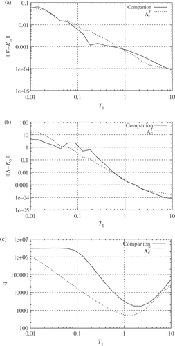
Given the inverse of J UU in (Equation36), it is clearly important that J UU is well conditioned to avoid numerical problems. As mentioned in § 2, the choice of generalised hold matrix A u does affect the conditioning of J UU ; from (Equation27), so does τ1. This point is examined further in § 4.
3.4 Quadratic programme
Lemma 3.1 Constrained optimisation
The minimisation of the cost function J ic of Equation (Equation27) subject to the constraints (Equation26) is equivalent to the solution of the QP:
Proof
See Chen and Gawthrop (Citation2006).□
4. Example
A unit double integrator has the transfer function and has a state-space representation of the form of (Equation1) where:
The controller was designed as in §§ 2 and 3 using Octave (Eaton Citation2002) and simulated using Scilab (Campbell, Chancelier, and Nikoukhah Citation2006). To test the numerical properties of the cost (Equation28) with respect to the time horizon τ1, three functions were evaluated:
-
the norm of the difference between the LQR gain k LQR (Equation10) and the derived gain
().
-
the norm of the difference between K computed from (Equation15) and from the cost function (Equation36) ().
-
the condition number η of J UU (Equation35) ().
Figure 1. Numerical properties. The three measures are plotted against optimisation horizon τ1 for two cases A
u
is the companion matrix with the same eigenvalues as A
c
and . (a) ‖k − k
LQR‖; (b) ‖k − k
LQR‖; (c) Condition number η.
Three different controllers were simulated:
-
the state-space controller with feedback gain (Equation41)
-
the corresponding unconstrained intermittent controller with a fixed intermittent interval Δ = 1 s
-
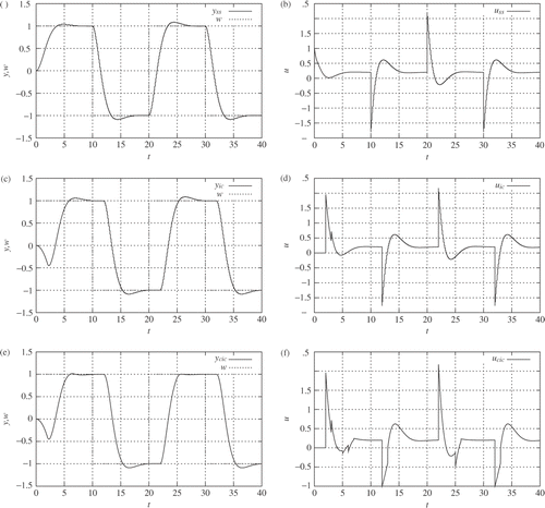
the corresponding constrained intermittent controller (CIC) with constraints y ≤ 1 at τ = 1 and u ≥ −1 at τ = 0.01.
-
The (unconstrained) intermittent and continuous controls differ initially due to the initial observer error caused by the constant offset disturbance. The intermittent control is worse because of the initial open-loop control generated with incorrect state information.
-
The disturbance is eliminated eventually because the controlled system contains an integrator.
-
The constrained intermittent control differs from the unconstrained intermittent control at the setpoint changes. At times t = 5 and 25 this is due to the constraint that y ≤ 1; at times t = 12.5 and 32.5 this is due to the constraint that u ≥ −1.
-
The constraint that y ≤ 1 is violated around time t = 5 due to the initial observer error; otherwise both constraints are satisfied.
5. Experimental verification
A series of experiments, based on the ‘Ball and Hoop’ (Wellstead Citation1979) apparatus, was conducted to verify the approach. Section 5.1 provides a mathematical model; § 5.2 discussed the controller implementation and § 5.3 describes the experimental results.
5.1 System modelling
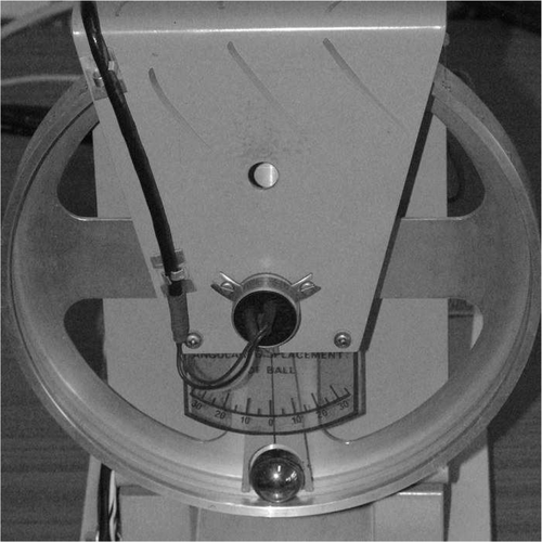
is a photograph of the ball and hoop laboratory experiment (Wellstead Citation1979) where a spherical ball bearing rolls without slipping within a metal hoop and the hoop rotates about its centre driven by a DC motor. The angle of an arbitrary point on the hoop from vertical is denoted by θ h and the angle subtended by the ball centre by θ b , the corresponding angular velocities are Ω h and Ω b , respectively. The hoop radius is r h . The hoop has a velocity feedback loop with setpoint Ω0 designed so that:
Assuming that the angle θ b is small, the translational velocity v b = r h Ω b of the ball along the hoop can be written in terms of the distance x b = r h θ b as:
The rotational motion of the ball is given in terms of its angular velocity ω b as:
Defining the relative velocities and
as
It is always difficult to include an accurate friction model in such systems; here, we have chosen to add a linear coulomb friction term to the right-hand side of (Equation48). With this addition, and substituting from the ordinary differential equation equivalent of (Equation42) finally gives:
Using Equation (Equation50) the state equations are of the form of (Equation1) where:
Numerical values appear in . The friction coefficient was estimated, the rest were taken from data sheets for the experiment. Without the friction coefficient, this system would have four poles at s = 0, and s = ±jω0 where
. The first two reflect the hoop dynamics and the last two reflect the ball dynamics. With the friction included, the ball exhibits lightly damped oscillations.
Table 1. System numerical values.
5.2 Control design and implementation
The purpose of this experiment is to control the hoop position without moving the ball excessively. One approach to this is to set up a linear-quadratic cost function with weighting on both hoop and ball position. However, this linear approach gives rise to ball motion proportional to hoop motion.
On the other hand, a fixed constraint on ball motion can be imposed using the CIC of this article. In particular, hoop angle θ h is to be controlled with a hard constraint on the ball angle θ b .
The controller was designed off-line as in §§ 2 and 3 using Octave (Eaton Citation2002). The controller was implemented on a computer with an Intel core 2 duo processor running at 1.4 GHz running the Ubuntu 7.1 32bit distribution with an RTAI kernel compiled from a standard Linux 2.6.23.14 kernel patched with RTAI-3.6. The controller was implemented using RTAI-lab (Bucher and Balemi Citation2006) which is in turn based on Scilab 4.2 (Campbell et al. Citation2006); in particular, the generalised hold was implemented using the Scilab ‘jump’ block. A special Scilab block was used to implement the QP using Hildreth's method Luenberger (Citation1984). Matlab code used previously by Gawthrop and Wang (Citation2007) was translated into C++ using the mat2cpp, BLAS and ATLAS libraries. This C++ code was then incorporated into the Scilab block using a C wrapper function.
5.3 Experimental results
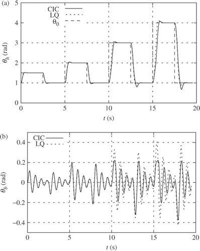
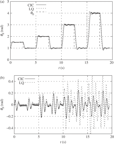
Two controllers were evaluated in separate experiments at a base sample interval of 2 ms. A conventional linear-quadratic state-feedback/observer with parameters from and the corresponding constrained intermittent control with the state constraint θ b ≤0.2 rad and intermittent interval 10 ms. For the purposes of comparison, a numerical simulation of the hoop with corresponding controller was run in real-time and in parallel with the control of the real system. To demonstrate the non-linear nature of the constrained control, the hoop was subject to a square-wave setpoint of increasing amplitude.
Table 2. Controller numerical values.
gives the simulation results and gives the corresponding experimental results. Each figure has two parts:
-
The hoop angle θ h resulting from the experiment corresponding to each controller CIC, and linear quadratic (LQ)) together with the setpoint θ0.
-
The ball angle θ b .
Both the simulation and experimental results are quite similar thus verifying the system modelling and controller implementation. As expected, the linear quadratic controller gives a ball angle motion which increases with hoop angle setpoint. In contrast, the CIC keeps the ball angle within the constraint except for two cases. For small setpoint changes, the LQ and CIC behave in the same way, but for larger angles, the constraint on ball angle implies a corresponding change in the hoop motion which is evident from the figures. As in the example of § 4, the integrator inherent in the system leads to zero steady-state error.
The two cases of constraint violation are due to amplifier saturation, and this was verified by including this saturation into the simulation.
6. Conclusion
The generalised hold reformulation of intermittent control, first given by Gawthrop and Wang (Citation2007), has been restated in a form that is more convenient for analysis and implementation. In particular, explicit compact equations suitable for prediction, constraint formulation and optimisation are given. A simulated example illustrates the approach which is verified using a real-time implementation to control a mechanical system.
The issue of stability in the constrained case is, as is well known (Mayne, Rawlings, Rao, and Scokaert Citation2000), tied to the issue of feasibility. In particular, feasibility is a key issue for mechanical systems which typically have poles on the imaginary axis and often have poles in the right-half complex plane. As discussed in this article, constraint handling is coupled to choice of basis function. This article uses a particular set of basis functions matched to the desired closed-loop system. This has the advantage of using a few basis functions and giving good off-constraint performance; however, it is not clear that this is the best choice for constraint handling in more complicated situations than treated in § 5.
For these reasons, future work will combine the matched basis functions with Laguerre functions in the form of Kautz functions which have been previously used in the context of system identification (Wahlberg and Makila Citation1996; Bokor and Schipp Citation1998). We believe that this will combine good off-constraint performance with accurate handling of complicated constraints and lead to a theory of how to design basis functions for feasibility.
The control-system properties of intermittent control have yet to be investigated. In the unconstrained case, the article of Goodwin and Salgado (Citation1994) and the book of Feuer and Goodwin (Citation1996) provide a possible way forward.
Acknowledgements
Peter Gawthrop is a Leverhulme Emeritus Research Fellow and gratefully acknowledges the support of the Leverhulme Trust. Some of the work reported here was accomplished whilst the first author was a Visiting Professor at RMIT University, Melbourne supported by the RMIT Professorial fund and the Royal Academy of Engineering grant ITG C7-292. The work reported here is related to EPSRC Grant EP/F069022/1 ‘Intermittent control of man and machine’.
References
- Bokor , J and Schipp , F . 1998 . Approximate Identification in Laguerre and Kautz Bases . Automatica , 34 : 463 – 468 .
- Bucher , R and Balemi , S . 2006 . Rapid Controller Prototyping with Matlab/Simulink and Linux . Control Engineering Practice , 14 : 185 – 192 .
- Cairano , SD , Bemporad , A , Kolmanovsky , IV and Hrovat , D . 2007 . Model Predictive Control of Magnetically Actuated Mass Spring Dampers for Automotive Applications . International Journal of Control , 80 : 1701 – 1716 .
- Campbell , S , Chancelier , JP and Nikoukhah , R . 2006 . Modeling and Simulation in Scilab/Scicos , Berlin : Springer .
- Chen , WH and Gawthrop , PJ . 2006 . Constrained Predictive Pole-placement Control with Linear Models . Automatica , 42 : 613 – 618 .
- Eaton , JW . 2002 . GNU Octave Manual , Bristol, , UK : Network Theory Limited .
- Feuer , A and Goodwin , G . 1996 . Sampling in Digital Signal Processing and Control , Berlin : Birkhauser .
- Gawthrop , PJ . 2002 . “ Physical Model-based Intermittent Predictive Control ” . In Proceedings of the 8th IEEE International Conference on Methods and Models in Automation and Robotics , Edited by: Kaczorek , T . 707 – 712 . Szczecin, Poland : IEEE Press .
- Gawthrop , PJ . 2004 . “ Intermittent Constrained Predictive Control of Mechanical Systems ” . In Proceedings of the 3rd IFAC Symposium on Mechatronic Systems Edited by: Petersen , IR . Manly, , Australia : IFAC, . on CD-ROM
- Gawthrop , PJ and Ronco , E . 2002 . Predictive Pole-placement Control with Linear Models . Automatica , 38 : 421 – 432 .
- Gawthrop , PJ and Wang , L . 2006 . Intermittent Predictive Control of an Inverted Pendulum . Control Engineering Practice , 14 : 1347 – 1356 .
- Gawthrop , PJ and Wang , L . 2007 . Intermittent Model Predictive Control . Proceedings of the Institution of Mechanical Engineers Part I: Journal of Systems and Control Engineering , 221 : 1007 – 1018 .
- Giorgetti , N , Bemporad , A , Tseng , HE and Hrovat , D . 2006 . Hybrid Model Predictive Control Application Towards Optimal Semi-active Suspension . International Journal of Control , 79 : 521 – 533 .
- Goodwin , G , Graebe , S and Salgado , M . 2001 . Control System Design , Englewood Cliffs, NJ : Prentice-Hall .
- Goodwin , GC and Salgado , M . 1994 . Frequency Domain Sensitivity Functions for Continuous Time Systems Under Sampled Data Control . Automatica , 30 : 1263 – 1270 .
- Jacobs , OLR . 1974 . Introduction to Control Theory , Oxford, , UK : Oxford University Press .
- Kailath , T . 1980 . Linear Systems , Englewood Cliffs : Prentice-Hall .
- Kwakernaak , H and Sivan , R . 1972 . Linear Optimal Control Systems , New York : Wiley .
- Loram , ID , Gawthrop , P and Lakie , M . 2006 . The Frequency of Human, Manual Adjustments in Balancing an Inverted Pendulum is Constrained by Intrinsic Physiological Factors . The Journal of Physiology (Lond) , 577 : 403 – 416 .
- Luenberger , DG . 1984 . Linear and Nonlinear Programming , 2nd , New York : John Wiley and Sons .
- Maciejowski , J . 2002 . Predictive Control with Constraints , Englewood Cliffs, NJ : Prentice Hall .
- Mayne , D , Rawlings , J , Rao , C and Scokaert , P . 2000 . Constrained Model Predictive Control: Stability and Optimality . Automatica , 36 : 789 – 814 .
- Nair , GN and Evans , RJ . 2003 . Exponential Stabilisability of Finite-dimensional Linear Systems with Limited Data Rates . Automatica , 39 : 585 – 593 .
- Polderman , JW and Willems , JC . 1997 . Introduction to Mathematical System Theory: A Behavioral Approach , No. 26 in: Texts in Applied Mathematics Vol. 26 , Berlin : Springer .
- Rawlings , JB and Muske , KR . 1993 . The Stability of Constrained Receding Horizon Control . IEEE Transactions on Automatic Control , 38 : 1512 – 1516 .
- Ronco , E , Arsan , T and Gawthrop , PJ . 1999 . Open-loop Intermittent Feedback Control: Practical Continuous-time GPC . IEE Proceedings Part D: Control Theory and Applications , 146 : 426 – 434 .
- Wahlberg , B and Makila , PM . 1996 . On Approximation of Stable Linear Dynamical Systems using Laguerre and Kautz Functions . Automatica , 32 : 693 – 708 .
- Wang , L . 2001 . Continuous Time Model Predictive Control Using Orthonormal Functions . International Journal of Control , 74 : 1588 – 1600 .
- Wellstead , PE . 1979 . Introduction to Physical System Modelling , London, , UK : Academic Press .
