
ABSTRACT
Although heat-assisted plasma treatment enables drastic improvement of the adhesion property of polytetrafluoroethylene (PTFE), plasma-treated PTFE does not strongly adhere to any adherend. To clarify which rubber compounding agents positively affect the adhesion strength of a plasma-treated PTFE/rubber assembly, six types of unvulcanised rubbers were prepared and thermally compressed to a plasma-treated PTFE sheet. Thus, it was found that SiO2 addition to rubber drastically increased the adhesion strength of a plasma-treated PTFE/rubber assembly and cohesion failure of rubber occurred with large fractions of SiO2 although no adhesives were used. To confirm the reaction between plasma-treated PTFE and SiO2 powder, X-ray photoelectron spectroscopy (XPS) measurements were performed for the thermally compressed SiO2/PTFE assembly after repeated washing. The XPS results indicated that hydrophilic SiO2 powder strongly adhered to the plasma-treated PTFE, whereas hydrophobic SiO2 powder did not adhere to the PTFE. In this paper, a model was proposed for a possible mechanism of strong adhesion of a PTFE/rubber assembly through both hydrogen and covalent bonds between silanol groups of the SiO2 powder surface in the rubber and hydroxyl or carboxyl groups on the plasma-treated PTFE.
Introduction
Rubber has elasticity but poor chemical resistance and sliding properties. In contrast, polytetrafluoroethylene (PTFE), which is a fluoropolymer, has high chemical resistance and good sliding properties but no elasticity. Combining rubber and PTFE can compensate for the disadvantages of both materials. However, PTFE does not easily adhere to other types of materials. PTFE not only has an extremely low surface energy, in common with fluoropolymers, but also has a weak boundary layer (WBL).[Citation1,Citation2] Therefore, it is essential not only to generate oxygen-containing radicals and functional groups on PTFE surfaces but also to remove and/or recover the WBL of PTFE surface to improve its adhesion property. To generate oxygen-containing radicals and functional groups and remove and/or recover the WBL, corrosive solutions such as sodium–naphthalene and sodium–ammonium complex solutions have been used as conventional methods.[Citation3,Citation4] As a result, the adhesion properties of PTFE drastically improved. However, corrosive solutions have significant disadvantages: a negative impact on humans and the environment, strong odours, and sodium residues on PTFE. An alternative method that does not require the corrosive solutions has, therefore, long been needed. Although many researchers attempted to develop an alternative method via surface treatments involving dry processes such as ion and plasma irradiation, the realisation of good adhesion properties of PTFE (over 1 N/mm) has been difficult.[Citation5–Citation9] Therefore, several combinations of surface treatments such as plasma irradiation and surface graft polymerisation were developed.[Citation4,Citation10–Citation12] In addition, in recent years, good adhesion properties of PTFE were realised without graft polymerisation under special conditions of ion or plasma irradiation by Yumoto’s[Citation13] and Ohkubo’s groups.[Citation14,Citation15] Yumoto’s group reported that the adhesion strength between ion-irradiated PTFE and polypropylene tape containing glass fibre through an epoxy adhesive drastically increased to 1.5 N/mm upon N2 ion irradiation under a high acceleration voltage. Ohkubo’s group reported that the adhesion strength between plasma-treated PTFE and isobutylene–isoprene rubber (IIR) drastically increased to over 2.0 N/mm upon helium (He) heat-assisted plasma treatment at above 200°C. In the report, cohesion failure of IIR occurred in the middle of T-peel test despite the absence of adhesives and graft polymerisation agents. Although Ohkubo et al. studied a modified PTFE surface in detail by electron spin resonance (ESR) measurement, X-ray photoelectron spectroscopy (XPS), scanning electron microscopy, atomic force microscopy, nanoindentation, and contact angle measurement and achieved extremely strong adhesion between the plasma-treated PTFE and other materials, the rubber surface was barely studied. Thus, the mechanism of strong adhesion is unclear. Although there are several reports on improved adhesion strength between rubber and metal without using adhesives[Citation16–Citation19], there are few reports on the improvement of the adhesion strength between rubber and plasma-treated fluoropolymers. In this study, we prepared six types of rubbers to clarify which components in rubber affect the adhesion strength of a plasma-treated PTFE/rubber assembly. In addition, a direct adhesion test of the rubber compounding agent, which induces strong adhesion, with the plasma-treated PTFE was performed.
Experimental
Materials
Commercially available PTFE sheet (NITOFLON®No.900UL, Nitto Denko: Osaka, Osaka, Japan, thickness: 0.2 mm) was cut into 35 mm × 70 mm pieces, which were used as fluoropolymer specimens. Six types of unvulcanised rubbers were mixed and prepared using the materials shown in –. Sulphur-free chloroprene rubber (CR, M-40, Denka: Chuo-ku, Tokyo, Japan) and natural rubber (NR, Ribbed Smoked Sheet No. 1, Rubber source: Indonesia) were used as the main rubber components. Cellulose powder (CF11, Whatman: Kent, UK) and hydrophilic SiO2 powder (Nipsil VN3, wet process, Tosoh Silica: Minato-ku, Tokyo, Japan) were used as reinforcing materials. To compare the differences between manufacturing methods, wet and dry processes, hydrophilic SiO2 powder (HDK®N20, dry process, Wacker Chemie AG: München, Germany), and hydrophobic SiO2 powder covered with polydimethylsiloxane (HDK®H18, dry process, Wacker Chemie AG) were also used as reinforcing agents. Dicumyl peroxide (Percumyl®D, NOF: Shibuya-ku, Tokyo, Japan), fine sulphur powder (325 Mesh, Hosoi Chemical Industry: Chuo-ku, Tokyo, Japan), and 2-dibutylamino-4,6-dimercapto-s-triazine (Zisnet DB, Sankyo Chemical: Osaka, Osaka, Japan) were used as crosslinking agents. Zinc oxide (JIS Grade No.2, Hakusui Tech: Osaka, Osaka, Japan) and stearic acid (C16:22%–32%, Stearic Acid 50S, New Japan Chemical: Osaka, Osaka, Japan) were used as vulcanisation accelerator aids. N-(tert-butyl)-2-benzothiazolesulfenamide (Nocceler NS-P, Ouchi Shinko Chemical Industrial: Chuo-ku, Tokyo, Japan) was used as a vulcanisation accelerator. N-phenyl-1-naphthylamine (Nocrac PA, Ouchi Shinko Chemical Industrial) was used as an antioxidant for rubber. Sample 1 containing CR was prepared to confirm the effect of chloride on adhesion strength. Note that it was assumed that the chlorides would react with peroxide radicals and/or oxygen-containing functional groups on the heat-assisted plasma-treated PTFE. Sample 2 containing NR and dicumyl peroxide was prepared to confirm the effect of a peroxide crosslinking agent on adhesion strength. The dicumyl peroxide induces the generation of carbon radicals in NR by changing double bonds to single bonds. It was assumed that the carbon radicals would react with peroxide radicals and/or oxygen-containing functional groups on the heat-assisted plasma-treated PTFE. Sample 3 containing NR and sulphur was prepared to confirm the effect of a sulphur crosslinking agent on adhesion strength. It was assumed that sulphur would react with peroxide radicals and/or oxygen-containing functional groups on the heat-assisted plasma-treated PTFE. Sample 4 containing NR, sulphur, and triazine thiol was prepared to confirm the effect of a thiol crosslinking agent on adhesion strength. It was assumed that the triazine thiols would react with peroxide radicals and/or oxygen-containing functional groups on the heat-assisted plasma-treated PTFE. Sample 5 containing NR, sulphur, and SiO2 powder was prepared to confirm the effect of SiO2 powder on adhesion strength. It was assumed that the SiO2 powder would react with peroxide radicals and/or oxygen-containing functional groups on the heat-assisted plasma-treated PTFE. Sample 6 containing NR, sulphur, triazine thiol, and SiO2 powder was prepared to confirm the effect of both triazine thiol and SiO2 powder on adhesion strength.
Table 1. Components of sample 1.
Table 2. Components of sample 2.
Table 3. Components of sample 3.
Table 4. Components of sample 4.
Table 5. Components of sample 5.
Table 6. Components of sample 6.
Method
Plasma treatment
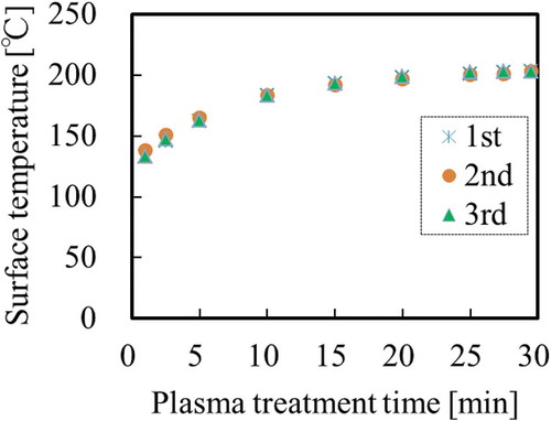
Prior to use, PTFE sheets were sequentially washed with acetone (99.5%, Kishida Chemical: Osaka, Osaka, Japan) and pure water for 1 min each using an ultrasonic bath (USK-1R, AS-ONE: Osaka, Osaka, Japan). The washed PTFE sheets were then dried using an air gun containing N2 gas (99.99%, Iwatani Fine Gas: Amagasaki, Hyogo, Japan). The dried PTFE sheets were then fixed on a cylindrical rotation stage (L = 34 mm, Φ= 40 mm).[Citation15] The stage containing PTFE sample was placed in a custom-made chamber (Meisyo Kiko: Tanba, Hyogo, Japan) with the vacuum system.[Citation20] The reactor pressure was decreased to below 10 Pa using a rotary pump (GDH-361, Shimadzu: Kyoto, Kyoto, Japan) then helium gas (He, 99.99%, Iwatani Fine Gas) was introduced until the atmospheric pressure (101300 Pa). Plasma was generated between two electrodes using a 13.56 MHz radio frequency (RF) generator in the camber filled with He gas without flowing. All the PTFE sheets were heat-assisted plasma-treated for 600 s at 18.7 W/cm2. The surface temperature of the PTFE samples during plasma treatment was measured with a digital radiation thermometer system (FT-H40K and FT-50A, Keyence: Osaka, Osaka, Japan). shows the representative temperature profiles of PTFE surface three times. It was confirmed that all the maximum surface temperatures were above 200°C. All the error of temperature profiles three times were within 5°C, which indicates high reproducibility. Effect of surface temperature on adhesion strength of PTFE were previously studied and reported.[Citation14,Citation15] When surface temperature of PTFE during plasma treatment was lower than 100°C, the adhesion strength of plasma-treated PTFE/IIR was below 0.2 N/mm. In contrast, when surface temperature of PTFE during plasma treatment was higher than 200°C, the adhesion strength of plasma-treated PTFE/IIR was above 2.0 N/mm and cohesion failure of IIR occurred. According to these reports, plasma condition (for 600 s at 18.7 W/cm2) in this study was chosen to be at higher than 200°C.
Figure 1. Representative temperature profiles of PTFE surface during heat-assisted plasma treatment for 600 s at 18.7 W/cm2 three times.
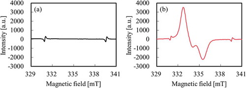
Prior to adhesion strength test, confirmation of surface chemical composition using a Quantum 2000 instrument (Ulvac-Phi: Chigasaki, Kanagawa, Japan), confirmation of generation of peroxide radicals (C–O–O•) using a JES-FA100x (JEOL: Akishima, Tokyo, Japan), and adhesion confirmation test of heat-assisted plasma-treated PTFE for 600 s at 18.7 W/cm2 were performed. Although only the peak attributed to CF2 was observed at ca. 292 eV for as-received PTFE in , the intensity of the peak attributed to fluorine-containing functional groups (CF3, CF2, C–F) decreased and the intensities of the peaks attributed to oxygen-containing functional groups (O–C=O, C=O, C–O) and carbon groups (C–C, C=C) increased in as compared to those of the as-received PTFE upon heat-assisted plasma treatment. Although only the peaks attributed to Mn2+ markers were observed at ca. 331 and 340 mT for as-received PTFE in , the peak attributed to alkyl-type peroxide radicals (–CF2CFOO•CF2–) was detected upon heat-assisted plasma treatment in . These behavior in this study were consistent with those in previous reports.[Citation14,Citation15] It is previously reported that oxygen-containing functional groups and peroxy radicals generate when fluoropolymers plasma-treated using noble gas is exposed to the air.[Citation21] In addition, the plasma-treated PTFE/IIR was also above 2.0 N/mm and cohesion failure of IIR also occurred. As a result, it was confirmed that this plasma condition had no problems. Plasma treatment was performed only on the PTFE surface and not on the unvulcanised rubber surface.
Figure 2. Representative C1s-XPS spectra of PTFE samples (a) before and (b) after heat-assisted plasma treatment for 600 s at 18.7 W/cm2.
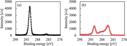
Figure 3. Representative ESR spectra of PTFE samples (a) before and (b) after heat-assisted plasma treatment for 600 s at 18.7 W/cm2.
Adhesion strength test
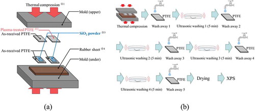
shows a schematic diagram of the general sequence for the adhesion test. First, the plasma-treated PTFE samples were placed on unvulcanised rubber sheets in a mould. Second, the assembly samples were compressed at appropriate temperatures and times for each type of unvulcanised rubber because of complete crosslinking occurring when using a hot-pressing machine (AH-2003, AS-ONE). Each vulcanisation time was confirmed via a vulcanisation judgement test using a rubber testing machine (Curelastometer type V, Orientec: Toyoshima-ku, Tokyo, Japan), as shown in . Here no adhesives were used in the adhesion process. Third, the rubber/PTFE assembly was returned to room temperature. Fourth, the adhesion strengths of the rubber/PTFE assembly was measured with a T-peel test using a universal testing device (AG-1000D, Shimadzu) and/or combination of a digital force gauge (ZP-200N, Imada; Toyohashi, Aichi, Japan) and an electric-driven stand (MX-500N, Imada). Finally, the adhesion strengths were calculated by dividing the average tensile strength by the width of the rubber/PTFE assembly (ca. 10 mm). Three samples were prepared under the same conditions to confirm the reproducibility.
Figure 4. Schematic diagram of the sample preparation sequence for the adhesion test.
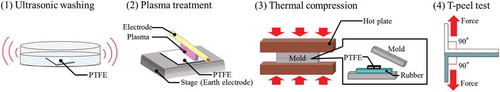
Figure 5. Results of the vulcanisation judgement test for confirmation of proper vulcanisation time. (a) Sample 1 at 180°C, (b) sample 2 at 170°C, (c) Sample 3 at 160°C, (d) Sample 4 at 150°C, (e) Sample 5 at 180°C, and (f) Sample 6 at 160°C.
Surface chemical composition analysis
XPS measurements were conducted with a scanning XPS microprobe (PHI5000VersaProbeII, Ulvac-Phi) attached to a monochromated Al-Kα source. The XPS spectra were obtained at a take-off angle of 45°. The area of X-ray irradiation was Φ = 100 μm, the pass energy was 11.75 eV, and the step size was 0.05 eV. C1s-XPS and Si2p-XPS spectra were collected from 280 to 296 eV and from 95 to 110 eV, respectively. The cumulative number of the measurements was five. During a XPS measurement, the low-speed electron beam and an Ar ion beam were used to irradiate the measured samples to neutralise their charges.
Results and discussion
Adhesion strength between plasma-treated PTFE and rubber
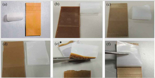
shows the adhesion strength between plasma-treated PTFE and rubber Samples 1–6. shows the photographs of Samples 1–6 after the T-peel test. For Sample 1, the adhesion strength was 0.14 N/mm and the rubber was easily peeled (). This indicates that chlorides do not interact with peroxide radicals and/or oxygen-containing functional groups on heat-assisted plasma-treated PTFE. For Sample 2, the adhesion strength was 0.10 N/mm and the rubber was easily peeled (). This indicates that carbon radicals do not interact with peroxide radicals and/or oxygen-containing functional groups on heat-assisted plasma-treated PTFE. For Sample 3, the adhesion strength was 0.07 N/mm and the rubber was easily peeled (). This indicates that the sulphur does not interact with peroxide radicals and/or oxygen-containing functional groups on the heat-assisted plasma-treated PTFE. For Sample 4, the adhesion strength was 0.03 N/mm and the rubber was also easily peeled (). This indicates that triazine thiols do not interact with peroxide radicals and/or oxygen-containing functional groups on heat-assisted plasma-treated PTFE. For Sample 5, the adhesion strength was 1.86 N/mm and cohesion failure of rubber occurred (). This indicates that SiO2 powder interacts with peroxide radicals and/or oxygen-containing functional groups on heat-assisted plasma-treated PTFE. For Sample 6, the adhesion strength was 1.67 N/mm and the rubber was difficult to peel but cohesion failure of rubber did not occur (). The adhesion strength of Sample 6 (1.67 N/mm) was much higher than that of Sample 4 (0.04 N/mm) but slightly lower than that of Sample 5 (1.86 N/mm). These results indicate that the SiO2 powders positively affect the adhesion strength, but the triazine thiols negatively affect the adhesion strength.
Figure 6. Adhesion strength between the heat-assisted plasma-treated PTFE and rubber for samples 1–6 prepared as shown in –. no adhesives were used. * indicates that cohesion failure of rubber occurred in the middle of a T-peel test.
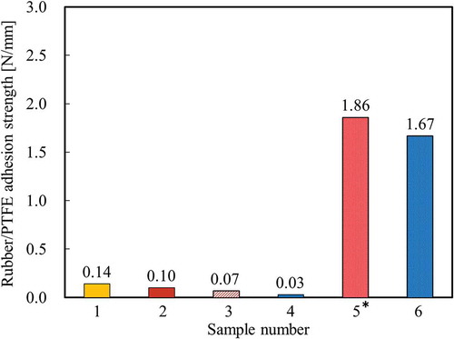
Figure 7. Photographs of samples 1–6 after T-peel test. (a) sample 1, (b) sample 2, (c) sample 3, (d) sample 4, (e) sample 5, and (f) sample 6. * indicates that cohesion failure of rubber occurred in the middle of a T-peel test.
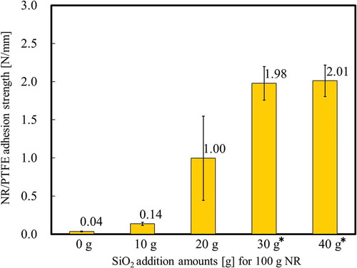
To confirm the additive effect of SiO2 powder on the adhesion strength, NR samples were prepared with different amounts of added SiO2 in the range 0–40 g to 100 g NR. This component is shown in . Except for SiO2, other components and their amounts for are the same as in Sample 5 (). shows the adhesion strength between the heat-assisted plasma-treated PTFE and NR samples prepared with different amounts of SiO2. The adhesion strength increased with increasing the amount of SiO2 and cohesion failure of NR occurred when 30 and 40 g SiO2 were added. It is confirmed that the addition of SiO2 powder to NR affected the adhesion strength.
Table 7. Components of NR with different amounts of SiO2.
Figure 8. Adhesion strength between the heat-assisted plasma-treated PTFE and NR samples prepared with different amounts of SiO2 as shown in . * indicates that cohesion failure of rubber occurred in the middle of a T-peel test.
Confirmation of reaction between plasma-treated PTFE and SiO2 powder using XPS
To confirm the reaction between plasma-treated PTFE and SiO2 powder, a direct reaction was observed in the absence of all the NR components except for SiO2 powder. First, SiO2 powder was directly thermally compressed to heat-assisted plasma-treated PTFE sheet at almost 10 MPa at 180°C for 10 min using a compression moulding machine (NF-50, Shinto Metal Industries), as shown in . Second, the unreacted SiO2 powder on the plasma-treated PTFE was removed by washing with tap water for ca. 20 s and with distilled water for ca. 10 s, followed by ultrasonic washing in distilled water for 5 min; each wash was repeated more than four times (). Finally, XPS measurements were conducted. Prior to the XPS measurements, all the samples were dried using an air gun. For comparison, a reference sample was prepared using as-received PTFE via the process shown in .
Figure 9. Schematic diagram of the sequence for confirming the reaction between plasma-treated PTFE and SiO2 powder using XPS. (a) before thermal compression, (b) after thermal compression. *1 Thermal compression was performed at almost 10 MPa at 180°C for 10 min. *2 Heat-assisted plasma treatment was performed for 600 s at 18.7 W/cm2. *3 Three types of SiO2 powders: VN3, H18, and N20 were used. *4 A vulcanised rubber having high heat-resistance was used as a cushion.
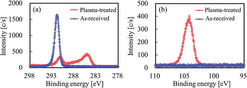
shows the XPS spectra of the PTFE surface after thermal compression with SiO2 powder (VN3). Although only the peak attributed to CF2 was observed at ca. 292 eV for as-received PTFE, the intensity of the peak attributed to fluorine-containing functional groups (CF3, CF2, C–F) decreased and the intensities of the peaks attributed to oxygen-containing functional groups (O–C=O, C=O, C–O) and main carbon groups (C–C, C–H, C=C) increased as compared to those of the as-received PTFE upon heat-assisted plasma treatment, as shown in the C1s-XPS spectra (). As a result, surface modification of PTFE via heat-assisted plasma treatment was confirmed. Si was detected on the plasma-treated PTFE but not the as-received PTFE by Si2p-XPS spectrum (). These results indicated that SiO2 powder remained on the plasma-treated PTFE surface despite repeated washing. In addition, the strong adhesion of SiO2 powder implied that this chemically reacted with the plasma-treated PTFE surface.
Figure 10. XPS spectra of the PTFE surface after thermal-compression with hydrophilic SiO2 powder (VN3) (a) C1s, (b) Si2p.
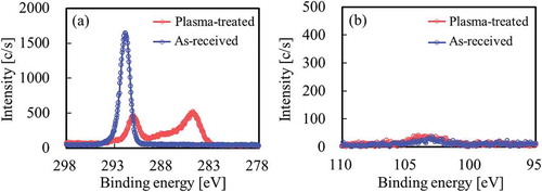
To compare the effect of wettability of SiO2 surface on adhesion to PTFE, hydrophobic SiO2 powder (H18), which was prepared through a dry process, was used for the same confirmation test. shows the XPS spectra of the PTFE surface after thermal compression with hydrophobic SiO2 powder (H18). as well as indicates surface modification of PTFE via heat-assisted plasma treatment. In contrast, Si was barely detected in either the as-received or the plasma-treated PTFE via Si2p-XPS spectra (). These results indicated that hydrophobic SiO2 powder barely remained on the plasma-treated PTFE surface as there was no interaction between both materials.
Figure 11. XPS spectra of the PTFE surface after thermal-compression with hydrophobic SiO2 powder (H18) (a) C1s, (b) Si2p.
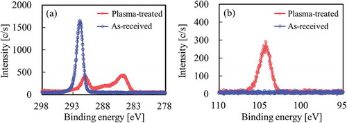
VN3 is a hydrophilic SiO2 powder prepared through a wet process, whereas H18 is a hydrophobic SiO2 powder prepared through a dry process. Taking the manufacturing method of SiO2 powder into account, hydrophilic SiO2 powder (N20), which was prepared through a dry process, was used for the same confirmation test. shows the XPS spectra of the PTFE surface after thermal compression with hydrophilic SiO2 powder (N20). as well as and indicates surface modification of PTFE via heat-assisted plasma treatment. Si was detected in the plasma-treated PTFE but not the as-received PTFE via the Si2p-XPS spectra in as well as .
Figure 12. XPS spectra of the PTFE surface after thermal-compression with hydrophilic SiO2 powder (N20) (a) C1s, (b) Si2p.
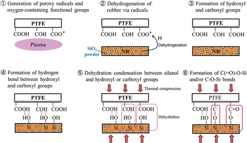
The atomic ratios of the PTFE surface after thermal compression with SiO2 powder were calculated from the survey XPS spectra, as shown in . For all as-received PTFE, the Si atomic ratios were lower than 1%. In contrast, for plasma-treated PTFE except addition of hydrophobic SiO2 (H18), the Si atomic ratios were higher than 4.5%. Although two types of hydrophilic SiO2 powder (VN3 and N20) strongly adhered to the plasma-treated PTFE surface, hydrophobic SiO2 powder (H18) did not adhere. The difference indicates that silanol groups (Si–OH) of the SiO2 surface affect the adhesion strength between the plasma-treated PTFE and rubber. A proposed model for strong adhesion is shown in . First, peroxy radicals and oxygen-containing functional groups (C(=O)–OH, C–OH) are generated upon plasma treatment. Second, peroxy radicals on the plasma-treated PTFE may induce the dehydrogenation of rubber. Third, hydroxyl and carboxyl groups are generated regardless of the presence or absence of the second step: dehydrogenation of rubber. Fourth, hydrogen bonds are formed between hydroxyl and carboxyl groups on the PTFE surface and silanol groups of the SiO2 powder on the rubber surface. Fifth, dehydration condensation occurs between silanol and hydroxyl or carboxyl groups. Finally, C–O–Si and/or C(=O)–O–Si bonds are formed. Considering that NR cohesion failure occurred when SiO2 powder was added, it is reasonable to suppose that covalent bonds as well as hydrogen bonds are formed.
Table 8. Atomic ratios of the PTFE surface after thermal compression with SiO2 powder, which calculated from each survey XPS spectrum.
Figure 13. Proposed model for strong adhesion between heat-assisted plasma-treated PTFE and rubber containing SiO2 powder.
Conclusion
We prepared six types of rubbers to clarify the effects of rubber compounding agent on adhesion strength between rubber and heat-assisted plasma-treated PTFE. It was found that addition of SiO2 powder to rubber was particularly effective for improving the adhesion strength. The adhesion strength increased with increasing the amount of SiO2, and the cohesion failure of rubber occurred when the amount of SiO2 was more than 30 g to 100 g NR. In addition, it was confirmed that hydrophilic SiO2 powder strongly adhered to the heat-assisted plasma-treated PTFE surface. We proposed a model of high adhesion strength upon addition of SiO2 powder. This simple method of adding SiO2 powder could be applied not only to rubber but also to various polymers to improve their adhesion to heat-assisted plasma-treated fluoropolymers.
Acknowledgments
The study was supported by a grant from the Japan Society for the Promotion of Science (JSPS KAKENHI Grant Number 15K05723).
Additional information
Funding
References
- Schonhorn, H.; Hansen, R. H. J. Appl. Polym. Sci. 1967, 11, 1461–1474.
- Bikerman, J. J.;. Ind. Eng. Chem. 1967, 59, 40–44.
- Marchesi, J. T.; Keith, H. D.; Garton, A. J. Adhesion. 1992, 39, 185–205.
- Okubo, M.; Tahara, M.; Aburatani, Y.; Kuroki, T.; Hibino, T. IEEE Trans. Ind. Appl. 2010, 46, 1715–1721.
- Inagaki, N.; Tasaka, S.; Umehara. J. Appl. Polym. Sci. 1999, 71, 2191–2200.
- Kim, S. R.;. J. Appl. Polym. Sci. 2000, 77, 1913–1920.
- Seo, Y.; Kim, S.; Kim, H.; Kim, J. Langmuir. 2005, 21, 3432–3435.
- Rodriguez-Santiago, V.; Bujanda, A. A.; Stein, B. E.; Pappas, D. D. Plasma Process. Polym. 2011, 8, 631–639.
- Watanabe, T.; Iwao, T.; Yumoto, M. IEEJ Trans. Fund. Mater. 2012, 132, 245–250.
- Kang, E. T.; Zhang, Y. Adv. Mater. 2000, 12, 139–150.
- Zhang, M. C.; Kang, E. T.; Neoh, K. G.; Tan, K. L. Colloid. Surf. A. 2001, 176, 139–150.
- Zhang, L.; Chen, Y.; Dong, T. Surf. Interface Anal. 2004, 36, 311–316.
- Takata, R.; Nagasaka, Y.; Li, Q.; Iwao, T.; Yumoto, M. IEEJ Trans. Fund. Mater. 2015, 135, 41–46.
- Ohkubo, Y.; Ishihara, K.; Sato, H.; Shibahara, M.; Nagatani, A.; Honda, K.; Endo, K.; Yamamura, K. RSC Adv. 2017, 7, 6432–6438.
- Ohkubo, Y.; Ishihara, K.; Shibahara, M.; Nagatani, A.; Honda, K.; Endo, K.; Yamamura, K. Sci. Rep. 2017, 7, 9476.
- Tsai, Y. M.; Boerio, F. J.; Kim, D. K. J. Adhesion. 1997, 61, 247–270.
- Cho, P. L.; Jeon, G. S.; Ryu, S. K.; Seo, G. J. Adhesion. 1999, 70, 241–258.
- Jeon, G. S.; Han, M. H.; Seo, G. J. Adhesion Sci. Technol. 1999, 13, 153–168.
- Jayaseelan, S. K.; Van Ooij, W. J. J. Adhesion Sci. Technol. 2001, 15, 967–991.
- Yamamoto, Y.; Akiyama, H.; Ooka, K.; Yamamura, K.; Oshikane, Y.; Zettsu, N. Curr. Appl. Phys. 2012, 12, S63–S68.
- Momose, Y.; Tamura, Y.; Ogino, M.; Okazaki, S.; Hirayama, M. J. Vac Sci. Technol. A. 1992, 10, 229–238.