
ABSTRACT
During the second phase of the Alpine Fault, Deep Fault Drilling Project (DFDP) in the Whataroa River, South Westland, New Zealand, bedrock was encountered in the DFDP-2B borehole from 238.5–893.2 m Measured Depth (MD). Continuous sampling and meso- to microscale characterisation of whole rock cuttings established that, in sequence, the borehole sampled amphibolite facies, Torlesse Composite Terrane-derived schists, protomylonites and mylonites, terminating 200–400 m above an Alpine Fault Principal Slip Zone (PSZ) with a maximum dip of 62°. The most diagnostic structural features of increasing PSZ proximity were the occurrence of shear bands and reduction in mean quartz grain sizes. A change in composition to greater mica:quartz + feldspar, most markedly below c. 700 m MD, is inferred to result from either heterogeneous sampling or a change in lithology related to alteration. Major oxide variations suggest the fault-proximal Alpine Fault alteration zone, as previously defined in DFDP-1 core, was not sampled.
Introduction
The Alpine Fault, Deep Fault Drilling Project (DFDP)
The Alpine Fault, Deep Fault Drilling Project (DFDP; Townend et al. Citation2009) aims to drill into New Zealand’s Alpine Fault Zone at a range of depths along an exhumation trajectory. At the drill sites, in the Whataroa and Waitangi-taona River areas (), this seismically active structure (Sutherland et al. Citation2007) accommodates around 70% of the 37 mm/yr of obliquely convergent relative Pacific-Australian Plate motions by dextral-reverse shear (Norris & Cooper Citation2001; DeMets et al. Citation2010). Uplift of the Pacific Plate hanging wall at rates of 6–9 mm/yr (Little et al. Citation2005; Beavan et al. Citation2010) coupled with rapid erosion in response to abundant orographic rainfall results in exposure of dominantly Mesozoic metasedimentary and metavolcanic rocks that have a polyphase metamorphic fabric that was subject to peak pressures and temperatures in the oligoclase zone of the amphibolite facies (Vry et al. Citation2004; Beyssac et al. Citation2016). Although complex in detail, the structural and metamorphic fabrics, as well as the kinematic history of these rocks, is simpler than that of any other similar structure worldwide (Townend et al. Citation2009), so study of the fault rocks promises a globally unique opportunity to determine how they progressively evolved.
Figure 1. A, Overall tectonic setting and location map. Seafloor topography after Smith and Sandwell (Citation1997). B, Location of DFDP boreholes within the central Alpine Fault Zone (AFZ). This is an enlargement of the orange box in A. C, Summary of the expected geological sequence in the Alpine Fault Zone hanging wall. Typical Alpine Fault Zone outcrops can be observed at Harold, Stony and Hare Mare Creeks and the Waikukupa River, modified from Norris and Cooper (Citation2007). Coordinate system is NZ Transverse Mercator, NZGD2010.
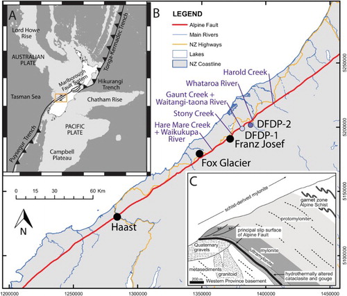
A first phase of drilling, DFDP-1, undertaken in 2011 at Gaunt Creek, a tributary to the Waitangi-taona River, successfully sampled smectite-rich gouges inferred to be active or recently active Principal Slip Zones (PSZ) in two boreholes at depths of 90.75 m in DFDP-1A and 128.10 m and 143.85 m in DFDP-1B. Observations during and after drilling allowed description of fault zone architecture appropriate for the <100 m thickness of fault rocks drilled immediately around the PSZs (Sutherland et al. Citation2012), measurement and correlation of petrophysical properties (Townend et al. Citation2013) and definition of a characteristic suite of lithologies (Toy et al. Citation2015).
The second phase of drilling, DFDP-2 (Sutherland et al. Citation2017), was carried out from August 2014–January 2015 in the Whataroa Valley ( and , see also reference frames and corrections section of the supplementary data to this contribution). Two boreholes were drilled: DFDP-2A penetrated to 212.6 m MD (where MD, Measured Depth, is the length of drill string from the top of the drill rig table, at an elevation of 98.14 m, to the bit) and DFDP-2B penetrated to 893.1 m MD. Three main types of samples were recovered from DFDP-2A during the preliminary stages of drilling (). Due to a greater than anticipated thickness of Quaternary sediments encountered in this borehole (Sutherland et al. Citation2015), a second borehole (DFDP-2B) was spudded nearby. The aim to penetrate the active PSZ of the fault at a depth of approximately 1 km, was not realised in either hole due to scientific and technical difficulties further explained by Sutherland et al. (Citation2015). Nevertheless, a substantial set of samples, continuous measurements, and wireline geophysical logs were collected, and an optical fibre cable was installed that provides longer term monitoring capability (Sutherland et al. Citation2015, Citation2017).
Table 1. Summary of samples collected from DFDP-2A.
DFDP-2 was initially drilled as an open hole through the basement rocks, using a polycrystalline diamond composite (PDC) bit (but other types of drillbits were sometimes used at depths <547 m, as further explained in the supplementary data). This generated small (millimetre-sized) chips of rock known as ‘cuttings’. The technical plan was to change drilling methods to recover intact rock cores at a distance of up to 300 m above the PSZ. The sub-surface structure at the drillsite could not be unequivocally defined from geophysical surveys or by projection of surface structure to depth, so additional interpretation of proximity to the PSZ was based on observations of the cuttings and correlation to lithological definitions based on past outcrop mapping (e.g. Little et al. Citation2002; Toy et al. Citation2012b) and from DFDP-1 (Toy et al. Citation2015). The sequence was expected to be lithologically part of the Aspiring Lithologic Association, a sub-division of the Torlesse Composite Terrane—i.e. quartzofeldspathic metasediments (pelite and psammite) with minor metabasite (amphibolite) and metachert, typically in metre to decimetre thick layers (Craw Citation1984; Cox & Barrell Citation2007). The maximum metamorphic grade was expected to be the K-feldspar zone of the amphibolite facies (Cox & Barrell Citation2007). Close to the Alpine Fault PSZ we anticipated mylonite or cataclasite-series rocks comparable to one of the eight lithological units observed in DFDP-1 boreholes (; cf. Toy et al. Citation2015), but first we expected to encounter lower shear strain equivalents such as mylonites, protomylonites and the non-mylonitic precursors to these mylonitic rocks, the Alpine Schists (Norris & Cooper Citation2007; Toy et al. Citation2008). Hand samples are commonly categorised as one or other of these tectonites, based on foliation characteristics at mm to cm-scale, as well as the presence of cm-spaced shear bands and the preservation of cm-scale fold hinges, as explained by Toy et al. (Citation2012b).
Table 2. Characteristic Alpine Fault lithologies defined by Toy et al. (Citation2015) from outcrop and DFDP-1 core samples.
The cuttings sampling method typically only yields chips smaller than a few millimetres in diameter, and it mixes chips derived over many drilled metres. Nevertheless, this aspect of the DFDP-2 project was successful, because our collaborative onsite descriptions were carefully tailored to obtain information that would be diagnostic of fault rock lithology. Before drilling commenced, a ‘synthetic cuttings experiment’ was carried out. In this, microstructural and mineralogical variations were documented in outcrop-derived samples transecting the mylonite zone that had been crushed to resemble drilled cuttings. An onsite thin section laboratory allowed comparable information to be obtained from cuttings samples. The synthetic cuttings data indicated microstructural information—particularly observations of high temperature ductile fabrics and measurements of quartz grain size—would be most easily correlated to the fault rock sequence established from outcrop and, thus, diagnostic of proximity to the PSZ. Onsite descriptions focused on obtaining this information at the same rate as drilling progressed.
A range of lab-based analyses have subsequently been carried out at lower resolution to complement onsite data and to better inform us of bulk rock compositional variations that might serve as an indicator of the overall fault rock protolith.
The purpose of this paper is four-fold;
To summarise the geological samples recovered from the drilled bedrock sequence onsite during DFDP-2B, as well as descriptions and analyses made on- and offsite during the Operational Period of DFDP-2B, which lasted from January–December 2015,
To assess variations in these datasets and interpret these variations by comparison with previous studies,
To assess whether the methods employed allowed us to assess accurately the structural and lithological character of the drilled sequence, and
To document and evaluate use of geological data gathered during drilling to guide real-time operational decisions.
The key outcome we report is a definitive lithological profile of mineralogical and structural variations across a continuous section from Alpine Schist protolith to mylonite. This provides a contextual frame of reference in which to interpret and correlate other continuous datasets (e.g. wireline geophysical logs, mud-derived gases, temperature measurements) and to guide future targeted analytical programmes and investigations. This contribution should be considered as a companion to discussions of measurements of fluid pressure and temperature in the borehole (Sutherland et al. Citation2017) and datasets arising from wireline geophysical surveys.
Methods
Drilling data collection
Synopses of protocols for sample and data collection are presented here and in the methods section of the supplementary data to this contribution. Full versions of the onsite protocols (both undertaken or planned) are included as appendices to the Borehole Completion Report (Sutherland et al. Citation2015) and full versions of protocols for subsequent laboratory analyses are included in the supplementary data.
The main types of samples recovered were cuttings (i.e. rock chips), drilling muds, cores and gases dissolved in the drilling muds.
Cuttings and mud sampling
During both DFDP-2A and DFDP-2B, cuttings and mud samples brought to the surface in the mud recirculation system were collected at the outlet pipe. Sampling depths of cuttings are reported as metres MD in accordance with international best practice in Scientific Drilling, which is designed to minimise errors in records in the long-term (Harms et al. Citation2007). True depth and elevations from which these samples were derived require correction of MD for elevation of the datum these were measured with respect to, as well as delay in transport of cuttings from the drillbit to the surface (lag depth) and borehole inclination. These corrections are discussed further in the reference frames and corrections section of the supplementary data.
Best practices and sampling methodologies were initially established based on our experiences on previous similar projects (such as DFDP-1), then refined to achieve the best possible balance of scientific rigour and practical application at the specific operating conditions of DFDP-2. As we were developing these methods simultaneously with drilling, initial samples were collected less systematically than later ones. However, by c. 450 m MD, cuttings and mud collection from DFDP-2B had become routine and a consistent methodology was in place. At this stage, a cuttings (CU) sample was taken every 2 m and a mud (MU) sample every 3 m. Thin sections were made onsite from every third washed cuttings sample, i.e. every 6 m drilled depth. Further details of sampling procedures and thin section methodology are included in the methods sections of the supplementary data.
Core sampling
Because the technical plan at the start of drilling included collection of up to 300 m of bedrock cores proximal to the Alpine Fault’s PSZ, facilities and rigorous and comprehensive collection protocols were prepared to handle these cores. In the end, the only cores collected were of Quaternary material (silts) in the upper 212.6 m of DFDP-2A and of concrete and slivers of wall rock around the depth of a casing break in DFDP-2B (Sutherland et al. Citation2015; and ). Further details of sampling procedures, core orientation conventions, and descriptive methodology are included in the methods sections of the supplementary data.
Samples and data
Samples were registered in a project-specific version of the International Continental Scientific Drilling Program (ICDP)’s Drilling Information System (DIS) database at time of collection or at time of separation in the case of sub-samples. Sample collection from DFDP-2B was more systematic than from DFDP-2A and a wide range of materials were collected from the entire depth range drilled, as summarised in and demonstrated in A, , and . Further details of sample and data availability are included in the methods section of the supplementary data.
Figure 2. A, Bedrock geology map and B, Cross-section of the area surrounding the DFDP-2 drillsite. The cross-section scale is twice that of the map. The geological information is derived from the QMAP database and supplemented by additional field data (Little et al. Citation2002; Little personal communications; Howarth personal communications). Hillslope topography is schematic and illustrates the maximum NW extent in this map area. Alpine Fault Zone mylonites are illustrated even where they are obscured by Quaternary units at the surface; these mylonites are inferred to extend NW of the zone illustrated in QMAP:Aoraki (Cox & Barrell Citation2007) as far as the most recent trace of the Alpine Fault across the Whataroa River flats—the location of which was constrained by trenching in 2016. Only bedrock foliation data from creeks immediately NW and SE of the Whataroa River were projected onto the cross-section. Some mylonitic foliations (purple) project outside this zone due to geometric variations along fault strike. Coordinate system is NZ Transverse Mercator, NZGD2010.
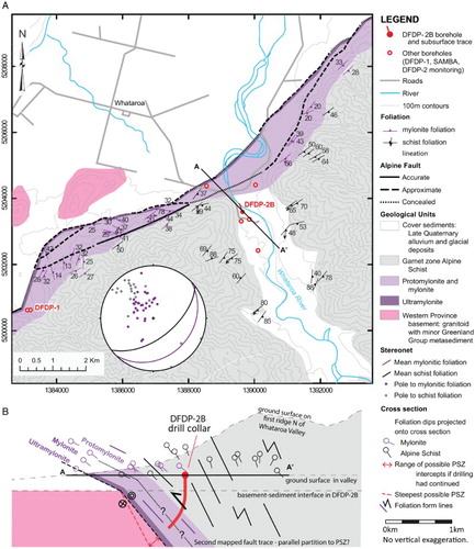
Figure 3. Compilation of samples and structural and chemical datasets collected from the DFDP-2B Borehole, bracketed by inferred lithological unit. A, Sample profile, wherein each dot represents a 2 m interval over which cuttings were collected. B–G summarise structural features noted during onsite logging and compiled then extracted from the DIS. In particular, note that D is a comparison of quartz recrystallised grain sizes obtained onsite by the linear intercept method with those subsequently obtained by EBSD-based methods and that surface data were projected onto this figure assuming the Alpine Fault would have been intercepted at 1100 m MD in DFDP-2B. The microstructural data illustrated in F were only gathered below 500 m MD because onsite protocols developed with time. H, General lithological profile, constructed as a summary during the onsite operation, with compositional sub-division of bedrock units from the ‘weight proportion of chips analysis’ carried out onsite. I, Chip proportions. Quartz-rich is >40 wt% quartz + feldspar chips, mica-rich is >40 wt% mica chips. Horizontal grey bands extending across the entire figure coincide with intervals that were identified as quartz-rich. Note inversion of scale for wt% mica. Mismatches of the quartz + feldspar curves are the proportion of chips with intermediate compositions (from 40–60 wt% mica). J–L are compositional data derived from analyses of sub-samples, as labelled at the top of each column. Again, note the %mica scales increase toward the left. For D, E and I–L, weighted averages, mostly calculated over a 50 m moving window, as noted near the top of each panel, demonstrate broad/general trends. Notable structural and lithological features compiled from drill logs are indicated in G and H, respectively. Data sources: A–I—datapack provided with Sutherland et al. (Citation2015); J—supplementary data Table S2; K—; L—; D also includes EBSD data from supplementary data Table S3.
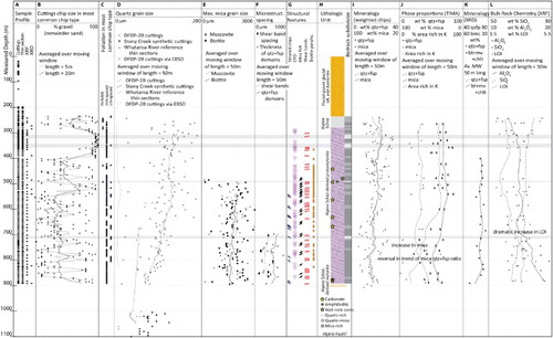
Table 3. Summary of samples collected from DFDP-2B.
Sample descriptions and analyses
During DFDP-2B, geological team members carried out hand specimen and microscopic descriptions of mineralogy and structure on the drillsite. Subsequently, sub-samples were taken and analysed by electron beam methods such as energy dispersive spectroscopy (EDS)—to further quantify mineralogy—and electron backscatter diffraction (EBSD)—to further map and quantify microstructures. Mineralogical and geochemical information was also acquired, respectively, by X-ray fluorescence spectroscopy (XRF) and X-ray diffraction (XRD). Further details of these descriptions and analyses can be found in the methods section of the supplementary data.
Compositional information
An estimate of composition of each cutting sample was determined by measuring the weight proportion of quartz + feldspar:mica-rich chips onsite (I). Proxies to these estimates were derived from the compositional data collected offsite. For the XRD data, we compared the proportion of quartz + feldspar:muscovite + biotite + chlorite. For the XRF data, we compared the Al2O3:SiO2 ratio (L). We chose these oxides rather than K2O (which should be common in micas) because Al2O3 and SiO2 are comparatively immobile in crustal fault zones (Gresens Citation1967; Grant Citation1986). The plot of major element oxides in L does not distinguish whether Al2O3 is present in plagioclase or phyllosilicates, but simply reflects the relative abundance of quartz compared to these other major phases.
Structural information
Structural and microstructural characteristics that we considered would be diagnostic of our position within the typical Alpine Fault Zone fault rock sequence (Toy et al. Citation2015) were documented in hand specimen and thin section. Additionally, the mean grain size of quartz in cuttings fragments was measured onsite using a petrographic microscope and the linear intercept method (Exner Citation1972). Structural descriptions of drill cores were also undertaken. Further details about these analytical methods and the types of data recorded can be found in the methods section of the supplementary data.
Electron backscatter diffraction data were also collected from offsite thin sections. These data were processed using both CHANNEL5 HKL software (see Bestmann & Prior Citation2003) and the MTEX crystallographic texture analysis and modelling toolbox for Matlab (Bachmann et al. Citation2010; http://mtex-toolbox.github.io). Again, further details of these analyses are provided in the methods section of the supplementary data.
Results
Cuttings descriptions
The cuttings samples mostly comprise sub-angular to angular chips. Chip grain size (not the size of constituent mineral grains) was visually estimated as a percentage of gravel (>2 mm), sand (>60 µm and <2 mm), and clay (<60 µm) (B). Silt-sized cuttings were not differentiated because particles of this size would have been introduced by the circulating drilling mud. Clay fractions were almost never identified in the washed basement cuttings samples because they were removed during the washing process. Ratios of gravel:sand average 52:48%, but there are substantial variations, with ratios ranging from 0:100% to 100:0%. For example, particularly fine-grained cuttings (>90% sand) were recovered between 493 and 502 m MD, while the majority of cuttings recovered between 300 and 400 m MD are >90% gravel sized.
In each washed and dried bulk cuttings sample we differentiated distinct types of chips, based on their colour and mineralogy. Common chip types that we described and were available for use in the DIS database were ‘quartz’, ‘muscovite-biotite-quartz schist’, ‘biotite-muscovite-quartz schist’, ‘grey fine-grained schist (QFSP mica schist)’, ‘sugary quartz-feldspar (QFSP mica schist)’ and ‘carbonate’ (illustrated in the Example VCutD form in the supplementary data; QFSP = quartzofeldspathic). Chip colours (again selected from descriptive terms we defined in the DIS) are typically shades of cream, grey to black and, more rarely, brown or orange. Examination of the described chip sizes and colours against depth over the >600 m of drilled bedrock sequence reveals no systematic variations that could be interpreted to reflect protolith or structural grade. Proportions of common minerals were also estimated. Structural characteristics documented include: the nature of tectonite foliation—which is typically either planar or undulating and hairline to mm-spaced, continuous or absent; the presence of vein fragments; and the presence of striated and undulating surfaces, shear bands and rarely mica streak or shear band intersection lineations (as defined by Toy et al. Citation2012b).
Thin section descriptions confirmed a mineral phase composition dominated by quartz, with plagioclase feldspar, muscovite, biotite and more rarely chlorite, garnet and calcite, with accessory minerals including apatite, graphite, ilmenite, rutile, titanite, zircon and unidentified opaques.
Quartz microstructures typically comprise remnant grains hundreds to thousands of micrometres in length, with undulose extinction and interlobate grain boundaries. Polygonal aggregates comprising smaller (mostly <100 µm), more equant grains lacking undulose extinction, which we infer are ‘recrystallised’ grains, were increasingly noted with increasing depth, as were highly elongated grain shapes commonly referred to as ‘ribbon grains’ (Passchier & Trouw Citation2006). A Crystallographic Preferred Orientation (CPO) was noted in many of these polygonal aggregates. Plagioclase crystals are mostly a few hundred micrometres in size, but could be larger (e.g. 1000 µm in DFDP-2B_618-620_CU [ICDP5052EXIM601] Footnote1). They are mostly intermixed with quartz in foliation domains in schists and protomylonites.
In non-mylonitic Alpine Schists and protomylonites, biotite and muscovite are generally ‘elongated’ grains, clustered in planar, millimetre-thick foliation domains. Graphite grains are distributed along muscovite basal planes. Biotite porphyroclasts 1–2 mm long typically contain inclusions of opaque minerals (graphite), fine mica and quartz. These define inclusion trails, commonly with curved habit like the form surface of microfolds, but elsewhere planar. Muscovite and biotite fish were typically recognised at MD ≥ 532 m. There is no systematic change in the maximum size of muscovite and biotite grains, but fine ‘recrystallised biotite’ grains were increasingly noted at MD >775 m. Large (>1 mm diameter) biotite porphyroblasts prevail throughout the drilled depth range, but become less common with increasing depth, presumably because they are more extensively recrystallised. Chlorite was first observed in thin sections at 460 m MD and, at greater depths, was described as ‘replacing’ or ‘in association with’ biotite or infilling cracks in garnet. Garnets are variably present throughout the drilled bedrock sequence.
Mineralogy was documented onsite, but mineral abundances were not recorded, so the thin section analyses did not result in a systematic dataset that highlights mineralogical variation. This decision was motivated by the observation that, in nearby outcrops (e.g. Stony Creek, Gaunt Creek; ), in DFDP-1 core and in synthetic cuttings, the structural character of the sequence changes systematically with distance from the PSZ, whereas modal mineralogy does not (Little et al. Citation2002, Citation2015; Toy Citation2008; Toy et al. Citation2008, Citation2015). Our primary aim was to identity proximity to the PSZ. At the rate of drilling, this aim was best addressed by using the time available for microscopic work to make systematic microstructural descriptions and measurements. Chips comprising altered (to chlorite and epidote) amphibolite were observed in DFDP-2B_492-494_CU [ICDP5052EXEL601] (E and F) and cataclasite in DFDP-2B_878-880_CU [ICDP5052EXQP601] (described further below), but in general the same minerals were found to be present in each sample.
Figure 4. Photographs of selected cuttings samples collected on the drillsite, from a range of depths through the borehole. The background grid is spaced at 1cm. A, DFDP-2B_265-267_CU [ICDP5052EUG8001], is the shallowest sample confidently interpreted as bedrock. B, DFDP-2B_624-626_CU [ICDP5052EUST001], is typical of samples collected at intermediate depths through the bedrock sequence. C, DFDP-2B_708-710_CU [ICD5052EUNW001] and D, DFDP-2B_890-892_CU [ICDP5052EUP1101] highlight the typical range of compositions and particle sizes. C is mica-rich and fine-grained, while D is quartz-rich and coarse-grained.
![Figure 4. Photographs of selected cuttings samples collected on the drillsite, from a range of depths through the borehole. The background grid is spaced at 1cm. A, DFDP-2B_265-267_CU [ICDP5052EUG8001], is the shallowest sample confidently interpreted as bedrock. B, DFDP-2B_624-626_CU [ICDP5052EUST001], is typical of samples collected at intermediate depths through the bedrock sequence. C, DFDP-2B_708-710_CU [ICD5052EUNW001] and D, DFDP-2B_890-892_CU [ICDP5052EUP1101] highlight the typical range of compositions and particle sizes. C is mica-rich and fine-grained, while D is quartz-rich and coarse-grained.](/cms/asset/30c68d65-7b5b-4bcd-9313-d637a62c56c3/tnzg_a_1375533_f0004_c.jpg)
Notable structural features and variations
Significant mesostructural characteristics included a gradual reduction in the thickness of foliation domains (from mm to hairline spaced) with increasing drilled depth and the presence of striated or undulating surfaces. These were first noted in cuttings samples at 546 m MD and became increasingly common from 590 m MD (G). A cataclasite fragment was sampled at 878–880 m MD [ICDP5052EXPP601]. This fragment is probably derived from one of the numerous minor faults and fracture zones commonly seen in surface exposures within the hanging wall of the Alpine Fault. As we were collecting only a proportion of the total cuttings created by the drilling process, it is unlikely that we would have been able to sample all such structures from the cuttings alone. However, they are readily identifiable in borehole televiewer imagery (Massiot Citation2017).
DFDP-2 wall rock drill cores from MD = 475.5–476.9 m consist of a dark grey, mica-rich, quartzofeldspathic protomylonite with an average grain size of 2–3 mm. Quartz porphyroclasts display recrystallisation textures, while plagioclases have largely brittle fabrics. Shear bands are abundant. Biotite and muscovite grains are approximately 3–5 mm in length and are aligned on foliation and shear band surfaces. Rare garnets are up to 2 mm in diameter. Quartz pods and ribbons occur sub-parallel to the mylonitic foliation with thicknesses of 0.5–1 cm (G and B).
Figure 5. Key structures from one of the wall rock core sections (23_Z_2; 475.5-476 m MD [ICDP5052ES06HU2]) illustrated through A scan of the core and B tracing of the outer surface of the core. C–E, Relative orientations of foliations (black dashed great circles), shear bands (yellow great circles) and prominent quartz veins (red great circles) and their associated poles for all three main core sections demonstrated on lower hemisphere equal area projections. Note that, because the cores were not oriented, these plots are in a reference frame fixed to that core section only. In each case, the top of the stereonet is parallel to the arbitrary reference line scribed along the length of each section and the core axis plots in the centre of the stereonet.
![Figure 5. Key structures from one of the wall rock core sections (23_Z_2; 475.5-476 m MD [ICDP5052ES06HU2]) illustrated through A scan of the core and B tracing of the outer surface of the core. C–E, Relative orientations of foliations (black dashed great circles), shear bands (yellow great circles) and prominent quartz veins (red great circles) and their associated poles for all three main core sections demonstrated on lower hemisphere equal area projections. Note that, because the cores were not oriented, these plots are in a reference frame fixed to that core section only. In each case, the top of the stereonet is parallel to the arbitrary reference line scribed along the length of each section and the core axis plots in the centre of the stereonet.](/cms/asset/5ce17176-fc2c-47ef-b65a-3197bac1e1e8/tnzg_a_1375533_f0005_c.jpg)
In microstructural descriptions of onsite thin sections of cuttings samples, shear bands were noted throughout the drilled sequence. Shear band density increased with depth and they were first qualitatively described as ‘abundant’ at MD = 494 m. Foliation domain spacing and shear band spacings were irregularly noted in descriptions, but not documented in a systematic way, so it is difficult to assess how these vary with increasing depth and inferred mylonite grade (F).
Analysis and description of wall rock drill cores reveals closely spaced mylonitic foliations and shear band surfaces. Foliation spacing is approximately 2–4 mm (B). Shear bands are generally spaced at a sub-centimetre scale and form an average angle of 30 ± 4° with the mylonitic foliation. Quartz pods display ductile textures, including rare intrafolial isoclinal folds and a dynamically recrystallised matrix. In some locations, quartz pods define the mylonitic foliation. Foliation and shear bands are overprinted by brittle fractures, generally at a low angle to the foliation. These fractures may be natural or drilling-induced. Linear fabrics are defined by aligned mica on both foliation and shear surfaces. Brittle slickenlines were not observed.
Figure 6. A and B, Scans of thin sections made on the drillsite. A, DFDP-2B_213-215 m MD [ICDP5052EX3L601] displays typical characteristics of Alpine Schist, such as graphitic inclusions in porphyroblasts—in biotite (purple arrowed chip) these are distinct bands reflecting a Mesozoic spaced foliation (Little et al. Citation2002), while in plagioclases they are more distributed but still represent intersection of a planar foliation and the section surface (pink arrowed chip), whereas B, DFDP-2B_812-814 m MD [ICDP5052EX0P601], displays evidence of mylonitic deformation, particularly sigmoidal clasts (indicated by purple arrows), whose overall shape has been affected by the operation of C-type shear bands (e.g. between the pink/red arrows). C and D are K2O maps of the surfaces of pucks from which these thin sections were cut. These also demonstrate textural differences between C, Alpine Schist sample DFDP-2B_264-266_CU [ICDP5052EUF8001] and D, mylonite DFDP-2B_852-854 m MD [ICDP5052EXXP601]. E and F illustrate an amphibolite chip observed in DFDP-2B_492-494_CU [ICDP5052EXIK601] in plane polarised and cross polarised light, respectively. The latter highlights a crenulated foliation.
![Figure 6. A and B, Scans of thin sections made on the drillsite. A, DFDP-2B_213-215 m MD [ICDP5052EX3L601] displays typical characteristics of Alpine Schist, such as graphitic inclusions in porphyroblasts—in biotite (purple arrowed chip) these are distinct bands reflecting a Mesozoic spaced foliation (Little et al. Citation2002), while in plagioclases they are more distributed but still represent intersection of a planar foliation and the section surface (pink arrowed chip), whereas B, DFDP-2B_812-814 m MD [ICDP5052EX0P601], displays evidence of mylonitic deformation, particularly sigmoidal clasts (indicated by purple arrows), whose overall shape has been affected by the operation of C-type shear bands (e.g. between the pink/red arrows). C and D are K2O maps of the surfaces of pucks from which these thin sections were cut. These also demonstrate textural differences between C, Alpine Schist sample DFDP-2B_264-266_CU [ICDP5052EUF8001] and D, mylonite DFDP-2B_852-854 m MD [ICDP5052EXXP601]. E and F illustrate an amphibolite chip observed in DFDP-2B_492-494_CU [ICDP5052EXIK601] in plane polarised and cross polarised light, respectively. The latter highlights a crenulated foliation.](/cms/asset/8825f7d7-94c2-4176-bb47-3eac64653f8c/tnzg_a_1375533_f0006_c.jpg)
Indicators of ductile simple shear strain
Exhumed Alpine Fault mylonites accommodated progressively higher finite ductile shear strains toward the principal slip zone (Norris & Cooper Citation2003), resulting in progressive changes in structure, microstructure and proportion of dynamically recrystallised material. Some of the changes most prominent in outcrop, such as phase mixing and reducing intensity of a spaced foliation (Toy et al. Citation2011), were not specifically noted in the cuttings samples. This is probably because most of the chips are smaller than the spacing of the foliation domains. However, there is sufficient observational evidence to correlate the cuttings with the previously-defined ductile fault rock sequence. Features indicative of ductile shear strain that were noted include: the number of chip surfaces showing undulating habit with grooved/striated shiny surfaces increased with depth (G); and, in thin section, the proportion of inherited pre-mylonitic porphyroblasts, i.e. >1 mm long primarily biotite grains containing graphitic inclusion trails, reduced with increasing depth in the borehole (G). The average grain size of the largest muscovites and biotites also gradually decreased with depth (E), as did the spacing of shear bands (F). Graphite was found to be redistributed onto grain boundaries, albeit still as small (typically 1–5 µm), dispersed grains. Sporadic sigmoidal quartz domains and micaceous layers deflected into shear bands were also observed (G).
The most quantitative indicator of increasing ductile shear strain that could be correlated to outcrop samples was the mean quartz grain size measured in nearly pure quartz fragments by the linear intercept method. As demonstrated in D, this measured grain size showed a slight reduction throughout the sequence interpreted as protomylonite, then a fairly dramatic reduction below 100 µm at the inferred protomylonite-mylonite boundary at 830 m MD. The same numerical change had been previously observed in synthetic cuttings from Stony Creek ().
The shear band and foliation spacings and relative orientations documented in the DFDP-2B cores are consistent with those previously described in outcrops in proximity to the Alpine Fault. Norris and Cooper (Citation2003) and Toy et al. (Citation2013) estimate an order of magnitude increase in shear strain through the mylonite zone of the Alpine Fault in the central and Southern Alps, with simple shear strains increasing from γ ∼ 12 in protomylonites to γ ∼ 150 in ultramylonites (for pure shear stretches perpendicular to the fault zone of S3 ∼ 0.29). Gillam et al. (Citation2013) report that only a proportion of these strains, γ ∼ 0.6-0.8, results from cumulative slip on shear bands in the distal mylonite zone at Tartare Stream, but the authors also demonstrate that the shear bands become more closely spaced toward the Alpine Fault and the foliation orientation coincides with the shear zone boundary. A shear strain gradient could not be detected in the short length of Whataroa DFDP-2 core. However, the 2–4 mm shear band spacing observed is fairly consistent with the 3–4 mm spacing in the distal mylonite zone of the Tartare Stream (Gillam et al. Citation2013).
Shear band and foliation spacing can also be affected by lithologic heterogeneities, particularly the thickness and strength of layered material or rigid porphyroclasts. For example, shear bands are more widely spaced and, thus, each accommodates higher slip in thick, stiff foliation domains (Gillam et al. Citation2013). In well-layered protomylonites of the DFDP-2 cores, foliation parallel quartz pods and ribbons are the stiffest material in these otherwise mica-rich rocks. Shear bands were not observed in the stiff quartz layers in the cores and this is likely an artefact of a wide shear band spacing and a limited observable area presented by drill cores, rather than a lack of shear bands, which were able to be measured in the intervening microlithons (). These measurements demonstrate a dihedral angle between shear bands and foliation in the borehole at Whataroa (30 ± 4°) that is the same as was recorded by Gillam et al. (Citation2013) (30 ± 1°), who report little variation in this angle through the mylonite shear strain gradient. Toy et al. (Citation2012b) found that the angle between the mean foliation and mean shear band plane in a geographically broader area, using datasets from outcrops at Gaunt Creek, Stony Creek and around the Waikukupa River (), is 26°, which is again fairly consistent with both measurements from DFDP-2B cores and the findings of Gillam et al. (Citation2013).
Late stage brittle fractures are predominantly sub-parallel to the mylonitic foliation (; Massiot Citation2017), suggesting that the anisotropic strength of the ductile fabric in the DFDP-2 cores influenced later brittle deformation patterns. Does this anisotropy have an influence on the orientations of all brittle structures that form in layered mylonites and ultramylonites adjacent to the Alpine Fault? In cores recovered from the DFDP-1A borehole and in DFDP-1B at depths 94.0–128.2 m (i.e. entirely within the hanging wall), Williams et al. (Citation2016) and Williams (Citation2017) observed that foliation-parallel fractures account for only 11% of fractures in units where a foliation exists (i.e. not including mechanically homogenous cataclasites). They concluded that fracture orientations non-parallel to foliation are symptomatic of the Alpine Fault damage zone, which has a nearly constant thickness of 160 m in this area.
Significant compositional variations
Major element analyses (XRF) and mineralogy (XRD) ( and , and ) indicate that the cuttings are derived from amphibolite facies Alpine Schist (Pitcairn et al. Citation2006). However, the full spectrum of Alpine Fault rock types observed elsewhere in outcrops and in DFDP-1 core was not recognised in the cuttings samples. Most of the rock types observed in the cuttings were mineralogically comparable to Unit 1 (i.e. grey and dark green Alpine Schist-derived ultramylonites) from DFDP-1 (), but displayed less well-developed microstructural indicators of ductile shear strain, as discussed below. There was also one chip sample of cataclasite similar to Unit 3 or 4 from DFDP-1.
Figure 7. Discriminatory plot based on variations in the major element oxide proportions Fe2O3+MgO and Al2O3/SiO2. Whole rock data from the Alpine Schist, Torlesse and Caples Terranes and the Aspiring Lithologic Association include analyses by Coombs et al. (Citation1985); Fagereng and Cooper (Citation2010); McClintock (Citation2000) and other open file data from the Petlab database http://pet.gns.cri.nz (Strong et al. Citation2016). DFDP-1 ‘alteration zone’ samples are defined as those taken from within 50 m of the fault PSZ in that drillcore (Boulton et al. Citation2017). DFDP-2B data are from cuttings samples analysed in this study ().
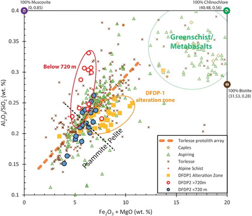
Table 4. Major element data measured by XRF.
Variations in mineralogy
Most cuttings samples are quartzofeldspathic in composition, i.e. primarily quartz, plagioclase, muscovite and biotite with rarer calcite, garnet and chlorite plus accessory phases, corresponding to the grey variant of Unit 1 (). The protolith is inferred to be the Torlesse Composite Terrane (Cox & Barrell Citation2007), mostly because the structural and transport history requires it, but also because distinctive minerals that would be diagnostic of other possible protoliths (e.g. abundant allanite or K-feldspar porphyroclasts would suggest Western Province granitoid as a protolith, while a high quartz:plagioclase ratio would suggest Greenland Group metasediments) are not observed. Only one cuttings thin section, in the sample recovered from 494–496 m MD [ICDP5052EXIK601] contains an epidote-chlorite-amphibole-rich clast. This mineralogy is similar to that of retrogressed amphibolite—the dark green variant of Unit 1 (). Amphibolite, generally in association with high pelite:psammite ratios, is a common constituent of the Aspiring Lithologic Association (Craw Citation1984), which is mapped at the drillsite in QMAP:Aoraki by Cox and Barrell (Citation2007).
At nearby Gaunt Creek, Toy et al. (Citation2008) determined amphibolite comprises >5% of the mylonite sequence. However, its comparative scarcity in DFDP-2B samples indicates that most of the schist we sampled has a ‘normal Torlesse’ quartzofeldspathic protolith, namely trench-fill sediments deposited on the Mesozoic Gondwana margin (Mortimer Citation2004). Similarly, although the drillsite is mapped in the K-feldspar zone of the amphibolite facies, no K-feldspar was observed either in thin section or in XRD. These observations indicate that revisions of the QMAP:Aoraki (Cox and Barrell Citation2007) may be locally required.
The mineralogy, chemistry and structure of the cuttings samples mostly change slowly and progressively with depth. The most obvious change occurs below c. 700 m MD, where the overall ratio of quartz + feldspar:mica chips subtly decreases (I). XRD data also suggest that chlorite + muscovite become more abundant compared to biotite beneath this depth (, K). However, we are wary about making interpretations of the nature of lithological change from the XRD data, because the proportion of chlorite indicated is greater than we qualitatively observed in thin sections of the same samples. Notably, chlorite was only described in thin sections below 460 m MD, but the XRD data suggest it is present by 405.7 m MD in similar abundance to deeper samples. The thin sections sample only a few chips, while the XRD data are measured on powders made by crushing at least 20 g of chips, so this may reflect a heterogeneous distribution of the mineral in the rock chips or an inhomogeneous mixing of cuttings.
Table 5. Mineralogical data measured by XRD.
These mineralogical changes should be reflected in chemical variations. We examined their potential significance based on major element oxide proportions derived by XRF, specifically considering the ratio of Al2O3/SiO2 to Fe2O3+MgO (), which is an indicator of primary sedimentary protolith variation. This allowed assessment of whether these changes are the result of a change in protolith or reflect chemical mass change. The possible protoliths, namely Alpine Schist, the Torlesse and Caples Terranes and the Aspiring Lithologic Association, are best fit by and lie around a trendline labelled as the ‘protolith array’ (Pitcairn Citation2004). Samples that lie substantially away from this protolith array have experienced secondary mobility of silica. Rocks lying above the trendline have experienced silica removal and those lying below the trendline have experienced silica addition. On this plot, psammites have Fe2O3+MgO values of <6 wt.%; pelites >6 wt.% and metabasic rocks >10 wt.%. DFDP-1 ‘alteration zone’ samples are defined as those taken from within 50 m of the fault PSZ in that drillcore (Boulton et al. Citation2017) and these plot below the protolith array indicating silica addition. DFDP-2 data from this study () show two distinct trends. Shallower than 720 m, cuttings samples lie along a similar array as the Torlesse Terrane (including its Aspiring Lithologic Association) protoliths and deeper than 720 m, cuttings samples lie above this trend, indicating a decrease in quartz and/or increase in muscovite.
Amphibolite facies, oligoclase-bearing Alpine Schist have average loss on ignition (LOI) of 1.4 ± 0.6 wt.% (Pitcairn et al. Citation2006). Our measurements for the top c. 700 m of the borehole are above this range (2.7 ± 0.4 wt.%), indicating that the protomylonite cuttings of the Alpine Fault Zone in the Whataroa Valley have higher volatile contents than the background, non-mylonitic Alpine Schist. Below 700 m, the LOI measurements made of cuttings from the borehole increase to 3.6 ± 0.6 wt.% (L), which likely reflects greater amounts of CO2 from carbonate minerals or of H2O or OH from phyllosilicate minerals, which commonly increase in modal proportion with proximity to the Alpine Fault, as noted in DFDP-1 boreholes (Sutherland et al. Citation2012; Townend et al. Citation2013; Toy et al. Citation2015). Petrographic evidence suggests the latter as the dominant source of this chemical signature, because carbonate minerals are uncommon in the cuttings (H). There is a sharp increase in LOI to 4.4% at 716 m MD, coincident with the change in the trend towards increasing Al2O3/SiO2 ratios (L and ).
Discussion
Interpretation of DFDP-2B cuttings data
A significant variation observed in DFDP-2B cuttings was in the quartz + feldspar:mica ratio or proxies for this ratio derived from major element analyses (XRF) and mineralogical analyses (XRD) ( and , and ). In general, the ratio of quartz + feldspar:mica or its proxies decreases with depth. However, some discrepancies between the compositional analyses are also apparent. Notably, (i) the XRD data show a continued gradual decrease in quartz + feldspar:mica toward the base of the borehole, (ii) TIMA (TESCAN Integrated Mineral Analyzer) and weight proportion of chip data show a trend reversal, i.e. a slight increase in quartz + feldspar:mica below 780 m MD (I–K) and (iii) TIMA and XRD data suggest much greater proportions of quartz + feldspar:mica overall than the weight proportion of chips analysis.
The ratios of Al2O3 to SiO2 and LOI to SiO2 increase down hole, alluding to a decrease in SiO2 from quartz and an increase in Al2O3 in micas and water associated with phyllosilicates. These XRF data (L and ) strongly indicate that compositionally distinctive samples recovered below c. 700–720 m MD are not a sliver of either Aspiring Lithologic Association or Alpine Fault alteration zone. Instead, we suggest these samples lie on a mixing line consistent with increasing proportions of muscovite and chlorite and that the variation may either reflect a slight increase in pelite:psammite ratio, depletion of silica by fluids circulating in late fractures or heterogeneous sampling of cuttings rich in phyllosilicates due to variations in borehole circulation parameters and chip size (B).
The modal compositions of cuttings samples are affected by the mineralogy of rock being drilled, the type of drill bit used and the sampling process. The increase in lag correction toward the base of the hole (Figure S1) reflects the increase in depth over which mud and entrained cuttings were transported to the surface, but the lag depth is relatively minor and there is no evidence for cuttings storage within the borehole. The sampling process, in which cuttings are sieved from drilling mud, may have resulted in under-sampling of small cuttings, introducing bias into our inference of rock type where certain components are more finely cut. In washed cuttings samples, pure quartzo-feldspathic cuttings tended to be the smaller particles, so an apparent increase in mica with depth could be interpreted as under-sampling of the quartzo-feldspathic component. However, in some samples, coarse-grained quartzo-feldspathic cuttings dominated () and the two thickest quartz-dominant layers were identified when coarse cuttings samples were collected at 300–350 m MD (shown as grey horizontal bands on B and I). The lack of independent constraints on overall mineralogy mean that hypotheses about sampling bias due to sieving cannot be verified. There were no major changes in drill bit type or sampling process below 547 m MD (Sutherland et al. Citation2015), so we are confident that relative changes in cuttings samples reflect changes in the rock type being drilled.
It is also important to note that identification of chips as quartz + feldspar or mica in the visual chip analysis only means that those minerals dominate the macroscopic appearance of that particular chip during its visual examination under the binocular microscope. These are not quantitative measurements of the modal mineralogy of the sample. The visual chip analyses were biased towards mica because the cuttings chips tended to lie flat on muscovite layers (I). Quartz segregations commonly lie between muscovite layers, but these were not accurately quantified because the chips had to be turned on their side under the microscope to see the quartz. Manipulating each cutting was often too time consuming to be done at the rate that new samples were acquired.
Testing methods for data processing and analysis
One of the advantages of such large datasets is that they are ideal for testing methodologies for automated data collection to determine consistency across the different datasets and also allow for evaluation of the various analytical methods. We tested (i) methods for calculating the recrystallised grain size of quartz and (ii) methods to determine modal mineralogy and broad mineralogical variation from EDS, XRD and XRF analyses.
Quartz grain size analysis from EBSD data
In EBSD datasets there is a high probability that grains comprising only a few pixels are indexing errors and so it is common to filter out the finest fraction from the dataset before a mean is calculated. Halfpenny et al. (Citation2006) suggested that a statistically robust grain size data can only be obtained from CHANNEL software if grains containing fewer than five pixels are removed, which we have done by setting a minimum pixel size of 13 when detecting grains. Consequently, the smallest grains included in the CHANNEL grain size distribution (C) are 9.8 µm in diameter. MTEX uses a more computationally robust method (Cross et al. Citation2015) that removes both grains comprising four or fewer pixels and those that are poorly constrained based on the fraction of their area indexed. The grain size distribution illustrated in D uses this filtering method. The mean grain size from the MTEX dataset (35.8 ± 53 µm) is larger than that determined by CHANNEL (26.7 ± 33 µm). Kidder et al. (Citation2014) determined a dominant quartz grain size in central Alpine Fault mylonites of approximately 40–60 µm based on analysis of 250 mylonite samples. The grain size determined by MTEX is most consistent with this, suggesting that its filtering method is more robust than CHANNEL’s. We, thus, propose that noise reduction in CHANNEL followed by grain segmentation and analysis in MTEX will produce the best outcome for grain size measurements. Procedurally, it is also important to output a map of the detected grains and visually compare this to the input data to verify that processing artefacts have not been introduced in any such analysis.
Figure 8. EBSD maps. All parts of the figure relate to DFDP-2B_520-532_CU [ICDP5052EX7L601]. A, EBSD-derived phase map generated in CHANNEL software. B, EBSD-derived phase map generated in MTEX software. In both cases colouring is related to orientation. C, Grain size distribution for this sample generated in CHANNEL software, for all grains >9.8 µm diameter. Note x-axis labels are at the centres of 5 µm wide bins; D, grain size distribution determined by MTEX.
![Figure 8. EBSD maps. All parts of the figure relate to DFDP-2B_520-532_CU [ICDP5052EX7L601]. A, EBSD-derived phase map generated in CHANNEL software. B, EBSD-derived phase map generated in MTEX software. In both cases colouring is related to orientation. C, Grain size distribution for this sample generated in CHANNEL software, for all grains >9.8 µm diameter. Note x-axis labels are at the centres of 5 µm wide bins; D, grain size distribution determined by MTEX.](/cms/asset/54e2ad44-ba05-4445-9609-ea6518ad4a2f/tnzg_a_1375533_f0008_c.jpg)
We generally find that grain sizes measured by a linear intercept method onsite (and previously on synthetic cuttings) are dissimilar to those determined by subsequent EBSD mapping—the latter are generally much smaller. However, the two datasets show local increases at comparable depths (D). This could be because we analysed more quartz grains that are found in mineralogically mixed layers in the EBSD data than in the chips, where we focused on nearly pure quartz chips. Grain boundary pinning (e.g. Herwegh & Berger Citation2004) generally results in a smaller grain size in polyphase domains compared with monophase (‘pure’) mineralogical layers (Little et al. Citation2015). It is also likely that the smallest grains were not easily visible in the thin sections by the geologist carrying out the linear intercept analysis, so these results are weighted toward larger grains. Overall, we do not recommend that any of our methods are used for stress determinations by recrystallised grain size piezometry (e.g. Holyoke and Kronenberg Citation2010). However, the methods employed in this study are appropriate for tracking variations that result from accommodation of ductile strain provided they are properly calibrated to similar measurements made in outcrop samples.
Modal mineralogy
In EDS maps, the AZtec software version 3.1 (Oxford Instruments Nanoanalysis Citation2013) available during these analyses automatically segmented quantitative oxide proportion maps into a set of minerals not recognised in thin sections. For example, large areas of each map were assigned to be SiO, leaving only high concentrations of typically more minor elements, such as Fe, from which to construct other minerals. In the TIMA maps, the Mineral Liberation Analysis (MLA) method described in the methods section of the supplementary data yielded substantial areas of clays and zeolites (e.g. ferrosapponite, schorl, three types of allanite, nepheline; Figure S2B). Automated PhaseID was only recently implemented in AZtec and the TIMA instrument and the associated software were only recently developed. As with any automated routine (cf. EBSD; Prior et al. Citation1999), rapid advances in the quality of the output are expected in the next few years. In these particular datasets, it is likely that more careful examination of the automatically detected minerals by the software operator, then introduction of appropriate corrections to the software, would yield more realistic results, consistent with other geochemical data. Note that operator-informed software corrections were not possible in the version of AZtec available during acquisition and processing of DFDP-2B datasets, but this functionality has been implemented in the most recent AZtec versions (versions 3.2 and 3.3).
Do these analytical methods nevertheless provide reasonable estimates of the bulk composition? If they do, we expect the sum of the area of minerals automatically assigned as micas should show similar variation to the areas rich in potassium (K). We carried out this analysis for the TIMA maps, demonstrating a fairly good correlation (the shapes of the curves in J are similar). However, the area rich in K within TIMA maps shows a gradual decrease throughout the borehole, whereas the sum of minerals automatically indexed as mica gradually increases below 700 m MD, which could reflect chloritisation of biotite. In summary, the onsite analysis of quartz + feldspar:mica ratios yields similar variations down hole to those indicated by the proxies to this derived from EDS, XRF and XRD, notably a gradual decrease in the quartz + feldspar:mica ratio with depth and a very similar shape to the moving window average curves for mica proportion from the onsite analysis of chips (I) and both mica and K-rich areas (J) derived from the TIMA maps. This suggests all these methods are appropriate indicators of compositional variation.
Implications for interpretation of other continuous datasets
Both the estimates of quartz + feldspar:mica proportion made on the drill site and the subsequent XRD and XRF analyses (I, K and L) indicate a general decrease in quartz + feldspar:mica with depth in the borehole. This gradual change should be detected in variations in the wireline geophysical logs. Higher resolution variations in composition, unaffected by cuttings mixing and lag, may also be resolved in the wireline data.
In DFDP-1, Townend et al. (Citation2013) identified that the geophysical parameters most strongly correlated to lithological variations were bulk electrical properties and natural gamma. They noted they expected electrical properties to be sensitive to phyllosilicate content, while natural gamma particularly varies in response to the proportion of K+ ions, which mostly reflects phyllosilicate content but is also sensitive to the presence of K-feldspar.
It is also possible that the strength of the developed tectonite fabrics, which reflects the strain they have accommodated, particularly the distribution of micas within the samples, will affect the rate and anisotropy of elastic wave propagation through the borehole wall rocks (e.g. Christensen & Okaya Citation2007; Dempsey et al. Citation2011). We strongly recommend that comparisons be made between the microstructural proxies to strain and tectonite fabric intensity, such as quartz grain size and downhole measurements of elastic properties in the future.
A rigorous comparison among the geological, geochemical and wireline geophysical logs is beyond the scope of this contribution, but such an analysis is underway by others (e.g. Massiot Citation2017). The datasets presented here, particularly those demonstrating or acting as proxies to variation in quartz + feldspar:mica proportion with depth, provide an important baseline for those researchers.
Prediction of fault rock sequence with further drilling
Observations made during the DFDP-2B geology study suggest that this borehole terminated after having penetrated c. 63 m (MD) of Alpine Fault mylonites, based on interpretation of the change in quartz grain size. In nearby outcrops, mylonites + ultramylonites + cataclasites have mapped true structural thicknesses of 530 m (Gaunt Creek), 430 m (Stony Creek) and 550 m (Parker Creek), but, elsewhere, such as Hare Mare and Doughboy Creeks (), late brittle faults cause excision of parts of the sequence, so there are only 100–250 m of mylonites + ultramylonites + cataclasites (Toy Citation2008). We interpret that, by 893 m MD, DFDP-2B had drilled to a structural distance (perpendicular to foliation) of 200–400 m from the PSZ of the Alpine Fault Zone. Since the hole was not vertical and the foliation dips steeply SE, the vertical distance would be greater. This allows us to tentatively position a PSZ at a depth of 1100 m MD on and and, by back-calculating distance from a PSZ, correlate between borehole measurements and those from other outcrops, such as quartz grain size data from Stony Creek, illustrated in D. This interpretation of structural position is supported by the geochemical indications ( and section Variations in mineralogy) that the fault’s alteration zone, which has a thickness of <50 m in DFDP-1 cores and less than this in most outcrops (Toy et al. Citation2012a), was not sampled. This is a minimum estimate of the PSZ depth, which could range up to 1300 m MD.
The DFDP-2B borehole terminated further from the Alpine Fault’s PSZ than the uppermost (cataclasite) rocks encountered in the DFDP-1A and DFDP-1B boreholes. We infer that further drilling in DFDP-2B would have yielded progressively more fractured and incohesive mylonite, then ultramylonite comparable to Units 1 and 2 in DFDP-1 (Toy et al. Citation2015), followed by cataclasites and then PSZ gouges. A composite log demonstrating our preferred correlation of the sequences encountered in the two phases of drilling is illustrated in . This reveals a missing (undrilled) section between the base of DFDP-2B and the uppermost core recovered from DFDP-1 of at least 120 m and possibly as much as 320 m. More accurate estimates of the position of the base of DFDP-2B with respect to the PSZ may be derivable from analysis of fracture orientations and fillings. Based on observations made in the DFDP-1 boreholes and in outcrop, Williams (Citation2017) defined the Alpine Fault damage zone as a 100–160 m wide interval of relatively dense clay-filled fractures of a broad range of orientations, rather than sub-parallel to foliation. We considered whether we could derive this information from the DFDP-2B logging data, but these do not yield distinctive petrophysical or structural features, so such analysis is unlikely to be fruitful and additional drilling seems required to log and core the entire hanging-wall transect and calibrate the mineralogical, geochemical and petrophysical data sets. Future analyses of the records gathered on three borehole seismometers arrayed within a 1 km radius of DFDP-2B may also allow resolution of fault zone structure through tomographic and fault zone guided wave analyses (cf. Eccles et al. Citation2015).
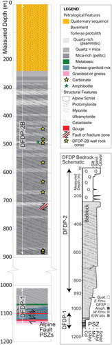
Figure 9. Composite summary lithological log of DFDP-1 and DFDP-2, demonstrating the proportion of the Alpine Fault Zone sequence able to be accessed for future research through these two sample sets. We have simplified the range of lithologies identified in DFDP-1 by Toy et al. (Citation2015) in order to display them at this scale and to best demonstrate relationships to DFDP-2 samples. Major structural and chemical features are highlighted by annotations at the right of the column. DFDP-1 was positioned on this column based on the assumption that the Alpine Fault PSZ would have been encountered after a further 200 m of drilling in DFDP-2B. As discussed in the text, this is a minimum estimate. A maximum of 400 m would yield a PSZ at 1300 m MD. A simplified schematic version of the lithological log is presented at the lower right.
As well as allowing correlation to DFDP-1 and outcrop, the estimate of the depth at which the PSZ might have been intercepted if DFDP-2B had continued provides a constraint on fault dip. In general, the Alpine Fault PSZ is inferred to be parallel to the mean mylonitic foliation (e.g. Norris & Cooper Citation2007; Toy et al. Citation2012b). The average mylonitic foliation in the area surrounding the Whataroa Valley () is shallow-dipping (26°), but this is inferred to be a result of collapse onto the unsupported footwall during over-thrusting, as is typically observed in outcrops to the north of the Whataroa River. Foliation dip probably steepens with increasing depth to match a mean dip of 50° of distal hanging wall mylonitic foliation attitudes along this section of the Alpine Fault (Toy et al. Citation2012b; Gillam et al. Citation2013). The average hanging wall schist foliation in outcrops in this area dips 59° (B) and analysis of borehole televiewer data in DFDP-2B reveals an average schist and protomylonite foliation dip of 60° (Massiot Citation2017), but elsewhere along the central Alpine Fault these foliations typically dip more steeply than those of the mylonites, so we do not think these data constrain the PSZ dip. A PSZ with a dip of 50° is illustrated by the black dashed line in B. If this interpretation is correct, DFDP-2B should have intercepted the fault PSZ just before 1100 m MD. During planning of DFDP-2, it was considered possible that the fault PSZ dips more steeply than this, either because there is a strike-slip segment of the Alpine Fault crossing the Whataroa River (Barth et al. Citation2012; Norris et al. Citation2012) or because the mean dip of the Alpine Fault at depth in this area is particularly steep (Little et al. Citation2005). Linking a fault position in the near-surface consistent with the observed steepening of foliation dips a short distance into the hanging wall, with a maximum PSZ intercept at 1300 m MD, now allows us to constrain a maximum feasible fault PSZ dip of 62° (B).
Conclusions and future directions
The onsite lab and procedures carried out during DFDP-2B yielded a rich array of samples, descriptions and datasets. These data were usefully compared to the offsite analyses to better understand the ability of various analytical methods to document true variation in the fault rock sequence. Our routine analyses have also yielded baseline datasets that provide a framework of lithological and structural information within which to interpret and provide a geologic context for the wide variety of continuous datasets that were gathered during DFDP-2B.
The drilled sequence comprises Alpine Schist, protomylonite and mylonite derived from a metasedimentary Torlesse Composite Terrane protolith. No samples were returned from Alpine Fault ultramylonites, cataclasites or alteration zone in DFDP-2 (Units 2–5 in Toy et al. Citation2015).
Structural features of cuttings chips could be correlated with outcropping sequences of schist-protomylonite-mylonite from nearby natural exposures. When considered in the context of complementary outcrop mapping, there is a high level of confidence in the inference of the proximity to the fault reached by the DFDP-2B drill hole. The Alpine Fault PSZ target is estimated to have been within 200–400 m of the end of hole. This estimate also constrains the maximum dip of the Alpine Fault in the Whataroa Valley to be 62°.
The combined sample sets from DFDP-1 and DFDP-2B do not yet offer a complete sample of the Alpine Fault Zone rocks and their protolith. We recommend that the drilled samples should be supplemented from outcrops in future targeted studies addressing scientific hypotheses about ductile shear zones and ductile-brittle fault zone architecture. Ideally, further drilling of the fault zone will be able to address this deficit.
SF1: Suppl Data to “Bedrock Geology of DFDP-2B, Central Alpine Fault, New Zealand”, including supplementary methods, Information on reference frames and corrections, and protocols for thin section preparation and scanning electron microscopic analyses
Download PDF (2.1 MB)SF2: Table S1. Time vs. depth during drilling, with lag dip corrections
Download Comma-Separated Values File (32.4 KB)SF3; Table S2. EDS data acquired using TIMA and phases detected by MLA
Download MS Excel (17.9 KB)SF4: Table S3. EBSD grain sizes.
Download MS Excel (10.7 KB)Acknowledgements
We thank the Friend family for land access and the Westland community for support; Schlumberger for assistance with optical fibre technology; the CNRS University of Montpellier wireline logging group of Pezard, Henry, Nitsch and Paris; Arnold Contracting; Eco Drilling; and Webster Drilling.
This manuscript was greatly improved in response to suggestions by Andy Nicol and another anonymous reviewer, as well as substantial comments from the Editor, Nick Mortimer. Helpful suggestions were also made by Diane Moore and Brooks Proctor. We are very grateful for these contributions.
Disclosure statement
No potential conflict of interest was reported by the authors.
ORCID
Virginia Gail Toy http://orcid.org/0000-0002-7621-2064
Rupert Sutherland http://orcid.org/0000-0001-7430-0055
John Townend http://orcid.org/0000-0002-7017-620X
Michael J. Allen http://orcid.org/0000-0001-5068-3661
Austin Boles http://orcid.org/0000-0003-3072-3309
Carolyn Boulton http://orcid.org/0000-0003-0597-6152
Brett Carpenter http://orcid.org/0000-0002-3451-2528
Simon C. Cox http://orcid.org/0000-0001-5899-8035
Daniel R. Faulkner http://orcid.org/0000-0002-6750-3775
Angela Halfpenny http://orcid.org/0000-0001-6560-3134
Martina Kirilova http://orcid.org/0000-0002-1359-9193
Timothy Little http://orcid.org/0000-0002-5783-6429
Benjamin Melosh http://orcid.org/0000-0002-0024-5898
Catriona D Menzies http://orcid.org/0000-0003-3268-0007
Luiz Morales http://orcid.org/0000-0002-8352-850X
Andre Niemeijer http://orcid.org/0000-0003-3983-9308
David Prior http://orcid.org/0000-0002-4653-2112
Katrina Sauer http://orcid.org/0000-0001-5668-7997
Norio Shigematsu http://orcid.org/0000-0001-8028-2738
Damon A. H. Teagle http://orcid.org/0000-0002-4416-8409
Robert Valdez http://orcid.org/0000-0002-7992-3515
Jack Williams http://orcid.org/0000-0001-6669-308X
Laura-May Baratin http://orcid.org/0000-0001-5687-6210
Nicolas Barth http://orcid.org/0000-0001-5161-3534
Carolin Boese http://orcid.org/0000-0002-2383-2219
Calum J. Chamberlain http://orcid.org/0000-0003-2317-2609
Ronald Conze http://orcid.org/0000-0002-8209-6290
Mai-Linh Doan http://orcid.org/0000-0002-6437-9756
Jennifer Eccles http://orcid.org/0000-0002-9303-348X
Julia Grochowski http://orcid.org/0000-0002-7795-4852
Anton Gulley http://orcid.org/0000-0003-0759-1897
Jamie Howarth http://orcid.org/0000-0003-4365-0292
Lucie Janku-Capova http://orcid.org/0000-0003-4882-2380
Tamara Jeppson http://orcid.org/0000-0001-5526-5530
Robert Langridge http://orcid.org/0000-0002-5092-0468
Cécile Massiot http://orcid.org/0000-0002-7250-8554
Osamu Nishikawa http://orcid.org/0000-0002-8062-4993
Martha K. Savage http://orcid.org/0000-0002-2080-0676
Doug Schmitt http://orcid.org/0000-0001-6920-0658
Phaedra Upton http://orcid.org/0000-0003-4052-301X
Thomas Wiersberg http://orcid.org/0000-0003-0854-1904
Additional information
Funding
Notes
1 Numbers in brackets are International Geological Sample Numbers, IGSN. Comprehensive sample information linked to these numbers can be accesses via http://igsn.org/ICDP5052####### where the # symbols are appropriately replaced.
Related Research Data
References
- Bachmann F, Hielscher R, Schaeben H. 2010. Texture analysis with MTEX – free and open source software toolbox. Solid State Phenomena 160:63–68. doi:10.4028/www.scientific.net/SSP.160.63.
- Barth NC, Toy VG, Langridge R, Norris RJ. 2012. Scale dependance of oblique plate boundary partitioning: new insights from LiDAR, central Alpine Fault Zone, New Zealand. Lithosphere. 4(X):1–14. doi:10.1130/L201.1.
- Beavan J, Denys P, Denham M, Hager B, Herring T, Molnar P. 2010. Distribution of present-day vertical deformation across the Southern Alps, New Zealand, from 10 years of GPS data. Geophysical Research Letters. 37:L16035. doi:10.1029/2010GL044165.
- Bestmann M, Prior DJ. 2003. Intragranular dynamic recrystallization in naturally deformed calcite marble: diffusion accommodated grain boundary sliding as a result of subgrain rotation recrystallization. Journal of Structural Geology. 25(10):1597–1613. doi: 10.1016/S0191-8141(03)00006-3
- Beyssac O, Cox SC, Vry J, Herman F. 2016. Peak metamorphic temperature and thermal history of the Southern Alps (New Zealand). Tectonophysics. 676:229–249. doi:10.1016/j.tecto.2015.12.024.
- Boulton CJ, Menzies C, Toy VG, Townend J, Sutherland R. 2017. Geochemical and microstructural evidence for interseismic changes in fault zone permeability and strength, Alpine Fault, New Zealand. Geochemistry, Geophysics, Geosystems 18(1):238–265. doi:10.1002/2016GC006588.
- Christensen NI, Okaya D. 2007. Compressional and shear wave velocities in South Island NZ rocks and their application to the interpretation of seismological models of the New Zealand crust. AGU Geophysical Monograph. 175:125–158.
- Coombs DS, Dowse M, Grapes R, Kawachi Y, Roser B. 1985. Geochemistry and origin of piemontite-bearing and associated manganiferous schists from Arrow Junction, western Otago, New Zealand. Chemical Geology. 48:57–78. doi: 10.1016/0009-2541(85)90035-X
- Cox SC, Barrell DJA. (comps) 2007. Geology of the Aoraki area : scale 1:250,000. Lower Hutt: GNS Science. Institute of Geological & Nuclear Sciences 1:250,000 geological map. 15:71 p. + 1 folded map.
- Craw D. 1984. Lithologic variations in Otago schist, Mt. Aspiring area, northwest Otago, New Zealand. New Zealand Journal of Geology and Geophysics. 27:151–166. doi:10.1080/00288306.1984.10422524.
- Cross A, Kidder S, Prior D. 2015. Using microstructures and TitaniQ thermobarometry of quartz sheared around garnet porphyroclasts to evaluate microstructural evolution and constrain an Alpine Fault Zone geotherm. Journal of Structural Geology. 75:17–31. doi:10.1016/j.jsg.2015.02.012.
- DeMets C, Gordon RG, Argus DF. 2010. Geologically current plate motions. Geophysical Journal International. 181:1–80. doi:10.1111/j.1365-246X.2009.04491.x.
- Dempsey E, Prior DJ, Mariani E, Toy VG, Tatham DJ. 2011. Mica-controlled anisotropy within mid-to-upper crustal mylonites: an EBSD study of mica fabrics in the Alpine Fault Zone, New Zealand. Geological Society, London, Special Publications. 360(1):33–47. doi: 10.1144/SP360.3
- Eccles JD, Gulley AK, Malin PE, Boese CM, Townend J, Sutherland R. 2015. Fault zone guided wave generation on the locked, late interseismic Alpine Fault, New Zealand. Geophysical Research Letters. 42(14):5736–5743. doi:10.1002/2015GL064208.
- Exner HE. 1972. Analysis of grain- and particle-size distributions in metallic materials. International Metallurgical Reviews. 17(1):25–42. doi:10.1179/imtlr.1972.17.1.25.
- Fagereng A, Cooper AF. 2010. The metamorphic history of rocks buried, accreted and exhumed in an accretionary prism: an example from the Otago Schist, New Zealand. Journal of Metamorphic Geology. 28(9):935–954. doi:10.1111/j.1525-1314.2010.00900.x.
- Gillam BG, Little TA, Smith E, Toy VG. 2013. Reprint of extensional shear band development on the outer margin of the Alpine mylonite zone, Tatare Stream, Southern Alps, New Zealand. Journal of Structural Geology. 53:1–20. doi:10.1016/j.jsg.2013.06.010.
- Grant JA. 1986. The isocon diagram; a simple solution to Gresens’ equation for metasomatic alteration. Economic Geology. 81:1976–1982. doi: 10.2113/gsecongeo.81.8.1976
- Gresens RL. 1967. Composition-volume relationships of metasomatism. Chemical Geology. 2:47–65. doi: 10.1016/0009-2541(67)90004-6
- Halfpenny A, Prior DJ, Wheeler J. 2006. Analysis of dynamic recrystallization and nucleation in a quartzite mylonite. Tectonophysics. 427(1):3–14. doi: 10.1016/j.tecto.2006.05.016
- Harms U, Koeberl C, Zoback M. 2007. Continental scientific drilling: a decade of progress and challenges for the future. Berlin Heidelberg: Springer-Verlag. 366pp. doi:10.1007/978-3-540-68777-1.
- Herwegh M, Berger A. 2004. Deformation mechanisms in second-phase affected microstructures and their energy balance. Journal of Structural Geology. 26:1483–1498. doi: 10.1016/j.jsg.2003.10.006
- Holyoke CW, Kronenberg AK. 2010. Accurate differential stress measurement using the molten salt cell and solid salt assemblies in the Griggs apparatus with applications to strength, piezometers, and rheology. Tectonophysics. 494:17–31. doi: 10.1016/j.tecto.2010.08.001
- Kidder SB, Toy VG, Prior D. 2014. Transient stress magnitudes in the middle crust along the Alpine Fault. Abstract T21D-03 and oral presentation at the 2014 Fall Meeting, AGU, San Francisco, California.
- Little TA, Cox S, Vry JK, Batt G. 2005. Variations in exhumation level and uplift rate along the oblique slip Alpine Fault, central Southern Alps, New Zealand. Geological Society of America Bulletin. 117:707–723. doi: 10.1130/B25500.1
- Little TA, Holcombe RJ, Ilg BR. 2002. Ductile fabrics in the zone of active oblique convergence near the Alpine Fault, New Zealand: identifying the neotectonic overprint. Journal of Structural Geology 24(1):193–217. doi: 10.1016/S0191-8141(01)00059-1
- Little TA, Prior D, Toy VG, Reid Lindroos Z. 2015. The link between strength of lattice preferred orientation, second phase content and grain boundary migration: A case study from the Alpine Fault Zone, New Zealand. Journal of Structural Geology. 81:59–77. doi:10.1016/j.jsg.2015.09.004.
- Massiot C. 2017. Fracture system characterisation and implications for fluid flow in volcanic and metamorphic rocks [PhD thesis]. Victoria University of Wellington: 191pp. http://researcharchive.vuw.ac.nz/handle/10063/6194
- McClintock MK. 2000. Makawhio geology: Alpine Fault Zone structure and tectonometamorphic evolution, Makawhio River, South Westland [BSc(Hons) thesis]. Department of Geology, University of Otago: 89pp.
- Mortimer N. 2004. New Zealand’s geological foundations. Gondwana Research. 7(1):261–272. doi: 10.1016/S1342-937X(05)70324-5
- Norris RJ, Cooper AF. 2001. Late Quaternary slip rates and slip partitioning on the Alpine Fault, New Zealand. Journal of Structural Geology. 23:507–520. doi: 10.1016/S0191-8141(00)00122-X
- Norris RJ, Cooper AF. 2003. Very high strains recorded in mylonites along the Alpine Fault, New Zealand: implications for the deep structure of plate boundary faults. Journal of Structural Geology. 25:2141–2157. doi: 10.1016/S0191-8141(03)00045-2
- Norris RJ, Cooper AF. 2007. The Alpine Fault, New Zealand: surface geology and field relationships. AGU Geophysical Monograph. 175:157–175.
- Norris RJ, Cooper AF, Toy V, Read S, Easterbrook L. 2012. Three-dimensional structure of the Alpine Fault Zone in the region around the Waitangi-taona and Whataroa rivers. Presentation at Geoscience Society of New Zealand Annual Meeting. Geoscience Society of New Zealand Miscellaneous Publication. 134A:70.
- Oxford Instruments NanoAnalysis. 2013. Aztec© User Manual. 505pp.
- Passchier CW, Trouw RAJ. 2006. Microtectonics. 2nd ed. Berlin, Heidelberg, New York: Springer-Verlag. 366pp.
- Pitcairn IK. 2004. Sources of fluids and metals in orogenic gold deposits: the Otago Schists, New Zealand [PhD thesis]. Southampton: Faculty of Science, School of Ocean and Earth Sciences. University of Southampton. 362pp.
- Pitcairn IK, Teagle DAH, Craw D, Olivo GR, Kerrich R, Brewer T.S. 2006. Sources of metals and fluids in orogenic gold deposits: insights from the Otago and Alpine schists, New Zealand. Economic Geology 101:1525–1546. doi: 10.2113/gsecongeo.101.8.1525
- Prior DJ, Boyle AP, Brenker F, Cheadle MC, Day A, Lopez G, Purezzo L, Potts GJ, Reddy S, Spiess R, et al. 1999. The application of electron backscatter diffraction and orientation contrast imaging in the SEM to textural problems in rocks. American Mineralogist 84:1741–1759. doi: 10.2138/am-1999-11-1204
- Smith W, Sandwell D. 1997. Measured and estimated seafloor topography, world data service for geophysics, Boulder Research Publication RP-1. Poster:34” X 53”.
- Strong D, Turnbull RE, Haubrock S, Mortimer N. 2016. Petlab: New Zealand’s national rock catalogue and geoanalytical database. New Zealand Journal of Geology and Geophysics. 59(3):475-481. doi:10.1080/00288306.2016.1157086.
- Sutherland R, Eberhart-Phillips D, Harris RA, Stern T, Beavan J, Ellis S, Henrys S, Cox S, Norris RJ, Berryman KR, et al. 2007. Do great earthquakes occur on the Alpine Fault in central South Island, New Zealand? AGU Geophysical Monograph. 175:235–251.
- Sutherland R, Townend J, Toy V, DFDP-2 Science Team. 2015. Deep Fault Drilling Project (DFDP), Alpine Fault Boreholes DFDP-2A and DFDP-2B Technical Completion Report, GNS Science Report 2015/50. http://shop.gns.cri.nz/sr_2015-050-pdf/
- Sutherland R, Townend J, Toy VG, Upton P, Coussens J, DFDP-2 Science Team. 2017. Extreme hydrothermal conditions at an active plate-bounding fault. Nature. 546(7656):137–140. doi:10.1038/nature22355.
- Sutherland R, Toy VG, Townend J, Cox SC, Eccles JD, Faulkner DR, Prior DJ, Norris RJ, Mariani E, Boulton C, et al. 2012. Drilling reveals fluid control on architecture and rupture of the Alpine Fault, New Zealand. Geology 40:1143–1146. doi: 10.1130/G33614.1
- Townend J, Sutherland R, Toy V. 2009. Deep Fault Drilling Project - Alpine Fault, New Zealand. Scientific Drilling. 8:75–82. doi:10.2204/iodp.sd.8.12.2009 doi: 10.5194/sd-8-75-2009
- Townend J, Sutherland R, Toy VG, Eccles JD, Boulton C, Cox SC, McNamara D. 2013. Late-interseismic state of a continental plate-bounding fault: petrophysical results from DFDP-1 wireline logging and core analysis, Alpine Fault, New Zealand. Geochemistry, Geophysics, Geosystems. 14(9): 3801–3820. doi: 10.1002/ggge.20236
- Toy VG. 2008. Rheology of the Alpine Fault mylonite zone: deformation processes at and below the base of the seismogenic zone in a major plate boundary shear zone [PhD Thesis]. Dunedin: University of Otago. 629pp. Retrieved from http://hdl.handle.net/10523/4548
- Toy VG, Billia MA, Reid Lindroos Z, Prior DJ, Norris RJ, Fleming B. 2011. Role of phase arrangement in deformation localisation in New Zealand’s Alpine Fault Zone. Penrose Conference “Deformation Localization in Rocks”, Cap de Creus, 26 June – 2 July 2011.
- Toy VG, Boulton CJ, Prior DJ, Norris R, Mariani E, Faulkner D, Sutherland R, Townend J. 2012a. Lithological characteristics of the Alpine Fault Zone from DFDP-1 and outcrop observations. Abstract T31C-2612 presented at 2012 fall meeting, AGU, San Francisco, California.
- Toy VG, Boulton CJ, Sutherland RS, Townend J, Norris RJ, Little TA, Prior DJ, Mariani E, Faulkner D, Menzies CD, et al. 2015. Fault rock lithologies and architecture of the central Alpine Fault, New Zealand, revealed by DFDP-1 drilling. Lithosphere. 7(2):155–173. doi:10.1130/L395.1.
- Toy VG, Norris RJ, Prior DJ, Cooper AF. 2008. Quartz fabrics in the Alpine Fault mylonites: influence of pre-existing preferred orientations on fabric development during progressive uplift. Journal of Structural Geology. 30:602–621. doi: 10.1016/j.jsg.2008.01.001
- Toy VG, Norris RJ, Prior DJ, Walrond M, Cooper AF. 2013. How do lineations reflect the strain history of transpressive shear zones? The example of the active Alpine Fault Zone, New Zealand. Journal of Structural Geology. 50:187–198. doi: 10.1016/j.jsg.2012.06.006
- Toy VG, Prior DJ, Norris RJ, Cooper AF. 2012b. Relationships between kinematic indicators and strain during syn-deformational exhumation of an oblique slip, transpressive, plate boundary shear zone: the Alpine Fault, New Zealand. Earth and Planetary Science Letters. 333-334:282–292. doi:10.1016/j.epsl.2012.04.037.
- Vry JK, Baker J, Maas R, Little TA, Phillips D, Grapes R, Dixon M. 2004. Zoned (Cretaceous and Cenozoic) garnets and the timing of high grade metamorphism, Southern Alps, New Zealand. Journal of Metamorphic Geology. 22(3):127–157. doi: 10.1111/j.1525-1314.2004.00504.x
- Williams J, Toy VG, Massiot C, McNamara D, Wang T. 2016. Damaged beyond repair? Characterising the damage zone of a fault late in its interseismic cycle, the Alpine Fault, New Zealand. Journal of Structural Geology. 90:76–94. doi:10.1016/j.jsg.2016.07.006.
- Williams JN. 2017. The damage zone of New Zealand’s Alpine Fault [PhD Thesis]. Dunedin: University of Otago. Retrieved from http://hdl.handle.net/10523/7360