
ABSTRACT
Volcanic-hosted epithermal Au-Ag quartz vein deposits in the Hauraki Goldfield are investigated using a range of geophysical methods. Tools such as airborne magnetics and ground-based resistivity have focussed on mapping alteration zones, lateral contacts in the volcanic rocks, and prospect scale faults. Reviewing the merits of each geophysical method is valuable as it provides exploration teams with the background material required to apply the most effective tools. The review compiles existing data and summarises the rock properties useful for constraining geophysical models. The Golden Cross mine in the Waitekauri Valley is used to illustrate the strengths and limitations of various techniques. Electrical resistivity is the most valuable rock property to target exploration, but magnetic surveying and gamma-ray spectrometry can reduce the ambiguity between quartz-rich mineralised zones and un-altered volcanic host formations. Density and porosity variations caused by alteration can be mapped with gravity data provided the regional field is defined.
Introduction
Geophysical methods are used extensively in the exploration of epithermal gold (Au) and silver (Ag) deposits in most parts of the world. Geophysics can support an exploration programme by identifying alteration zones under recent cover and mapping the lateral and depth extent of the different constituents of the epithermal system (Irvine and Smith Citation1990). The geophysical signature of an epithermal deposit is complex due to the variability of the fresh and altered host rocks, which can range from sediments and low grade metamorphic basement to modern volcanics. The epithermal systems themselves vary in the style of mineralisation (low sulphidation through to high sulphidation), the amount of post mineralisation weathering, and the current erosion level of the system (Hedenquist et al. Citation2000). In a review of 25 years of exploration, Sillitoe (Citation1995), reported that geophysics played a key role in only 5% of new discoveries of epithermal deposits in the circum-pacific region. By 2010 the number had increased to 50%, primarily due to advances in technology (new geophysical systems and improved modelling) and the predominance of blind targets (Sillitoe Citation2010). Sillitoe (Citation2010) also identified that during the development phase of a mine, geophysics was only valuable in 33% of the cases, indicating that geophysics was not sufficiently detailed to map the complexity of the subsurface and support ore body delineation.
The best documented example of a successful geophysical discovery is the Hishikari deposit in Japan (Johnson and Fujita Citation1985; Izawa et al. Citation1990; Okada Citation2000). Similar reviews of the geophysical signatures of the Pajingo and Bimurra-Conway deposits in Queensland Australia and the McLaughlin Mine in California have been presented by Irvine and Smith (Citation1990), Hoschke and Sexton (Citation2005), and Webster and Henley (Citation1989). New Zealand has a wealth of published material on the modern geothermal fields such as Wairakei, Rotokawa, Ohaaki, and Ngatamariki. Bertrand et al. (Citation2013) provide a good summary of exploration methods and detailed three-dimensional geophysical modelling of the Ohaaki field. Geothermal systems are considered to be analogues for the epithermal deposits (Henley and Ellis Citation1983).
The renewed level of exploration activity in the late 1980s led to several review papers on the geophysical characteristics of the epithermal deposits across the Hauraki Goldfield () and Northland. Early exploration data sets from the Golden Cross deposit in the Waikekauri Valley have been reviewed by Locke and de Ronde (Citation1987), Hay (Citation1989), Collins (Citation1989), Allis (Citation1990) and Bromley (Citation1993). A review of the Puhipuhi deposit in Northland provides a good summary of the available geophysical data (Locke et al. Citation1999). Geophysical data from other deposits in the Hauraki Goldfield have been presented in special issues on the region (Irvine and Smith Citation1990; Harris et al. Citation2005; Locke et al. Citation2006; Morrell et al. Citation2011). Two AusIMM monographs on the mineral deposits of New Zealand are also good references for the exploration data available for interpretation (Christie and Brathwaite Citation2006; Christie Citation2016).
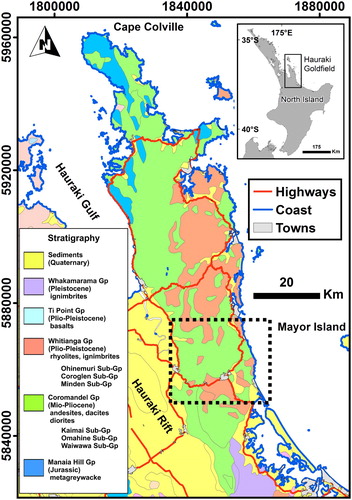
Figure 1. Geological map of the Hauraki Goldfield simplified from Edbrooke et al. (Citation2014). The inset map shows the location of the Hauraki Goldfield on the North Island. The inset stratigraphic column shows the groups and subgroups discussed in the paper. The dashed outline shows the extent of the areas presented in .
This paper reviews the previous compilations of geophysical data over New Zealand epithermal deposits and up-dates them illustrating modern processing and interpretation schemes. The focus is on the Talisman-Waitekauri-Golden Cross trend () because of the availability of extensive geophysical datasets and supporting geological material. However, because of the similar geological setting and topography, the results of the analysis are applicable to most of the Hauraki Goldfield. New processing and interpretation of the geophysical data included in this study helps to understand the signatures of the deposits in some of the newer geophysical datasets.
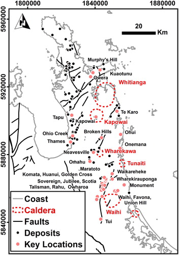
Figure 2. Map of the Hauraki Goldfield showing the extent of the gold and silver mines, mine workings, deposits, and prospects (after , Christie et al. Citation2006). The faults are simplified from Edbrooke et al. (Citation2014). The volcanic centres identified as calderas are from Christie et al. (Citation2006). Deposits and prospects discussed in the text are labelled and identified as key locations with a pink symbol.
Geological setting
The Coromandel Peninsula is composed of Miocene to Pliocene volcanic rocks that unconformably overlie Late Jurassic metagreywacke basement (Skinner Citation1986). The metasedimentary basement rocks crop out in the northwest part of the peninsula (). The volcanic rocks are a sequence of lavas, tuffs, and volcanoclastic sediments. These units are the product of a volcanic arc active from 18 to 2 Ma ago (Adams et al. Citation1994). The volcanism in the Hauraki Goldfield is interpreted to be the precursor to the Taupo Volcanic Zone.
also shows the stratigraphic relationship between the different volcanic units. The early volcanism is dominated by andesitic and dacitic lava (Coromandel Group). In the late Miocene to Pliocene volcanism became more felsic with ignimbrite sheets and rhyolite domes making up the bulk of the Whitianga Group. In this time range, large calderas were active across the peninsula. Prominent calderas shown in include the Whitianga, Kapowai, Wharekawa, Tunaiti, and Waihi centres (Skinner Citation1986; Malengreau et al. Citation2000; Smith et al. Citation2006). In the northeast of the peninsula, and on the offshore islands, more basaltic and andesitic cones (Ti Point Group) developed at the same time as the rhyolitic centres. The Late Pliocene volcanic rocks are in turn covered by Pleistocene ignimbrites of the Wakamarama Group, and recent tephras and sediments (Brathwaite and Christie Citation1996). Volcanism continued to the south and overlaps the onset of volcanism at 2 Ma in the Taupo Volcanic Zone. The intrusive equivalents of the Coromandel and Whitianga Group volcanics are rare in outcrop. The Paritu plutonic suite on Cape Colville is the largest exposure of the intrusive roots of the volcanic centres (Black Citation1972). Smaller outcrops of porphyritic rocks, and broad positive gravity and magnetic anomalies north of Thames, and south of Waihi indicate the presence of other deep seated intrusive bodies (Smith et al. Citation2006).
The peninsula is bounded to the west by the Hauraki Rift (). The eastern edge of the Hauraki Rift is marked by a major crustal-scale normal fault () that has produced uplift of the Hauraki Goldfield and subsidence of the Hauraki graben (Hochstein and Nixon Citation1979; Thrasher Citation1986). The older rocks in the Hauraki Goldfield are cut by a network of northeast to east-northeast trending faults (). A second set of north-northwest striking structures is also present. Reactivation of these deep-seated structures has occurred through-out the late Miocene and early Pliocene (Bahiru et al. Citation2019). Northeast trending topographical and geophysical lineaments, combined with the alignment of epithermal Au-Ag-bearing quartz veins in prospects and mines () indicate a strong structural control on the mineralising fluid flow (Rowland et al. Citation2016). In the southern Hauraki Goldfield, the corridor extends from the Tui mine at Te Aroha, to the Golden Cross mine (Waitekauri Valley), and terminates on the east coast at Ohui (Hay Citation1989; Christie et al. Citation2006). The mining areas of Talisman, Scotia, Komata, and Wharekirauponga also lie within this corridor (). The Waihi, Favona, and Monument deposits lie on a parallel trend that is offset to the southeast of the Waitekauri Valley. A corridor in the central Hauraki Goldfield from Omahu to Te Karo includes the Neavseville, Broken Hills, and Kapowai prospects, while a northern corridor is defined by a series of old workings and prospects from Tapu on the west to Murphy’s Hill on the Kuoatunu Peninsula ().
Christie et al. (Citation2006) illustrate that the age of the mineralisation, associated with the structural trends, is older in the north (11–14 Ma) and younger in the south (5.7 to 7.1 Ma). The Au-Ag mineralisation is concentrated within intense quartz veined zones that exploit the structures and variability in the fracturing patterns of different volcanic lithologies. This quartz veining is present in the deeper roots of the epithermal system, but because of erosion it does crop out in prospects in the western part of the Hauraki Goldfield. Sinters and alteration zones associated with the shallower parts of the systems are more common on the eastern side of the Hauraki Goldfield which has been subjected to less erosion. The deposition of post-mineralisation volcanic rocks and sediments can obscure the epithermal system.
The alteration zones associated with the mineralisation in the Hauraki Goldfield are characteristic of the adularia-sericite epithermal deposits with both lateral and vertical zonation (de Ronde Citation1986; Hedenquist et al. Citation2000; Simpson and Mauk Citation2011). The broad propylitic alteration zone around the hydrothermal system is characterised by the initial breakdown of the igneous minerals to clays (chlorite). As temperature increases closer to the fluid pathways, argillic alteration produces further breakdown of rock forming minerals to illite and sericite. Advanced argillic alteration around the silicic core of the deposit is dominated by a mixture of kaolinite, illite, and smectite. The stockwork and vein systems are brecciated and silicified. There can be a post-mineralisation profile of weathering superimposed on the epithermal signature. Identifying the geophysical characteristics of each of these zones is key to improving the success of geophysics in epithermal exploration (Williams Citation1997).
Geophysical methods
Taking advantage of the available data through the New Zealand Petroleum and Minerals (NZPAM) database, the current paper addresses each of the geophysical methods, building on the previous reviews. Advanced processing software allows us to make more detailed interpretations of the data, and to test their value for exploration. The geophysical methods employed for the exploration of epithermal deposits are not unique to the geology of the deposits or the location. However, some methods have been modified due to different surficial conditions (topography and vegetation), and the availability of geophysical service companies. New Zealand is a challenging environment for both these reasons.
Airborne magnetic surveys and gamma-ray spectrometry
Airborne geophysical surveys provide an opportunity to cover a large area and support geological mapping at a regional and prospect scale. The most common geophysical datasets to collect in airborne surveys are magnetic field and gamma-ray spectrometry. Airborne magnetic data are measured using a total field magnetometer either slung below a helicopter in a ‘bird’ or mounted on the helicopter or plane on a boom or ‘stinger’. Modern surveys utilise high precision proton, caesium vapour, or optical pumping magnetometers to acquire data at a sample rate of 1 ms and a sensitivity of less than 0.01 nT. Processing of airborne magnetic data includes removal of noise caused by the aircraft, removal of natural field changes due to solar activity, levelling of flight line data using tie lines, and gridding to generate a smoothly varying field. The total field is sensitive to changes in the induced and remanent magnetisation of the rocks below the aircraft. Magnetic susceptibility (k) measurements on outcrops and drillcore are often available to help interpret and model the magnetic field data. Igneous and metamorphic rocks are generally more magnetic than sedimentary rocks due to higher concentrations of magnetic minerals such as magnetite (Dentith and Mudge Citation2014). Mafic rocks are generally more magnetic than felsic volcanic rocks. In epithermal and geothermal regions alteration can result in a decrease in both susceptibility and remanence due to the breakdown of magnetite to non-magnetic minerals such as pyrite.
Aerial gamma-ray surveys, also referred to as radiometric surveys or spectrometry, are generally collected simultaneously with the magnetic data. The sensor comprises a NaI detector, a spectrometer, and an acquisition system. The detector is mounted on the aircraft or helicopter facing downwards to capture natural gamma-rays emitted from the soil and rock immediately below. The decay spectra are measured over a range of energy levels (0.4–6.0 MeV) and peaks are identified that correspond to the decay of potassium (40K), uranium (U) via 214Bi, and thorium via 208Tl. The data are corrected for other gamma-ray sources such as cosmic rays, radon, and background emissions from the aircraft. The data are integrated over the sample time, corrected for geometry and terrain clearance, and presented as counts-per-second (cps) for the entire spectra (Total) and the individual elements (K, U, Th). If the sensor has been calibrated over a test pad then the data can be converted to concentrations of the elements (Minty et al. Citation2009). Gamma-rays are absorbed rapidly in the subsurface so the data are sensitive to the top 0.5 m of the regolith and are affected by moisture content and vegetation cover. The data (cps, ppm or %) are gridded at the same resolution as the magnetic data, and are presented as total counts, individual elements, ratios of the three, or a ternary plot. Potassium makes up approximately 2.4% of the earth’s crust. The concentration is higher in minerals such as potassic-feldspars and micas, so felsic rocks produce stronger K values than mafic rocks. Clays such as illite and smectite also produce strong K anomalies. Uranium and thorium (3 and 12 ppm respectively) are far less abundant than potassium. They are also more abundant in silica rich rocks than in mafic rocks. Uranium is very mobile and is rapidly leached out with weathering and alteration (Dickson and Scott Citation1997).
Airborne magnetic data have been acquired over most of the Hauraki Goldfield in numerous surveys (Table S1). In 1977 and 1978, Amoco Minerals NZ Ltd., flew the first low level helicopter surveys, draped at a constant clearance over the terrain. Both surveys were acquired with a line spacing of 500 m, a terrain clearance of 150 m, significantly improving the resolution of the magnetic map at that time (Couper and Lawton Citation1978; Moore and Lawton Citation1979). These data formed the basis for most of the exploration for epithermal and porphyry deposits from the mid 1970s to the mid 2000s. The data are available in digital format either from the raw profile data or from digitised contours (Rabone Citation1991; Stagpoole et al. Citation2001). Between 1987 and 1994, a range of smaller surveys were flown by different operators to provide more detail at a line spacing of 150 m. Table S1 identifies each data set that has been used to create the merged magnetic maps used in this study (). Most of these data are available in digital format and have been compiled by several authors as part of government initiatives to stimulate exploration (Stagpoole et al. Citation2001; Vidanovich Citation2003). The surveys flown since 1987 included gamma-ray spectrometer data. Regional analysis of a merged set of airborne magnetic and radiometric data from the southern part of the Hauraki Goldfield has been undertaken by Locke et al. (Citation2006) and Morrell et al. (Citation2011). Newmont and its joint venture partners have reflown large areas of the Hauraki Goldfield at 150 m spacing between 2005 and 2009 (e.g. Van Woerden Citation2006). Some of these data are now available in the public domain. The western side of the Hauraki Goldfield has been covered by modern data sets both for mineral exploration (Waihi Gold Company Citation2006) and petroleum exploration of the Hauraki Rift (Mule and Stenning Citation2010). The area over Waihi Beach and offshore to Mayor Island has been flown () as part of an ironsands exploration programme (Loftus and Rogerson Citation2011). Finally, the area over Whitianga was flown at low resolution as part of a research project at Auckland University (Malengreau et al. Citation2000).
Figure 3. Airborne magnetic map of the Hauraki Goldfield and the Hauraki Plains. Shading is from the northeast. The total magnetic intensity (TMI) has been scaled using histogram equalisation between the minimum and maximum values indicated on the colour bar. The dashed outline shows the extent of the areas presented in . Annotations a, b, and c are discussed in the text.
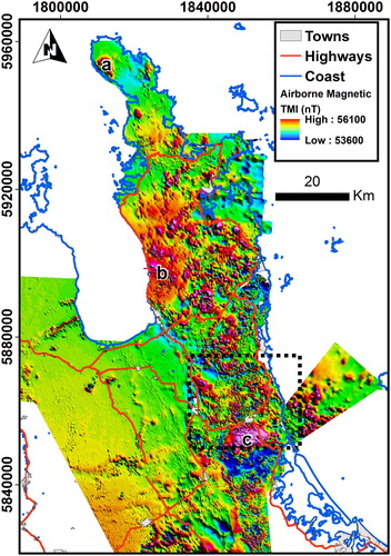
The airborne data from twelve surveys over the southern Hauraki Goldfield have been merged into a single grid using stitching routines that minimise the misfit between adjacent grids. Where multiple datasets exist, the most recent data or the data with the highest resolution, have been given priority. The merged dataset has a grid spacing of 25 m. Standard airborne magnetic processing techniques have been applied to the merged grid to make geological interpretation of the data easier. Reduction to pole (RTP) is a Fast Fourier Transform based filter designed to centralise the anomalies over the causative body. In surveys close to the equator or in extreme topography, where the magnetic body could be above the sensor in a draped survey, the transform can produce spurious results. In New Zealand the RTP filter performs well due to the moderately high geomagnetic latitude. We have chosen to use the present day orientation of the field (inclination −63o, declination 20o east) rather than the average over the age of the rocks (8–2 Ma). Strong remanent magnetic responses may not be correctly rotated by the RTP filter. The resulting grid is shown in A. The airborne data have been collected in drape mode with the helicopter maintaining a uniform ground clearance that varies between 50 and 150 m (see Table S1). The variation in topography across the area is large (0–600 m) so in some valleys the presence of magnetic sources in the outcropping volcanic rocks beside or above the magnetometer may produce anomalous results in the reduction to pole and other filtered products.
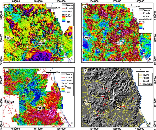
Figure 4. Geophysical data over the southern Hauraki Goldfield. A, Magnetic field reduced to pole. B, Analytic signal of the Reduced to Pole total field. Locations labelled a–h are discussed in the text. C, Gamma-ray spectrometry data presented as total counts. D, Shaded topography. The dashed line shows the extents of . The locations of epithermal deposits are shown as red symbols (Christie et al. Citation2006).
The radiometric data have also been compiled into a single grid (C). However, some data are not available in digital format, leaving gaps in the coverage. The original processing used to reduce the older data sets to K, Th, and U counts is poorly documented so levelling the data is less quantitative than for airborne magnetic data (Minty Citation2000). A technique of histogram matching has been applied to merge overlapping grids and balance the signal amplitudes (Cowan and Cooper Citation2008). The most reliable and valuable maps for geological mapping in epithermal gold exploration areas are the total counts and the element ratio of thorium to potassium (Shives et al. Citation2000; Minty Citation2011; Morrell et al. Citation2011). The grid of total counts presented as counts per second (C) has been scaled to the most modern dataset in the region (Dataset 23 in Table S1).
The regional magnetic anomaly pattern has been interpreted by Rowland et al. (Citation2016) and Bahiru et al. (Citation2019) in terms of lineaments and structures that define crustal scale blocks. Magnetic anomalies of note at the regional scale include the positive anomaly over the Paritu plutonic suite on Cape Colville (labelled a in ), a broad region of positive anomalies north of Thames (labelled b in ), and the high amplitude anomaly south of Waihi (labelled c in ). The area north of Thames, may be underlaid by laterally extensive deep seated intrusive rocks given the presence of narrow porphyry dykes and the Ohio Creek porphyry Cu prospect in the region (). Malengreau et al. (Citation2000) and Rabone (Citation1991) interpreted the broad positive gravity anomaly in this area to indicate the presence of a deep-seated dense intrusive body. The magnetic anomaly over the northern Kaimai ranges (labelled c in ) has been attributed to a similar deep-seated intrusive (Couper and Lawton Citation1978) but Smith et al. (Citation2006) attributed the anomaly to outcropping highly magnetic andesites.
Many authors have noted that the airborne magnetic data over epithermal deposits indicate zones of widespread demagnetisation likely associated with alteration (Irvine and Smith Citation1990; Hoschke and Sexton Citation2005; Morrell et al. Citation2011). Similar trends are seen in modern geothermal systems in the Taupo Volcanic Zone (Allis Citation1990). While the pattern is visible in the total field anomaly map (A), the zones of reduced magnetic intensity can be emphasised using several filtering approaches. The vertical gradient and the analytic signal (Roest et al. Citation1992) produce the greatest contrast between high magnetic relief unaltered rocks, and the subdued alteration zones. B shows the analytic signal over the southern Hauraki Goldfield. The combination of reduction to pole, the calculation of the derivatives, and the artificial sun-shading exaggerates some of the noise that remains from the levelling of the data and merging the grids (B). But despite this noise, the areas of low magnetisation are obvious.
At a regional scale the Waitekauri Valley, between Waihi and Paeroa, is seen as a large zone of subdued magnetic response (Morrell et al. Citation2011) that covers the historical mining areas (A). The Empire/Golden Cross epithermal system lies at the northeastern edge of the region of reduced magnetic intensity (labelled d in B). By incorporating the small high-resolution airborne survey that was flown before the development of the open pit mine (Sharp Citation1987) into the regional compilation, a clearer image is available of the Golden Cross exploration area (A). Ground magnetic data, collected over the prospects at 25 m station spacing and 100 m line spacing, did not add any more detail to the airborne survey (Collins Citation1989; Hay Citation1989). Zones of subdued magnetic field highlighted in B in the vicinity of the Waitekauri Valley, correspond to the Au-Ag mineralisation occurrences of Sovereign/Jubilee/Scotia (b), Komata (c), Golden Cross (d), Waiharakeke/Waitete (e), Mataura (f), Wharekirauponga (g), and Maratoto (h). The current mining lease around Waihi and Favona lies within another zone of intense demagnetisation (Locke et al. Citation2006; Morrell et al. Citation2011). A similar localised zone (labelled a in B) was mapped around the Talisman Mine by Harris et al. (Citation2005).
The process of demagnetisation is attributed to the alteration of magnetite in the host volcanic rocks, to non-magnetic minerals such as pyrite and sphene by mineralising fluids (de Ronde Citation1986). This alteration starts in the distal propylitic zone and is most intense in the proximal advanced argillic and sericitic zone, often producing a ringed pattern to the anomaly. Potassium metasomatism is another alteration process that produces the breakdown of primary minerals (plagioclase and ferromagnesian minerals) to produce adularia and illite (Booden et al. Citation2011). This alteration can have an additional effect on the magnetic field with the reduction in magnetic susceptibility due to the breakdown of mafic minerals.
Variations in the host rock magnetic properties will depend on the mafic and oxide mineralogy with andesites and dacites having higher susceptibilities than more felsic rhyolites (Turner et al. Citation2017). In volcanic regions such as the Hauraki Goldfield, Natural Remanent Magnetisation (NRM) is likely to be more important than susceptibility in determining the variations in the magnetic signature. Periods of reversed polarity of the earth’s magnetic field, recorded in the Miocene and Pliocene volcanics in the Hauraki Goldfield could produce pronounced magnetic lows, even in volcanic rocks with no indication of alteration. An example of rhyolites, with hand samples having high susceptibility, but lying within a low magnetic anomaly has been reported at the Ohui prospect (Irvine and Smith Citation1990). Overprinting of the original NRM due to changes in the magnetic field over time (Viscous Remanent Magnetisation) can be seen in some of the andesites, further complicating the resulting magnetic anomaly. The key characteristic of the alteration by epithermal fluids is the reduction in magnitude of the magnetic field, both positive and negative, hence the success of the analytic signal in mapping the extent of magnetite destruction. A more thorough discussion on the magnetic properties of rocks from the Hauraki Goldfield is found in Table S2 in the supplemental material.
The airborne gamma-ray spectrometer data support the interpretation of alteration as a contributor to the reduction of magnetic signal over large areas with significant mineralisation (Morrell et al. Citation2011). Variations in total counts and individual counts (K, Th, U) can be dominated by lithological controls in the region, as felsic rocks represented by rhyolites and ignimbrites of the Whitianga Group, have higher concentrations of these elements than the more mafic andesites and dacites of the Coromandel Group (Booden et al. Citation2011). These authors report that the ratio of thorium to potassium is relatively constant for the unaltered volcanic rocks so variations in the mapped Th/K values indicate areas of significant potassium enrichment due to alteration and metasomatism. Morrell et al. (Citation2011) identified anomalous zones of high potassium counts over the quartz vein systems of Waihi, Empire/Golden Cross, Wharekirauponga, Komata, Sovereign, and Jubilee. They also noted the effect of elevated counts over the rhyolites in the Komata and Maratoto area that masked the epithermal system. The supplemental material includes a summary of geochemical data from volcanic rocks in the region showing the variation in K2O (Table S2). The airborne gamma-ray survey (C) shows that the region east of the Waitekauri Valley and west of Waihi is marked by low total counts corresponding to unaltered andesites and dacites (labelled e and f in C). The use of the 1987 data over Golden Cross helps remove the effects of the open pit mine and tailings pond seen in previous interpretations (Morrell et al. Citation2011). Wharekirauponga (labelled g) and Talisman/Karangahake (labelled a) have very strong total count anomalies. In the case of the Talisman Mine the response is due to alteration (Harris et al. Citation2005) but at Wharekirauponga the anomalies could indicate the presence of rhyolitic host rocks. D shows a shaded-relief image of the terrain highlighting the strong northeast structural grain, and the alignment of deposits. The area over the Upper Waitekauri Valley, outlined by the dashed line, is discussed in more detail in .
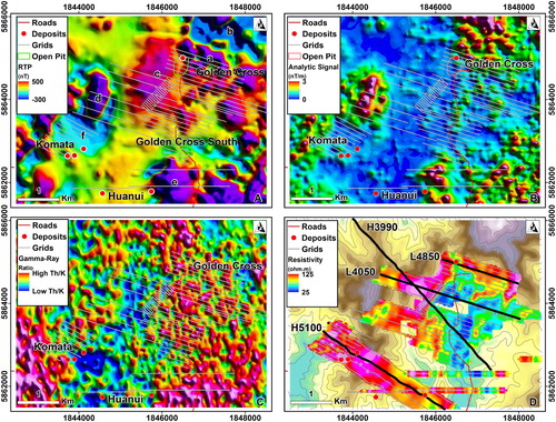
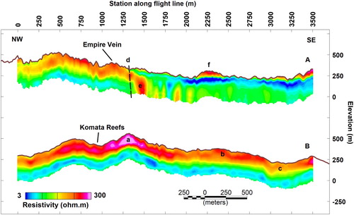
Figure 5. Geophysical data over the Upper Waitekauri Valley The survey lines are for the Empire, Golden Cross, Golden Cross South, Komata Reefs, Huanui and Laneway ground geophysics grids. The surface locations of the Golden Cross, Komata, and Huanui Au-Ag deposits are shown. Features labelled a–f are discussed in the text. A, Detail of Reduced To Pole (RTP) magnetic field. B, The analytic signal of the RTP field. C, Th/K ratio from the gamma-ray spectrometer survey. D, The resistivity data from gradient array and shallow dipole-dipole surveys. The 50 m depth slice from the HoistEM data is also shown. The resistivity data are on a logarithmic scale from 25(blue) to 56 (yellow) to 125 ohm m (red). The backdrop is a contour map of the topography high-lighting the ridgelines in brown and the valleys in light green. The four lines labelled on the map are shown as cross-sections in .
Resistivity methods
In order to plan drilling programmes, ground-based geophysical surveys and surface sampling on a grid are essential. The steep topography and thick forest cover in the Hauraki Goldfield requires survey grid lines, as well as access roads, to be cut by line crews increasing the cost of ground geophysics. Resistivity has been widely used in the area to help select epithermal exploration targets. During the 1970s and early 1980s, dipole-dipole resistivity/induced polarisation (IP) surveys were the most popular technique (Locke Citation1983). Electrical resistivity is a rock property that is sensitive to the degree of weathering, alteration, and fluid content. The electrical resistivity of a rock is a function of its porosity, pore fluid chemistry, matrix clay content, and the presence of connected low resistivity minerals (e.g. graphite). Induced polarisation effects such as chargeability will increase both with higher clay content and the presence of disseminated sulphide minerals. In some cases, large bodies of ore (e.g. copper-zinc and massive sulphide deposits) form a continuous low resistivity anomaly, which is readily detected using any resistivity method if bounded by contrasting higher resistivity formations. However, epithermal Au-Ag mineralisation is typically disseminated throughout a zone of quartz veins and is therefore usually associated with high rather than low resistivity. Flanking formations of high porosity and intense clay alteration often provide a contrasting low resistivity background. Electrical methods were very valuable in the Hishikari case study, where early use of Schlumberger soundings identified a layering of high resistivity unaltered andesites over low resistivity altered volcanics. Later dipole-dipole induced polarisation surveys were able to detect the steeply dipping zone of porous breccia and quartz veining containing hot mineralised geothermal fluids, and the highest concentrations of Au-Ag (Okada Citation2000). In the following section we describe the various resistivity methods used and their strengths. Dentith and Mudge (Citation2014) describe the advantages of the various array types. More detail on the resistivity of the rocks from the Hauraki Goldfield is provided in the supplemental material (Table S2).
Dipole-dipole resistivity
The depth of investigation of the early dipole-dipole surveys was limited by the electrode spacing and number of offsets recorded. A typical 50 m dipole with offsets up to six dipole depths (n = 6) is unlikely to detect anomalies deeper than 100 m. Increasing the dipole length to 100 m increased the signal and depth of investigation but unfortunately reduced the lateral sensitivity (Jensen and Slater Citation1984). The data were noisy due to the high contact resistances of the volcanic rocks and low transmitter power (Locke Citation1983). Cables laid out on narrow cut-lines over clay-rich soils were subject to electromagnetic coupling, masking the subtle induced polarisation responses. Despite the limitations of the resistivity/IP method, Locke (Citation1983) and Allis (Citation1990) demonstrated that the derived pseudosections were useful in revealing the contrasts between resistive unaltered andesite (200–300 ohm m), altered ignimbrites (10–40 ohm m), and low resistivity highly altered zones (5–10 ohm m).
Gradient array resistivity
Collecting resistivity/IP data on lines out to offsets of n = 6 is time consuming and requires complicated operations to move potential and current electrodes, and cables. Collecting dipole-dipole data with dipoles smaller than 50 m and line spacings less than 100 m is too expensive for most exploration companies, so alternate methods have been deployed to get a better spatial coverage of the resistivity structure. The gradient array method employs a single set of current electrodes, one at each end of the exploration grid (Bennie and Bromley Citation1995). The receiving dipole is moved along the survey lines to map out the apparent resistivity. The receiver electrode spacing was 20–50 m, and the line spacing was 50–100 m. The gradient array configuration proved to be a very valuable method for mapping the lateral extent of low resistivity zones (propylitic and argillic alteration), and the highly resistive narrow quartz vein systems associated with the gold mineralisation. In most cases the outcropping vein systems could be mapped into areas where they were obscured by weathering or a thin layer of post-mineralisation volcanic cover. However, the depth of investigation for gradient array surveys is even less than dipole-dipole. Gradient array surveys were undertaken across most prospects in the Hauraki Goldfield. The Waitekauri Valley contains a wide coverage of gradient array data including the Scotia, Sovereign, Jubilee, Komata, Golden Cross South, Golden Cross, and Empire grids. These data are presented in the more detailed analysis of the Waitekauri Valley.
Pole-dipole and bipole-dipole resistivity
The pole-dipole array is a compromise between the dipole-dipole and the gradient array. The pole-dipole array is sensitive to a larger rock volume than the dipole-dipole array, reducing the effects of the steep terrain. With only one current electrode to move, the surveying is faster than for the dipole-dipole array. In an early application of a pole-dipole survey at the Talisman Mine, electrode spacings of 20 m were found to give good resolution, and measured resistivities ranged from 15 to 4500 ohm m, with higher values coinciding with zones of intense silicification and stockwork veining (Apthorpe et al. Citation1986). Often these highs were also on ridges making interpretation more difficult because of possible topographic distortions. Argillic altered rhyolites provided a very conductive shallow host formation. Data obtained using a 60 m dipole spacing, for deeper probing, was not as useful because of reduced resolution. More recent pole-dipole surveys have been undertaken in the Waitekauri Valleys utilising systems that have higher powered transmitters and more sensitive receivers so dipole offsets of up to n = 8 and 9 are possible, greatly increasing the depth of investigation (Ranford Citation2017). Bipole-dipole surveys utilise a remote transmitter bipole to generate an electric field across the survey grid and then small receiver dipoles to map out the lateral variation of the field (Bromley et al. Citation1996). The investigation depth is a function of the offset from the transmitting bipole. Measuring orthogonal components of the electric field at each receiver site enables mapping of local three-dimensional perturbations of the current around resistive bodies. A tensor version of the bipole-dipole method, employing three transmitter bipole orientations, was used together with conventional Schlumberger array traversing and sounding to investigate the deeper resistivity structure of the Waihi basin and surrounding region (Bromley and Brathwaite Citation1991).
In all of these direct current methods, the lines of electric current in the earth are affected by steep topography. Current density increases in narrow valleys reducing the apparent resistivity, and decreases over steep hills resulting in an increase in apparent resistivity. Modern two and three-dimensional inversions provide a more effective tool for correcting for topographic effects in resistivity data (Oldenburg and Li Citation1994).
Ground electomagnetic surveys
Ground-based electromagnetic (EM) methods are commonly used in exploration for low resistivity ore deposits such as massive sulphides. The secondary magnetic fields produced from the slow decay of electric currents in low resistivity rocks are easily detected using induction loops and coils. However, for resistive anomalies, such as quartz veins, the signals are weak and often masked by low resistivity near-surface layers. Methods that inject electric current into the ground, and measure both electric and magnetic fields over the targets are best suited for the types of resistivity variations found in epithermal and porphyry deposits.
Controlled-source audiomagnetotellurics (CSAMT) utilises a grounded dipole transmitter positioned 4–8 km away from the exploration grid, and a receiver that measures orthogonal components of the electric field, and the magnetic field with a dipole and an induction coil respectively (Zonge and Hughes Citation1991). The method determines the resistivity structure at different depths by measuring the electromagnetic response at a range of frequencies typically from 8192 Hz (shallow depth of investigation) to 4 Hz (larger volume of investigation). The apparent resistivity is determined from the ratio of the measured electric and magnetic fields resulting from the inductive effect of the transmitted horizontal magnetic fields. The depth of investigation, known as ‘skin-depth’ is also dependent on the resistivity of the subsurface so in resistive volcanic terrains the system can detect targets down to depths of 500 m. The CSAMT response is complicated by three-dimensional effects where the resistivity structure between the transmitter and the survey line interferes with the signal at the receiver. At high frequencies the transmitter overprint is small and the data are able to be interpreted as simple one or two-dimensional models on the profiles. Even in a simple layered earth the electromagnetic signal from the transmitter, at low frequencies and small offsets, is often non-planar and the data need to be processed to include the distorting effect of the direct current from the transmitter dipole (Zonge and Hughes Citation1991). The overprint is termed the ‘near-field’ effect. There is a transition between these two end-members at mid-frequencies that can lead to erroneous interpretations of the data. Despite these complications, early success with CSAMT surveys over the Hishikari deposit led to the wide spread use of the technique in Japan (Okada Citation2000).
Controlled-source audiomagnetotellurics surveys have been conducted on at least twelve Hauraki Goldfield epithermal deposits and prospects including Golden Cross, Ohio Creek, Ohui, Owera, Murphy’s Hill, Union Hill, Wharekirauponga, Waikaraheke, Waihi, Favona, Golden Cross South, Broken Hills, and Rahu (see ). Initial CSAMT tests between 1987 and 1990 utilised early generations of the CSAMT equipment with a limited number of receiver dipoles (Zonge and Hughes Citation1991). Collecting one or two stations per set-up made surveying times long. The development of more modern systems with up to eight receiver channels allowed survey lines to be completed more rapidly making the survey cost effective compared to resistivity surveys. As with dipole-dipole and gradient array surveys, the lateral resolution was limited by the electric field dipole length. Most surveys employed 40 or 50 m dipole lengths, but some test surveys reduced the spacing to 20 m (McOnie Citation1989) resulting in better detection of narrow resistive targets.
One criticism of the method is the ambiguous nature of resistivity anomalies in the CSAMT sections. There are several examples in exploration reports from the Hauraki Goldfield where the CSAMT response was interpreted as a narrow resistive target at depth consistent with quartz veining, but the drilling failed to find any distinct cause of the resistive anomaly. At Owera and Murphy’s Hill, Rabone (Citation1991) reported that a strong resistive anomaly beneath the outcropping Murphy’s Vein, was found to be caused by a block of unaltered massive andesite, flanked by intense smectite and sericite clay alteration. At Ohui () there have been several rounds of CSAMT surveys followed by drilling. The ‘Box’ prospect is identified on several lines as a zone of high resistivity at depth that is juxtaposed against a laterally extensive low resistivity boundary (Irvine and Smith Citation1990). Several boreholes (e.g. DDH-7 and DDH-12) have been drilled into the resistive zone (Austpac Citation1988). The drilling showed that the intensity of quartz veining (10–20 veins/m) was increasing with depth indicating that the target corresponded to stockworks at the upper levels of an epithermal system. Rhyolitic dykes were also encountered in some of the drill-holes and may explain the higher resistivities. A resistivity logging tool was run in DDH-12, revealing a complex pattern of alternating high and low resistivity layers within an unaltered andesite (Figure S2). The resistivity log showed that the CSAMT method was more sensitive to the broad increase in bulk resistivity with depth, rather than a discrete zone.
The lack of vertical resolution, combined with the complexities caused by three-dimensional effects led to the CSAMT method being used less frequently in New Zealand between 1995 and 2005. More recently, with the advent of instruments with better signal to noise and more channels, the use of CSAMT has increased. Collecting CSAMT on tighter line spacing, in the Waihi area, has led to a greater understanding of the lateral extents of the vein systems at depth between the Martha deposit and Favona deposit (Torckler et al. Citation2016). Extensive CSAMT surveying has also been undertaken by Glass Earth in the Taupo Volcanic Zone over epithermal deposits (Henderson et al. Citation2016). Both Heritage Mining (Tilley and Atkinson Citation2011) and Evolution Mining (Beach and Hobbins Citation2016) have used CSAMT as their primary geophysical exploration tool over the Rahu (Karangahake) and Puhipuhi (Northland) prospects, respectively. More modern inversion methods have reduced the miss-positioning of resistive targets but only the integration of CSAMT models with other geophysical data can reduce the ambiguity in interpretation.
The magnetotelluric (MT) method is a deeper imaging version of CSAMT. The natural electromagnetic signals originating from the Earth’s ionosphere, magnetosphere, and lightning strikes in equatorial regions, produce a uniform pattern of source fields at a range of frequencies from 1000 Hz to 0.001 Hz. The frequency range for MT can be extended to 10,000 Hz with the use of high-frequency induction coils, but variations in natural signal strength in several frequency bands often make CSAMT more efficient. The advantage of the MT method is there is no need to deploy a transmitter, and data are not affected by near-field responses. The main disadvantage is that each site requires up to 24 h to acquire sufficient signal across the entire frequency range. In resistive volcanic terrains the frequency band is suited for imaging in the 1 km to 50 km depth range. The MT method has been adopted as the primary exploration tool in active geothermal exploration, where much lower resistivities are encountered, and the geothermal field is deeper and covers a wider area (Bertrand et al. Citation2013). Magnetotellurics have been used in the Hauraki Goldfield to map the deeper structure of the Tertiary calderas (Malengreau et al. Citation2000), and to image the faults that bound the epithermal systems in the Waitekauri Valley (Walter et al. Citation2012). Combining regional MT data with prospect scale CSAMT and resistivity/IP surveys offers an opportunity to image the shallow structure and identify the deep-seated faults that are the conduits for the mineralised fluids.
Airborne electromagnetics
There are no reported examples of ground-based time or frequency domain inductive electromagnetic surveys in the Hauraki Goldfield. However, Newmont Waihi Gold undertook a large time-domain airborne electromagnetic survey in 2007. They utilised a proprietary system (HoistEM) developed by Normandy in Australia and integrated into the Newmont geophysics programme with the merger of the two companies in 2002 (Eaton et al. Citation2013). HoistEM utilises a hexagonal transmitter loop with an area of 375 m2. The loop is towed 30–40 m below the helicopter, at an altitude of between 40 and 75 m above the terrain. The receiver is mounted within the transmitter loop, and the system is powered by a generator mounted on the helicopter skids (Boyd Citation2004). The current is increased logarithmically in the loop until it reaches a peak of 320 Amperes. The current is then shut off rapidly to produce a transient signal in the subsurface. The waveform is repeated in the opposite polarity and the signal repeats at a base frequency of 25 Hz. Given the low ground speeds possible with a helicopter, the signal can be stacked many times and still provide a sample interval of 5–10 m on the ground. Eddy currents induced in the ground produce a signal that is detected by the receiver during the ‘offtime’. The data are recorded continuously and processed into 27 discrete channels for analysis and modelling (Vrbancich and Fullagar Citation2007). Rapid inversion schemes allow a one-dimensional resistivity model to be computed at each station and a cross-section constructed along the flight path. Gridding data from closely spaced lines for a constant depth produces maps of resistivity at comparable scales to the airborne magnetic and gamma-ray spectrometer data.
Helicopter electromagnetic systems had been used in 1978 to map the presence of conductive alteration zones below the resistive unaltered volcanics in Kyushu (Japan) leading to the discovery of the Hishikari deposit (Johnson and Fujita Citation1985). The ability of helicopter mounted systems to cover large areas, staying within 100 m of the ground, and flying at low speeds on closely spaced lines makes the technique very attractive for initial screening of tenements. Airborne electromagnetic systems have limitations due to shallow depth of investigation (50–300 m) and insensitivity to narrow resistive zones. However, the mapping of the low-resistivity alteration zones, especially buried below 10–50 of unaltered cover is very practical with airborne electromagnetic surveys.
Gravity and seismic
Gravity surveys are sensitive to lateral changes in rock density. Physical and chemical processes that occur in the formation of epithermal deposits such as precipitation of hydrothermal minerals can reduce the porosity, resulting in an increase in bulk density. Positive gravity anomalies of up to 10 mGals are observed over epithermal deposits, depending on the extent of alteration, and the density contrast with the host rocks (Allis Citation1990). Regional structures may play a larger role in determining the gravity anomalies. The Hishakari deposit is marked by a positive anomaly, interpreted to be due to uplifted basement rocks. The Pajingo deposit in Queensland has a 4–5 mGal positive anomaly that defines the lateral extent of the host volcanic system (Hoschke and Sexton Citation2005). The Waihi deposit, despite having low density surficial deposits, is marked by a strong positive anomaly (Morrell et al. Citation2011) interpreted to be a deeper intrusive or uplifted basement. The Karangahake deposit is also associated with a broad positive gravity anomaly (Harris et al. Citation2005).
Other volcanic systems associated with epithermal mineralisation have negative anomalies. The felsic calderas in the Hauraki Goldfield can be mapped using the outlines of the residual negative anomalies (Malengreau et al. Citation2000). More complex calderas that have experienced the collapse of the bounding faults, described by Smith et al. (Citation2006) as trap-door calderas, also have negative anomalies. The prominent negative anomaly south of Waihi is modelled as a graben that has been infilled with lower density sediments and volcaniclastics. The deposits in the Waitekauri Valley (Rahu, Scotia, and Golden Cross) have subtle negative anomalies. Intense leaching of host rocks by acid hydrothermal fluids, or extensive micro-fracturing, could increase the effective porosity, and therefore decrease the density, causing a gravity low over the affected formation (Locke and de Ronde Citation1987). Gravity surveying faces several challenges. First, the data must be collected at sufficiently close station spacing (<50 m) with low noise levels (<0.1 mGal) to resolve the lateral density changes. Second, the residual anomaly needs to be clearly identified from regional trends. Third, independent constraints need to be placed on the rock densities or the geometry to reduce ambiguity when modelling the data. Density data have been compiled from a range of published studies and are provided in the supplemental material (Table S2). No additional modelling of gravity data is included in this study, but Bahiru et al. (Citation2019) utilise the gravity anomalies for regional analysis of the crustal scale structures.
Seismic velocity is another rock property that could be used to determine the porosity of the subsurface rocks. The seismic reflection method relies on a combination of density and velocity contrasts between units to generate reflections. The technique has not been employed extensively in volcanic terrains due to the steep dips of the bounding faults, the complexity of the near-surface geology, and the lack of continuous layering at seismic scales in the volcanic rocks. A test seismic line was collected in the Golden Valley region east of Waihi to map the depth extent of volcaniclastic sediments in a small graben (Barber et al. Citation2009). The line was not acquired using standard seismic reflection methods so it is difficult to determine the reliability of the data. A test using modern acquisition systems, a larger seismic source, and more sophisticated processing needs to be conducted in the Hauraki Goldfield to determine if seismic reflection methods will be valuable. Seismic processing techniques have developed significantly in the last ten years and large three-dimensional seismic surveys are being undertaken over established mines to identify new orebodies to extend the life of the mine (e.g. Malehmir et al. Citation2017) but the costs are high and the targets need to be focussed.
Waitekauri Valley case study
The Waitekauri Valley is an ideal location to review the range of geophysical responses of epithermal deposits as it contains a large number of prospects and deposits. The Golden Cross deposit lies in the upper Waitekauri Valley. It was discovered in 1882, and has a history of gold production from shallow workings in the Golden Cross, Empire, and Taranaki Hippo veins (1895–1900), renewed mining in the 1920s (de Ronde Citation1986), and then the development of an open pit and subsequent underground mine between 1991 and 1998 (Mauk and Purvis Citation2006). White et al. (Citation1995) and Mauk and Purvis (Citation2006) attributed reserves of 2.3 Mt of ore to the stockwork (2.8 g/t Au), and 3 Mt to the vein zone with higher grades of 7.2 g/t Au and 17 g/t Ag. Other Au-Ag bearing areas in the vicinity of upper Waitekauri Valley are the Komata deposit which produced 17 t of Au-Ag bullion between 1891 and 1938, and smaller workings at Huanui stream, and Grace Darling (Braithwaite and Christie Citation1996).
Brathwaite and Christie (Citation1996) show that the Coromandel Group in the area is represented by the dacites and andesites of the Waiwawa sub-group (), that have been tilted during faulting and subjected to alteration and weathering. The Whakamoehau Andesite (Omahine sub-group) post-dates the mineralisation and crops out on all major topographic highs and partially covers the Waitekauri Valley. Rhyolites of the Maratoto Formation (Whitianga Group) occur in isolated areas on the western side of the valley.
summarises the geophysical data collected over the Upper Waitekauri Valley and surrounds. The lines that comprise the various ground exploration grids are shown in A to help reference the location of the airborne anomalies. At a local scale the reduced to pole magnetic field shown in A has a strong positive anomaly (labelled a) that coincides with the southern flank of the Coromandel Range at the head of the valley. This area is dominated by the post-mineralisation Whakamoehau Andesite. The intense low to the north (labelled b) is the dipole response from a strongly magnetic volcanic unit outcropping near the Wharekirauponga deposit to the north. The character of the magnetic anomaly over the Whakamoehau Andesite is controlled by the thickness of flows and the rugged topography on the flanks of Mt Whakamoehau. The analytic signal defines the southern edges of the Whakamoehau Andesites (B).
A zone of moderate magnetic amplitudes (labelled c in A) extends over the western part of the Golden Cross grid, and is related to the older andesites and dacites of the Waipupu Formation. This block lies in the footwall of the Western Boundary Fault (Begbie et al. Citation2007). These rocks have undergone some degree of alteration and produce a low amplitude analytic signal. The gamma-ray spectrometer data have been processed to produce the element ratio of Th/K. The bulk of the merged data are from the 1987 BP survey and the 1994 Coeur survey (Table S1) and have not been calibrated. Each component has been normalised before computing the ratio. A scalar of 2 is applied to the numerator (thorium) to further emphasise the enrichment of potassium in the negative anomalies (Minty Citation2011). C shows that the potassium is enriched relative to thorium over the western part of the Golden Cross grid (refer to area labelled c in A).
Southwest of the Golden Cross grid lies a large magnetic high (labelled d in A), with a similar sized anomaly in the analytic signal. The Th/K ratios are typical of unaltered rocks and the topography, shown in D, confirms that the area is a ridge line, and is composed of young post-mineralisation andesite (Brathwaite and Christie Citation1996). The Komata Reefs deposit lies in a zone of low magnetic intensity (labelled f in A) produced by the superposition of the low surrounding the strong magnetic high over the unaltered andesites, and a zone of demagnetisation. The analytic signal is depressed over the Komata grid, but the very low Th/K ratios are found to the southeast of the outcropping quartz veins. The Komata deposit is hosted in more felsic rocks of the Maratoto Rhyolite, so the potassium enrichment is a combination of host lithology and alteration. In the southeast part of the study area, the total magnetic field is high, the analytic signal is strong, and the Th/K ratio is high, indicating more outcrops of the post mineralisation andesite flows. The road along the Waitekauri Valley to the Golden Cross mine, cuts through the middle of the Golden Cross South grid. The analytic signal is variable, and the Th/K ratios show patches of potassium enrichment and unaltered rock. Zones of illite/smectite alteration have been mapped in the streams that drain into the Waitekauri River (de Ronde Citation1986).
The resistivity data from the gradient array and shallow dipole-dipole surveys (Locke Citation1983; Cyprus Minerals NZ Ltd Citation1987; Bennie and Bromley Citation1995) are shown in D. In order to balance the response from the different methods, the resistivity is presented on a logarithmic scale and the colour bar is stretched using histogram equalisation. The zones of high resistivity (>125 ohm m) correspond to the outcropping quartz vein zones at Empire, Golden Cross, and Komata Reefs. The unaltered andesites on the ridge tops are also highly resistive. The southern edge of the Whakamoehau Andesite is clearly seen cutting diagonally across the Golden Cross grid. These data pre-date the mining and the construction of the tailings pond. The footwall of the Western Boundary Fault (labelled c in A) is seen as a block of moderately high resistivity rock. This block extends to the west over the Komata north grid. The resistivities under the Komata Reefs grid (refer to area labelled f in A) are generally high, in part due to the smaller dipole spacing (20 m) being more sensitive to quartz rich areas.
A set of four HoistEM lines from McConnochie (Citation2008) that cross the valley have been processed as part of this project, using one-dimensional inversion (Farquharson and Oldenburg Citation1993), to produce a resistivity slice at 50 m depth below ground surface (D). The data agree well with the resistivities from the dipole-dipole data at Komata Reefs, Huanui Creek, and from across the centre of the Waitekauri Valley. The eastern end of the pole-dipole lines, collected across the Golden Cross road (Ranford Citation2017), reveal a narrow low resistivity zone (see area labelled e in A) juxtaposed against the resistive andesites on the eastern flanks of the valley (D). The low resistivity zone widens to the north across the Golden Cross South gradient array survey. Resistivities less than 25 ohm.m indicate a high degree of alteration along the eastern side of the access road. The area to the west of the Golden Cross South grid has moderate resistivities indicating a thin cover of weathered rock over partially altered or unaltered volcanics.
Mapping resistivity anomalies in the top 10–20 m is valuable for targeting deeper investigations. The dipole-dipole resistivity data collected over the Golden Cross prospect (Cyprus Minerals NZ Citation1987) have been reprocessed using a two-dimensional resistivity inversion algorithm (Oldenburg and Li Citation1994). D shows the locations of two lines discussed in this study. shows line 4850N which was one of the main sections used to evaluate the Golden Cross deposit prior to mining (Collins Citation1989). The data were collected with 100 m electrode spacing and extended to offsets of six dipoles. Both resistivity and induced polarisation measurements were made but only the apparent resistivity have been modelled in this study (A). The inversion scheme proceeds to generate the smoothest two-dimensional model that fits the observations within an error tolerance. The best model is shown in C and its response (B) is a good match with the observations. The section has been interpreted (D) using a combination of existing geological sections (Begbie et al. Citation2007; Christie et al. Citation2011).
Figure 6. Line 4850N IP/Resistivity survey. A, Pseudosection of observed apparent resistivity, dipole spacing is 100 m, dipole offsets from 1 to 6, number of measurements = 123, resistivity scale is logarithmic. B, Calculated model response, apparent resistivity. C, Resistivity model. D, Interpretation, locations labelled a–d are discussed in the text. The orange dashed line is the potential extent of alteration.
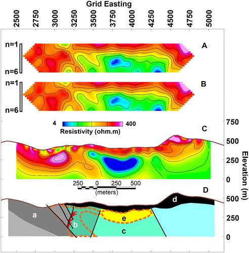
The Waitekauri stream at station 2800E corresponds to the surface expression of the Western Boundary Fault. The Waipupu Formation in the footwall (labelled a in D) of the Western Boundary Fault is resistive at depth. Within the highly altered stockwork zone of the Golden Cross deposit, the resistivity is variable (>500 ohm m to <50 ohm m). An earlier dipole-dipole survey completed by Amoco with 50 m electrode spacing showed very rapidly changing apparent resistivities through this zone (Locke Citation1983). The intensely silicified and gold-rich zone of the Empire Vein system is located at station 3200E (labelled b in D). The Empire Vein lies at the boundary between conductive rocks in the east, and resistive rocks to the west. The actual vein system is likely to be too thin to be resolved by the dipole-dipole data.
The Waiharekeke Formation dacites are mapped by drillhole data to the east of the Empire Vein (Christie et al. Citation2011). These rocks are moderately resistive (see c in D). The Whakamoehau Andesite (labelled d) is seen as a layer of high-resistivity (>100 ohm m) extending across the section from the east (Allis Citation1990). The very low resistivities (<10 ohm m) below the Whakamoehau Andesites (see e in D) could represent lacustrine volcaniclastic sediments or a thin highly-weathered unconformity.
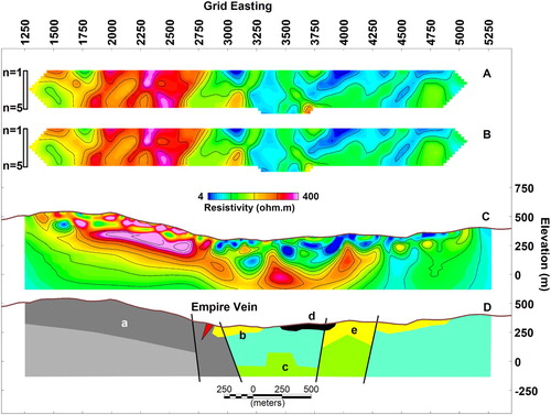
The resistivity sections further south (e.g. 4050N in ) extend well to the west onto the Waipupu Formation and show the footwall of the Western Boundary Fault to have variable resistvities at the surface but to be uniformly resistive at depths of 50–100 m. Resistivities decrease at 200–300 m depth which is interpreted to indicate a contact within the Waipupu Formation (labelled a in D). The southern part of the Empire Vein is visible as a small resistivity anomaly at station 2900E. East of the baseline (3000E) the surficial layer has low resistivity and is mapped as altered volcanics (b and e in D). Line 4050N extends eastward across the valley and confirms the lateral extent of the altered or weathered rocks. A thin outcrop of resistive Whakamoehau Andesite may be present in the centre of the line (location d in D). The anomalously high resistivity at depth in the centre of the valley (location c in D) could be a block of unaltered volcanic rocks, or a zone of quartz veins. This target is at the limit of the depth of investigation for the 100 m spaced dipole-dipole data.
Figure 7. Line 4050N IP/Resistivity survey. A, Pseudosection of observed apparent resistivity, dipole spacing is 100 m, dipole offsets from 1 to 6, number of measurements = 186, resistivity scale is logarithmic. B, Calculated model response, apparent resistivity. C, Resistivity model. D, Interpretation, Features labelled a–e are discussed in the text.
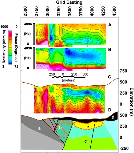
Lines 4850N and 5050N were used for a test CSAMT survey by Zonge Engineering in 1986 (Collins Citation1989; Zonge and Hughes Citation1991). The CSAMT data from line 4850N () show similar resistivity anomalies to that seen in the dipole-dipole resistivity (A). The apparent resistivity and impedance phase data are typically presented as pseudosections with frequency displayed on the vertical axis indicating increasing depth (A and 8B respectively). In layered structures the apparent resistivity will indicate the rough trends in the variations of true resistivity with depth but is biased by the very near-surface resistivity. This effect is referred to as ‘static shift’ and is very common in complex geological environments such as the Hauraki Goldfield. The impedance phase is defined as the phase lead of the electric field (Ey) over the magnetic field (Hx) and is expressed in degrees (°). Over a uniform geology the phase is a constant (45°) independent of the bulk resistivity. The phase is not affected by static shift. On line 4850N, both the apparent resistivity and the phase show the presence of a shallow resistive zone overlying a conductive zone. The phase decreases below 45° at 64 Hz indicating the presence of a deeper resistive zone. The anomalously low phases (<15°) at the base of the pseudosection indicate the transmitter near-field zone has more of an influence on the data west of station 3300 (B). The inversion results shown in Zonge and Hughes (Citation1991) and Dentith and Mudge (Citation2014) are reproduced in C to illustrate the greater depth of investigation of the CSAMT dataset compared to the dipole-dipole resistivity data (C). Between stations 2900 and 3200E the data are complicated by the large lateral resistivity contrasts produced by the stockworks and deeper vein systems. The pattern of electric current flow is likely to be highly three-dimensional in this area so one-dimensional modelling is not adequate. D shows the same geological section from the dipole-dipole line (D), but it has been extended to 750 m depth. The Waipupu Formation is seen in the footwall of the Western Boundary Fault (see a in D). The Empire Vein and alteration zones (b in D) lie within the complex resistivity anomaly at 3200E. The deep resistive zone (c in D) is likely to be unaltered Waiharakeke Formation dacite, and the shallow resistive zone (d in D) is the Whakamoehau Andesite. The low resistivity zone that dominates the dipole-dipole section (C) is shown as a thinner zone (e in D) in the CSAMT data.
Figure 8. Line 4850N CSAMT survey across the Golden Cross deposit. The data were collected prior to the development of the open pit and underground mine. A, Apparent resistivity pseudeosection. B, Phase pseudosection. C, Smooth 1D inversion models. The model section has been reproduced from Zonge and Hughes (Citation1991). The resistivity scale is logarithmic and the phase scale is linear. D, Interpretation of the cross-section based on drilling and mine development. The dashed orange line shows the alteration halo around the mineralised vein system. Features labelled a–e are discussed in the text.
The HoistEM data on Line 5100 and 3990 (D) are shown as cross-sections in . The inversion scheme used to process these data (Farquharson and Oldenburg Citation1993) produces a smoothly varying resistivity model for each transient electromagnetic (TEM) sounding. The airborne data have been resampled to 20 m station intervals. Line 5100 (B) extends from west of the Komata deposit to the southern Waitekauri Valley. The section shows anomalously high resistivities in the vicinity of the Komata Reefs and over the top of the ridge (labelled a in B). The resistivity decreases to the east along the line but increases again at station 2300E (b in B). The map of near-surface resistivity (D) shows that this resistive zone on the western edge of the Waitekauri Valley is also present on the ground resistivity lines. At the eastern end of the line in B, the resistivity drops significantly across the centre of the Waitekauri Valley (c in B). The line to the north (3990) is shown in A. This section crosses from west of the Empire grid to the centre of the Northern Waitekauri Valley. The resistivity model compares well with the dipole-dipole section 4050N (C). The fault to the east of the Empire Vein is shown at location d in the section (A). The deep resistive anomaly (labelled e in A) is also present in the ground resistivity data. Low resistivities are mapped across the Waitekauri Valley with a thin resistive surficial layer capping the section between stations 2150 and 2500 m (identified as f in A). This resistive zone could be a thin outcrop of Whakamoehau Andesite.
Figure 9. Inversion models from HoistEM survey. A, Line 3990 across the northern Waitekauri Valley. B, HoistEM survey line 5100 across the central Waitekauri Valley. The models have been generated using a smooth 1D inversion of the HoistEM soundings. The resistivity values are on a logarithmic scale. Locations a–f are discussed in the text.
Despite the lack of detail compared to the dipole-dipole and CSAMT sections, the HoistEM sections do show the main resistivity features of the Waitekauri Valley and flanking hills. The cost of acquiring airborne EM data is significantly lower than collecting ground-based resistivity data, on a per line-kilometre basis.
Discussion and conclusion
Epithermal Au-Ag deposits can be successfully targeted with geophysics at a range of scales. Airborne magnetic and gamma-ray spectrometer surveys can identify the zone of propylitic and argillic alteration associated with the flux of geothermal fluids through the shallow levels of the deposit. The destruction of magnetite and the enrichment of potassium in the alteration zones can be mapped in derived products such as the analytic signal of the magnetic field, and the Th/K elemental ratio in the gamma-ray data. When the host rocks are dominantly andesites and dacites, and the alteration extends to the surface, the pattern is quite diagnostic. More felsic host rocks such as rhyolites produce a more complex pattern, and a cover of unaltered sediments or andesites makes detection a challenge. Electrical resistivity is the most reliable tool for mapping both the low resistivity alterations zones and the high resistivity quartz veined roots of the mineralised systems. Ground-based resistivity methods such as gradient array, dipole-dipole, and CSAMT methods are able to be modelled to further improve the accuracy of the interpretation. Airborne electromagnetic methods provide a stepping stone between the reconnaissance mapping of the magnetics and gamma-ray spectrometer surveys, and the ground geophysics. However, the inductive airborne electromagnetic methods are not able to identify thin quartz-rich zones either at surface or at depth. They do have the advantage of being able to penetrate 30–50 m of cover and detect low resistivity alteration zones. Gravity, magnetotellurics and possibly seismic reflection surveys have a role to play in mapping the regional scale structures that control the distribution of feeder systems to the shallow epithermal deposits. Glass Earth undertook an innovative exploration programme in the Taupo Volcanic Zone using airborne gravity gradiometry, airborne magnetics, electrical resistivity, and CSAMT to identify the areal extent of the epithermal systems (Henderson et al. Citation2016). They combined all available geophysical data into a multi-parameter evaluation that identified the edges of the deposits. Patterns of anomalies were identified and interpretations made based on the lateral and estimated depth extents of the anomalies.
Drone based surveying techniques are developing rapidly and commercial systems are available for magnetic surveying. They offer the advantage of being closer to the ground than helicopter surveys producing an anomaly map that rivals a ground-based survey in detail. Drone based photogrammetry and remote-sensing is becoming more standard, resulting in very detailed topographic maps at the prospect scale. Developments in hyperspectral imaging offers possibilities for mapping alteration zones directly or through the influence of the soils on vegetation.
Controlled-Source Audiomagnetotelluric surveys (CSAMT) have given exploration teams the best models of the subsurface with which to plan drilling programmes. Advances in processing include two-dimensional modelling of profiles using the full frequency range acquired. Three-dimensional inversion of CSAMT data is a practical option in the Waihi and Waitekauri camps given the number of profiles (Torckler et al. Citation2016). The density of magnetotelluric (MT) soundings in the Hauraki Goldfield is not sufficient to identify regional structures. Additional MT stations would extend the depth of investigation of the CSAMT data to 1–5 km, and potentially identify the roots of the epithermal systems.
Improvements in resistivity surveying, including the use of GPS time-synchronised distributed receiver systems that allow longer offsets (n = 10–12), could dramatically increase the ability to look deeper and identify subtle induced polarisation responses. Similarly, three-dimensional resistivity surveying and modelling will reduce some of the miss-positioning of resistivity anomalies and increase the chances of intersecting resistive units with exploration boreholes. Proprietary three-dimensional resistivity acquisition techniques such as E-Scan have increased the density of data collected over some prospects in the Taupo Volcanic Zone (Henderson et al. Citation2016) but the sensitivity of resistivity methods to narrow resistive bodies is still uncertain. The deflection of electric current around vertical quartz veins observed by Bromley and Funnell (Citation1990) at the Martha mine and Golden Cross, strongly suggests that a direct current method that can measure the amplitude and direction of the electric current flow in map view has a chance of identifying narrow bodies at depth. Airborne methods such as ZTEM and AFMAG are designed to detect current channelling and deflection by observing the resulting vertical magnetic fields. The airborne technique ZTEM has been a very successful tool for epithermal Au-Ag exploration in North and South America (e.g. Hubert et al. Citation2016). To date, ZTEM has not been tested in New Zealand.
Additional rock properties data such as magnetisation measurements on oriented samples, and petrophysical data from borehole logs are key to improving the modelling and interpretation of geophysical data.
Figure S2. Borehole geophysical logs and geological interpretation from Ohui prospect well DDH-12.
Download MS Word (258 KB)Supplemental Material: SF3
Download MS Word (19.7 KB)Figure S1. Distribution of individual surveys that are used to build the airborne magnetic and gamma-ray spectrometry maps. The numbers refer to the surveys listed in Table S1.
Download MS Word (261.7 KB)Table S1: Airborne geophysical surveys over the Hauraki Goldfield
Download MS Word (15.9 KB)Table S2: Rock Properties
Download MS Word (15.7 KB)Acknowledgements
This manuscript has benefitted from the input of members of the Gold Exploration Models (GEM) team including Tony Christie, Engda Bahiru, Jennifer Eccles, and Julie Rowland. Vaughan Stagpoole at GNS Science is acknowledged for discussions on the geophysical datasets available. Data have been derived mostly from the New Zealand Petroleum and Minerals online exploration database with some additional data from Newmont/OceanaGold. Lorrance Torckler is thanked for allowing access to some of those data. Coeur Mining are thanked for allowing the publication of data over the Golden Cross Mine and Golden Cross South prospect. The project is funded by Ministry of Business Innovation and Employment (MBIE) contestable grant GEM- Gold Exploration Models. Software used in the modelling has been provided under academic licences by Geosoft and the UBC Geophysical Inversion Facility. Reviews by Fabio Caratori Tontini and Michael Roach have improved the quality of the paper.
Disclosure statement
No potential conflict of interest was reported by the authors.
ORCID
Richard L. Kellett http://orcid.org/0000-0001-6215-8610
Chris J. Bromley http://orcid.org/0000-0002-3342-0584
Additional information
Funding
Related Research Data
References
- Adams CJ, Graham IJ, Seward D, Skinner DNB. 1994. Geochronological and geochemical evolution of late Cenozoic volcanism in the Coromandel Peninsula, New Zealand. New Zealand Journal of Geology and Geophysics. 37:359–379. doi: 10.1080/00288306.1994.9514626
- Allis RG. 1990. Geophysical anomalies over epithermal systems. Journal of Geochemical Exploration. 36:339–374. doi: 10.1016/0375-6742(90)90060-N
- Apthorpe KA, Rosenhain AM, McAlister LM. 1986. ML 32039 Mt. Karangahake, Coromandel Peninsula: report on exploration for the period August 1985 to March 1986, Freeport Australia Minerals Ltd. NZP&M, Ministry of Business, Innovation and Employment, Wellington, unpublished open-file mineral report MR517.
- Austpac. 1988. Final report on PL 31874, Ohui, Coromandel. Austpac Gold Exploration NZ Ltd. NZP&M, Ministry of Business, Innovation and Employment, Wellington, unpublished open-file mineral report MR591.
- Bahiru EA, Rowland JV, Eccles JD, Kellett RL. 2019. Regional crustal-scale structural control on epithermal deposits within the Hauraki Goldfield, Coromandel Volcanic Zone, New Zealand: insight from integrated geological and aeromagnetic structural patterns. New Zealand Journal of Geology and Geophysics, this volume.
- Barber AJW, Stevens MR, Atkinson PR. 2009. Technical Report on Golden Valley Project. NZP&M, Ministry of Business, Innovation and Employment, Wellington, unpublished open-file mineral report MR4495.
- Beach V, Hobbins JM. 2016. Puhipuhi – a high-level epithermal gold–silver prospect in northland. In: Christie AB, editor. Mineral deposits of New Zealand — exploration and research. Melbourne: Australasian Institute of Mining and Metallurgy Monograph. 31; p. 219–224.
- Begbie MJ, Spörli KB, Mauk JL. 2007. Structural evolution of the Golden Cross epithermal Au-Ag deposit, New Zealand. Economic Geology. 102:873–892. doi: 10.2113/gsecongeo.102.5.873
- Bennie SL, Bromley CJ. 1995. Golden Cross South gradient array resistivity survey Waitekauri Valley, Waihi. Coeur Gold New Zealand. IGNS confidential client report 72540C.10.
- Bertrand EA, Caldwell TG, Hill GJ, Bennie SL, Soengkono S. 2013. Magnetotelluric imaging of the Ohaaki geothermal system, New Zealand: implications for locating basement permeability. Journal of Volcanology and Geothermal Research. 268:36–45. doi: 10.1016/j.jvolgeores.2013.10.010
- Black PM. 1972. Hornfelses from Paritu, Coromandel County. Journal of the Royal Society of New Zealand. 2(2):211–228. doi: 10.1080/03036758.1972.10429375
- Booden MA, Mauk JL, Simpson MP. 2011. Quantifying metasomatism in epithermal Au-Ag deposits: a case study from the Waitekauri area, New Zealand. Economic Geology. 106:999–1030. doi: 10.2113/econgeo.106.6.999
- Boyd GW. 2004. HoisTEM – a new airborne electromagnetic system: PACRIM proceedings. Adelaide. Australasian Institute of Mining and Metallurgy, Publication Series 5/2004, 211–218.
- Brathwaite RL, Christie AB. 1996. Geology of the Waihi area: part sheets T13 and U13, scale 1:50,000. Lower Hutt: Institute of Geological and Nuclear Sciences of New Zealand geological map 21.
- Bromley CJ. 1993. A strategy for geophysical exploration of New Zealand epithermal systems. Proceedings 27th Annual Conference, Wellington: AusIMM, New Zealand Branch. p. 109–120.
- Bromley CJ, Funnell RH. 1990. In-situ resistivity measurement of veins in epithermal goldmines near Waihi. In: Harvey CC, Browne PRL, Freeston DH and Scott GL, editors. Proceedings of the 12th New Zealand Geothermal Workshop, Auckland. p. 233–236.
- Bromley CJ, Brathwaite RL. 1991. Waihi Basin structure in light of recent geophysical surveys. Proceedings of the 25th Annual Conference 1991, AusIMM, New Zealand Branch, Waihi. p. 225–238.
- Bromley CJ, Bennie SL, Graham DJ. 1996. Golden Cross South CSAMT resistivity survey Waitekauri Valley, Waihi. Coeur Gold New Zealand. IGNS confidential client report 72633C.
- Christie AB, editor. 2016. Mineral deposits of New Zealand — exploration and research. Carlton: Australasian Institute of Mining and Metallurgy monograph 31.
- Christie AB, Brathwaite RL, editors. 2006. Geology and exploration of New Zealand mineral deposits. Parkville: Australasian Institute of Mining and Metallurgy monograph 25.
- Christie AB, Brathwaite RL, Mauk JL, Simpson MP. 2006. Hauraki Goldfield — regional exploration databases and prospectivity studies. In: Christie AB, Brathwaite RL, editor. Geology and exploration of New Zealand mineral deposits. Melbourne: Australasian Institute of Mining and Metallurgy monograph 25; p. 73–84.
- Christie AB, Thomas J, McOnie A, Carver R. 2011. 3D modelling and geochemistry of epithermal Au-Ag mineralization at Golden Cross based on legacy mining and exploration data. GNS Science Report 2011/06. 35p.
- Collins S. 1989. Case history of geophysical surveys over the Golden Cross gold silver deposit. Exploration Geophysics. 20:75–79. doi: 10.1071/EG989075
- Couper PG, Lawton DC. 1978. Final report on exploration licence 33051, Southern Coromandel Peninsula, New Zealand, Amoco Minerals NZ Ltd. NZP&M, Ministry of Business, Innovation and Employment, Wellington, unpublished open-file mineral report MR350.
- Cowan DR, Cooper GRJ. 2008. Merging radiometric grids using histogram matching. Computers & Geosciences. 34:291–298. doi: 10.1016/j.cageo.2007.05.012
- Cyprus Minerals NZ Ltd. 1987. Golden Cross mining project, Mining Licence Application. Cyprus Minerals NZ Ltd. NZP&M, Ministry of Business, Innovation and Employment, Wellington, unpublished open-file mineral report MR552.
- de Ronde CEJ. 1986. The Golden Cross gold-silver deposit. In: Henley RW, Hedenquist JW, Roberts PJ, editors. Guide to the active epithermal (geothermal) systems and precious metal deposits of New Zealand. Monograph Series on Mineral Deposits No 26. Berlin-Stuttgart: Gebrueder Borntraeger; p. 165–183.
- Dentith M, Mudge ST. 2014. Geophysics for the mineral exploration geoscientist. Cambridge: Cambridge University Press. 450 p.
- Dickson BL, Scott KM. 1997. Interpretation of aerial gamma-ray surveys – adding the geochemical factors. AGSO Journal of Australian Geology and Geophysics. 17:187–200.
- Eaton PA, Anderson RG, Queen SV, Nilsson BY, Lauritsen E, Barnett CT, Olm M, Mitchell S. 2013. Helicopter time-domain electromagnetics — Newmont and the NEWTEM experience. Geophysics. 78:W45–W56. doi: 10.1190/geo2012-0472.1
- Edbrooke SW, Forsyth PJ, Jongens R. (compilers). 2014. Geology Map of New Zealand. Scale 1:1 000 000, digital vector data. Lower Hutt: GNS Science.
- Farquharson CG, Oldenburg DW. 1993. Inversion of time-domain electromagnetic data for a horizontally layered earth. Geophysical Journal International. 114:433–442. doi: 10.1111/j.1365-246X.1993.tb06977.x
- Harris MC, Cassidy J, Locke CA, Mauk JL, Stevens M, Vidanovich P. 2005. Geophysical characteristics of the Karangahake epithermal deposit Hauraki Goldfield, New Zealand. New ZealandMinerals Conference. Auckland New Zealand, Proceedings. p. 115–124.
- Hay KR. 1989. Exploration case history of the Golden Cross project, Waihi, New Zealand. In: Kear D, editor. Mineral deposits of New Zealand. Melbourne: Australasian Institute of Mining and Metallurgy Monograph 13; p. 67–72.
- Hedenquist JW, Arribas AR, Gonzalez-Urien E. 2000. Exploration for epithermal gold deposits. Reviews in Economic Geology. 13:245–277.
- Henderson SM, Christie AB, Soengkono S, Henderson D, Howie K, Smith B, Coote J, Cahill JF. 2016. Glass earth staged exploration for epithermal gold–silver deposits in the Southern Hauraki Goldfield and Taupo Volcanic Zone, North Island, 2003–2013. In: Christie AB, editor. Mineral deposits of New Zealand — exploration and research. Melbourne: Australasian Institute of Mining and Metallurgy monograph 31; p. 237–246.
- Henley RW, Ellis AJ. 1983. Geothermal systems ancient and modern: a geochemical review. Earth-Science Reviews. 19:1–50. doi: 10.1016/0012-8252(83)90075-2
- Hochstein MP, Nixon IM. 1979. Geophysical study of the Hauraki Depression, North Island, New Zealand. Journal of Geology and Geophysics. 22:1–19. doi: 10.1080/00288306.1979.10422550
- Hoschke T, Sexton M. 2005. Geophysical exploration for epithermal gold deposits at Pajingo, North Queensland, Australia. Exploration Geophysics. 36:401–406. doi: 10.1071/EG05401
- Hubert J, Lee BM, Liu L, Unsworth MJ, Richards JP, Abbassi B, Cheng LZ, Oldenburg DW, Legault JM, Rebagliati M. 2016. Three-dimensional imaging of a Ag-Au-rich epithermal system in British Columbia, Canada, using airborne z-axis tipper electromagnetic and ground-based magnetotelluric data. Geophysics. 81:B1–B12. doi: 10.1190/geo2015-0230.1
- Irvine RJ, Smith MJ. 1990. Geophysical exploration for epithermal gold deposits. Journal of Geochemical Exploration. 36:375–412. doi: 10.1016/0375-6742(90)90061-E
- Izawa E, Urashima Y, Ibaraki K, Suzuki R, Yokoyama T, Kawasaki K, Koga A, Taguchi S. 1990. The Hishikari gold deposit: high-grade epithermal veins in Quaternary volcanics of southern Kyushu, Japan. Journal of Geochemical Exploration. 36:1–56. doi: 10.1016/0375-6742(90)90050-K
- Jensen K, Slater J. 1984. PL 31557 Renoulfs New Find Work Progress Report for BP Oil NZ Ltd, NZP&M, Ministry of Business, Innovation and Employment, Wellington, unpublished open-file mineral report MR776.
- Johnson IM, Fujita M. 1985. The Hishikari gold deposit: an airborne EM discovery. Canadian Institute of Mining Bulletin. 78:876.
- Locke CA. 1983. Geophysical investigations of Golden Cross Prospect, Waitekauri Valley, May 1983, Amoco Minerals NZ Ltd. NZP&M, Ministry of Business, Innovation and Employment, Wellington, unpublished open-file mineral report MR453.
- Locke CA, de Ronde CEJ. 1987. Delineation of gold-bearing hydrothermally altered rocks using gravity data — A New Zealand example. Geoexploration. 24:471–481. doi: 10.1016/0016-7142(87)90016-0
- Locke CA, Johnson SA, Cassidy J, Mauk JL. 1999. Geophysical exploration of the Puhipuhi epithermal area, Northland, New Zealand. Journal of Geochemical Exploration. 65:91–109. doi: 10.1016/S0375-6742(98)00067-3
- Locke CA, Morrell AE, Cassidy J, Smith N. 2006. Magnetic and gravity methods in the exploration of epithermal deposits in the Coromandel Peninsula, Hauraki Goldfield. In: Christie AB, Brathwaite RL, editor. Geology and exploration of New Zealand mineral deposits. Melbourne: Australasian Institute of Mining and Metallurgy monograph 25; p. 95–100.
- Loftus N, Rogerson P. 2011. Desktop discovery, seismic review and aeromagnetic survey results for EP52474. Pacific Offshore Mining Limited. NZP&M, Ministry of Business, Innovation and Employment, Wellington, unpublished open-file mineral report MR4847.
- Malehmir A, Bellefleur G, Koivisto EA, Juhlin C. 2017. Pros and cons of 2D vs 3D seismic mineral exploration surveys. First Break. 35:49–55.
- Malengreau B, Skinner DNB, Bromley CJ, Black P. 2000. Geophysical characterisation of large silicic volcanic structures in the Coromandel Peninsula, New Zealand. New Zealand Journal of Geology and Geophysics. 43:171–186. doi: 10.1080/00288306.2000.9514879
- Mauk JL, Purvis A. 2006. The Golden Cross epithermal Au-Ag deposit, Hauraki Goldfield, New Zealand. In: Christie AB, Brathwaite RL, editor. Geology and exploration of New Zealand mineral deposits. Carlton: Australasian Institute of Mining and Metallurgy monograph 25; p. 151–156.
- McConnochie MR. 2008. Report on EP40679 to 26th October 2008. Surrendered portion. Waitekauri Valley South. Newmont Waihi Gold. NZP&M, Ministry of Business, Innovation and Employment, Wellington, unpublished open-file mineral report MR4433.
- McOnie A. 1989. Union Hill prospect Waihi detailed CSAMT geophysical survey, April 1989. Mineral Resourves NZ Ltd. NZP&M, Ministry of Business, Innovation and Employment, Wellington, unpublished open-file mineral report MR2377.
- Minty B. 2000. Automatic merging of gridded airborne gamma-ray spectrometric surveys. Exploration Geophysics. 31:47–51. doi: 10.1071/EG00047
- Minty B, Franklin R, Milligan P, Richardson M, Wilford J. 2009. The radiometric map of Australia. Exploration Geophysics. 40:325–333. doi: 10.1071/EG09025
- Minty B. 2011. Short note: on the use of radioelement ratios to enhance gamma-ray spectrometric data. Exploration Geophysics. 42:116–120. doi: 10.1071/EG10011
- Moore CR, Lawton DC. 1979. Final report on exploration license 33055 Eastern Coromandel Peninsula, New Zealand – Project NZ-76-2. Amoco Minerals NZ Ltd. NZP&M, Ministry of Business, Innovation and Employment, Wellington, unpublished open-file mineral report MR367.
- Morrell AE, Locke CA, Cassidy J, Mauk JL. 2011. Geophysical characteristics of adularia-sericite epithermal gold-silver deposits in the Waihi-Waitekauri region, New Zealand. Economic Geology. 106:1031–1041. doi: 10.2113/econgeo.106.6.1031
- Mule S, Stenning L. 2010. North Waikato and West Coast airborne magnetic and radiometric geophysical survey. Chartwell MZ Pty Ltd. NZP&M, Ministry of Business, Innovation and Employment, Wellington, unpublished open-file petroleum report PR4135.
- Okada K. 2000. Geophysical exploration at Hishikari gold mine, Kagoshima, Japan. The Leading Edge. 19:744–750. doi: 10.1190/1.1438708
- Oldenburg DW, Li Y. 1994. Inversion of induced polarization data. Geophysics. 59:1327–1341. doi: 10.1190/1.1443692
- Rabone SDC. 1991. Residual total force magnetic anomaly map, Coromandel region. Scale 1:100 000. Report M183 NZ Geological Survey, DSIR (IGNS).
- Ranford C. 2017. Partial relinquishment report MEP 53469 (Waitekauri). Laneway Resources Ltd. NZP&M, Ministry of Business, Innovation and Employment, Wellington, unpublished open-file mineral report MR5452.
- Roest WR, Verhoef J, Pilkington M. 1992. Magnetic interpretation using the 3-D analytic signal. Geophysics. 57:116–125. doi: 10.1190/1.1443174
- Rowland JV, Bahiru EA, Schofield M, Hamilton A, Pickle R, de P Zuquim M, Eccles JD. 2016. Tectonic and structural controls on late Miocene-to-recent epithermal gold–silver mineralisation, Northern New Zealand. In: Christie AB, editor. Mineral deposits of New Zealand — exploration and research. Melbourne: Australasian Institute of Mining and Metallurgy Monograph 31; p. 247–259.
- Sharp B. 1987. 1987 Aeromagnetic Survey Report, Central North Island and Coromandel Peninsula (Tairua area), BP Oil NZ Ltd. NZP&M, Ministry of Business, Innovation and Employment, Wellington, unpublished open-file mineral report MR659.
- Shives RBK, Charbonneau W, Ford KL. 2000. The detection of potassic alteration by gamma-ray spectrometry—recognition of alteration related to mineralization. Geophysics. 65:2001–2011. doi: 10.1190/1.1444884
- Sillitoe RH. 1995. Exploration and discovery of base- and precious-metal deposits in the circum-Pacific region during the last 25 years. Resource Geology special issue 19. 119p.
- Sillitoe RH. 2010. Exploration and discovery of base- and precious-metal deposits in the circum-Pacific region — a 2010 perspective. Resource Geology special issue 22. 139p.
- Simpson MP, Mauk JL. 2011. Hydrothermal alteration and veins at epithermal Au-Ag deposits and prospects of the Waitekauri area, Hauraki Goldfield, New Zealand. Economic Geology. 106:945–973. doi: 10.2113/econgeo.106.6.945
- Skinner DNB. 1986. Neogene volcanism of the Hauraki volcanic region. Royal Society of New Zealand Bulletin. 23:20–47.
- Smith N, Cassidy J, Locke CA, Mauk JL, Christie AB. 2006. The role of regional-scale faults in controlling a trapdoor caldera, Coromandel Peninsula, New Zealand. Journal of Volcanology and Geothermal Research. 149:312–328. doi: 10.1016/j.jvolgeores.2005.09.005
- Stagpoole VM, Christie AB, Henrys SA, Woodward DJ. 2001. Aeromagnetic map of the Coromandel region: total force anomalies. Lower Hutt: Institute of Geological and Nuclear Science. Geophysical Map 14.
- Thrasher GP. 1986. Basement structure and sediment thickness beneath the continental shelf of the Hauraki Gulf and offshore Coromandel region, New Zealand. Journal of Geology and Geophysics. 29:41–50. doi: 10.1080/00288306.1986.10427521
- Tilley D, Atkinson P. 2011. Technical report for EP 40117 – Rahu. NZP&M, Ministry of Business, Innovation and Employment, Wellington, unpublished open-file mineral report MR4836.
- Torckler LK, Hobbins JM, Christie AB. 2016. Mining and exploration of the epithermal gold–silver deposits at Waihi, Hauraki Goldfield. In: Christie AB, editor. Mineral deposits of New Zealand — exploration and research. Melbourne: Australasian Institute of Mining and Metallurgy monograph 31; p. 303–312.
- Turner GM, Kellett RL, Caratori Tontini F, Stagpoole VM, Christie AB. 2017. Magnetc Properties of Rocks from the Southern Coromandel. Lower Hutt (NZ): GNS Science Report 2017/25. 26 p.
- Van Woerden T. 2006. Exploration of Kaimai PP 39298 Hauraki Goldfield NZ Business, Innovation and Employment, Wellington, unpublished open-file mineral report MR4205.
- Vidanovich P. 2003. Aeromagnetic Geophysics Compilation 1950–2001. NZP&M, Ministry of Business, Innovation and Employment, Wellington, unpublished open-file mineral report MR4260.
- Vrbancich J, Fullagar PK. 2007. Improved seawater depth determination using corrected helicopter time-domain electromagnetic data. Geophysical Prospecting. 55:407–420. doi: 10.1111/j.1365-2478.2007.00602.x
- Waihi Gold Company Ltd. 2006. Exploration of Kerepehi PP39301 Hauraki Goldfield NZ from 6th December 2005 until 31st December 2006. Waihi Gold Company Ltd. NZP&M, Ministry of Business, Innovation and Employment, Wellington, unpublished open-file mineral report MR4209.
- Walter C, Wameyo P, Shalev E, Malin PE. 2012. Electromagnetic study of mineralised and active fracture zones in the southern Hauraki Goldfield, New Zealand. Proceedings of the 46th annual conference, New Zealand Branch of the Australian Institute of Mining and Metallurgy. p. 445–453.
- Webster SS, Henley RW. 1989. Application of high resolution airborne geophysics to epithermal gold exploration in northeast Queensland and Coromandel, New Zealand. Exploration Geophysics. 20:99–102. doi: 10.1071/EG989099
- White NC, Leake MJ, McCaughey SN, Parris BW. 1995. Epithermal gold deposits of the southwest Pacific. Journal of Geochemical Exploration. 54:87–136. doi: 10.1016/0375-6742(95)00027-6
- Williams PK. 1997. Towards a multidisciplinary integrated exploration process for gold discovery. In: Gubins AG, editor. Proceedings of exploration 97: fourth decennial international conference on mineral exploration. Toronto: Prospectors and Developers Association of Canada; p. 1015–1028.
- Zonge KL, Hughes LJ. 1991. Controlled-source audio-frequency magnetotellurics. Electromagnetic Methods in Applied Geophysics, Society of Exploration Geophysicists. 2:713–810. doi: 10.1190/1.9781560802686.ch9