
Abstract
In 2017 the Transient Reactor Test (TREAT) Facility was restarted after having been placed in a standby state in 1994. The TREAT reactor’s restart has since enabled the progressive development of new nuclear technologies within the United States that previously were outsourced to other countries. While the reactor’s restart was a large feat worthy of recognition, the experimental use of its characteristics has required further development of an in-pile experimental infrastructure sufficient to support programmatic needs. This hardware has taken the form of capsule designs (compact and elongated) as well as loop concepts representing the phenomena of interest for a subset of the separate effects tests desired for each respective testing campaign. The transient testing program has been a large integrated effort that aligns with the U.S. Department of Energy’s current needs. This study complements those programmatic elements by developing, fabricating, and demonstrating a full-scale flowing water loop in an out-of-pile environment. The goal of this effort is to develop a pragmatic understanding of the engineering capabilities and limitations associated with geometric form factors, metering technology, and controls logic under the representative thermal-hydraulic conditions that would be experienced within the TREAT reactor during an in-pile reactivity-initiated accident test. The outcomes of this study result in an evaluation of the conceptual design of a comprehensive flowing water loop, including objective figures of merit for comparing unique instrumentation and the basis for their selection during operations. These efforts directly contribute to and are required for the further advancement of transient testing capabilities within the United States.
I. INTRODUCTION
The U.S. Department of Energy’s (DOE’s) Idaho National Laboratory (INL) recently achieved an important step toward restoring U.S. nuclear energy transient testing capability with the resumption of operations at the Transient Reactor Test (TREAT) reactor. The TREAT reactor () ceased reactor operations and was placed in standby status in 1994. In the mid-2000s, an effort began to restart the TREAT reactor, which culminated in November 2017 with the first reactor operations in more than two decades.Citation1,Citation2 The INL restored the TREAT reactor to operational status after the successful completion of extensive inspection and refurbishment activities over the last few years and a thorough evaluation and assessment of reactor systems.Citation3–Citation6 Over the next several months, INL prepared for reactor transient operations and performance of the first new transient experiments in 2018 (CitationRefs. 7 through Citation10). The restart of this test reactor provides the capability to significantly expand existing experimental data available for traditional light water reactor fuel, supporting the U.S. Accident Tolerant Fuels (ATF) program, and efforts to license next-generation advanced reactors.Citation11,Citation12
The TREAT reactor is an air-cooled reactor fueled by uranium-oxide particles dispersed in blocks of graphite placed within zirconium alloy canisters to comprise a square lattice configuration of fuel assemblies. In the central fuel assembly locations, select assemblies can be removed and test vehicles and instrumentation can be inserted in place. The large thermal mass of the graphite moderator blocks heats up quickly during extreme power maneuvers, giving a strong negative temperature feedback coefficient and inherently safe operating characteristics. These physics work in concert with a computer-controlled hydraulically driven transient control rod system, giving the facility tremendous capability in shaping reactor power transients and hence the neutronic boundary conditions for experimental materials.Citation12 These power transients can simulate extreme conditions in the test specimens, such as postulated accidents in commercial nuclear power plants, thus allowing researchers to observe performance and develop advanced fuel designs. This capability is an important asset to nuclear scientists and engineers as they work to further increase the safety and performance of current and future nuclear reactors. The TREAT reactor has historically been utilized to provide experimental data to support the comprehensive characterization of light water reactor fuel and sodium-cooled fast reactor fuel under a variety of conditions.
Fig. 1. Isometric rendering of the TREAT reactor.Citation13
The restart of this unique test reactor has pushed the capabilities of historically developed codes used to design and interpret the data outcome of transient experiments. However, significant progress in the development and implementation of much higher fidelity and physics-based models has been underway in recent years through large integrated programs such as the DOE’s Nuclear Energy Advanced Modeling and Simulations Program. In addition to these next-generation computer codes, instrumentation capabilities and experimental hardware design have significantly improved since the shutdown of the TREAT reactor in 1994 (CitationRef. 10). Leveraging such advancements in computational tools, along with new experimental instrumentation and hardware developments, provides a pathway for the collection of and benchmarking against new experimental thermal-hydraulic data that have the nuclear quality assurance pedigree [i.e., The American Society of Mechanical Engineers (ASME) Nuclear Quality Assurance-1 (NQA-1) (CitationRefs. 14 and Citation15)] of a representative TREAT reactor water flow loop using the six guiding principles of good validation experiments identified by Oberkampf and Aeschliman.Citation16
This study complements those programmatic elements by developing, fabricating, and demonstrating a full-scale flowing water loop in an out-of-pile environment. The goal of this effort is to develop a pragmatic understanding of the engineering capabilities and limitations associated with geometric form factors, metering technology, and controls logic under the representative thermal-hydraulic conditions that would be experienced within the TREAT reactor during an in-pile reactivity-initiated accident (RIA) test. The outcomes of this study result in an evaluation of the conceptual design of a comprehensive flowing water loop, including objective figures of merit (FOMs) for comparing unique instrumentation and the basis for their selection during operations. These efforts directly contribute to and are required for the further advancement of transient testing capabilities within the United States.
II. REVIEW OF PREVIOUS TREAT VEHICLE DESIGNS
The original experimental suite of tests performed in the TREAT reactor was done in an effort to yield empirical data with respect to liquid-metal fast breeder reactor fuel pins and included a total of 92 experiments. The experimental vehicle that was placed in the TREAT reactor originally occupied a single fuel assembly position and had no forced flow through it. The experimental vehicle used with these tests was referred to as the dry-opaque meltdown facility. This original suite of sodium vehicles has since evolved into the Mark-series vehicles, which were utilized within the TREAT reactor during a variety of tests. The majority of the sodium-based experiments performed over the TREAT reactor’s operational history were conducted within the Mark-III design, which was first implemented in 1980 (CitationRef. 17). The Mark-III design utilizes two annular linear induction pumps in series to drive the sodium coolant through the flow loop and test section, which historically has contained between one and three fueled rods. The active core of the TREAT reactor is approximately 4 ft in axial length, however, the experimental loops, which are placed within the central fuel assemblies, have been approximately 12 ft in total length.
Since this original series of sodium-based tests, the TREAT reactor has supported a number of different transient test programs, each having up to several unique vehicle configurations. A few of the more prominent configurations include the small autoclave test (SAT) vehicle, which was designed and utilized to support separate effects testing on a small scale (i.e., single pellet testing), and the source-term experimental program (STEP) vehicle, which was utilized post Three Mile Island to investigate source-term levels during severe accident loss-of-coolant sequences. Both vehicles are shown in . One can break all of the historically utilized test vehicle configurations down into six basic categories, including (1) sodium experiment, (2) air experiment, and (3) water experiment, each of which either had forced fluid flow or no-fluid flow. Traditionally, the no-fluid flow vehicles have occupied only one fuel assembly position, while the fluid flow vehicles have required two positions.
Fig. 2. (a) SAT vehicle and (b) STEP vehicle schematic.Citation17
Insights regarding previous experimental vehicle and instrumentation design, development, configuration, and utilization are paramount when creating future experimental vehicles. An effort has been underway to design and improve upon the previous vehicle concepts since the restart of the TREAT reactor.Citation8,Citation18 Development of the full ATF fuel performance basis requires the development of vehicles and capsules suitable for efficient transient experimentation.Citation18,Citation19 When evaluating the FOMs and design considerations for the ATF campaign, there are numerous requirements that must be taken into consideration.Citation11 The requirements that influence the design of a test vehicle include
ability to reach target energy deposition levels
allowing both intact test specimens to be installed and failed specimens to be removed sufficient for Post Irradiation Examination (PIE) data needs
providing primary containment for all fuel specimens to ensure containment of hazardous materials, and double containment for pre-irradiated or transuranic-bearing fuel specimens
designs that are reusable, even if the specimens have become disrupted during transient testing, and using existing infrastructure/equipment and interface appropriately with existing TREAT geometries
designs that preserve (as possible) the state of the specimen just following transient testing in order to facilitate PIE forensics
providing the desired test environment (air versus inert, dry versus wet, sodium versus water, flowing versus static) and accommodating the needed instrumentation in order to suit the test purposes and the end use of the data
meeting applicable safety, design code, and quality-assurance requirements.
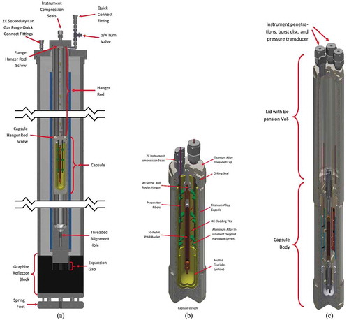
Leveraging on these requirements, the transient testing program has successfully deployed seven variants of a vehicle design in TREAT since its restart to date. The device is referred to as the minimal activation retrievable capsule holder (MARCH) irradiation vehicle system.Citation18 In this system the configuration comprises a capsule enclosed within a secondary can and hood, as seen in . To date, seven noticeably unique capsule types have been designed, five of which have been irradiated in various test configurations including ATF-sponsored irradiations in the separate effects test holder (SETH) and the MARCH static environment rodlet transient test apparatus (M-SERTTA) capsules. The SETH capsules, , were loaded with fueled rodlets, placed into the TREAT reactor, and exposed to a number of reactor pulses of varying energy depositions until rodlet disruption was observed. The M-SERTTA () was tested in a similar capacity to the SETH, however, it’s design features facilitate a larger instrumentation package.Citation18 The significant improvements of this MARCH system over previous concepts include modularity and standardization of hardware packages (streamlining the safety analysis and fabrication timelines) among other improvements.
Fig. 3. (a) Sectional view of MARCH system assembly, (b) SETH capsule, and (c) M-SERTTA module.Citation18
The outcomes of these early advancements on new variations of vehicles have been shown to produce reliable and incremental improvements over previous concepts. However, these newly deployed vehicles are all limited to a capsule concept. The continued development of nuclear fuels research requires increased phenomenological complexities to more aptly reflect in-reactor conditions, therefore loop vehicles that produce forced fluid flow are required. This study focuses on the development of a flowing water loop concept.
III. DESIGN BASIS
The transient testing of fuels and materials generates the information that is required for evaluating the performance of advanced nuclear reactor technology. The TREAT reactor is the ideal facility for performing this testing because of its flexibility, proven operation, and physical condition. The opportunity exists to develop advanced instrumentation and data collection that can support modeling and simulation needs much better than was possible in the past. In order to take advantage of these opportunities, test programs must be carefully designed to yield basic information to support modeling before conducting integral performance tests. Performance of experiments that emulate the thermal-hydraulic conditions of an accident at a nuclear power plant are both incredibly useful and difficult to accomplish in an out-of-pile setting. The ability to perform smaller-scale quasi-accident scenarios under prototypic thermal-hydraulic conditions provides the opportunity to collect data for material performance, validate data for safety codes, and provide guidance for developing in-pile experiments in a less burdensome environment.
III.A. Experiment Overview
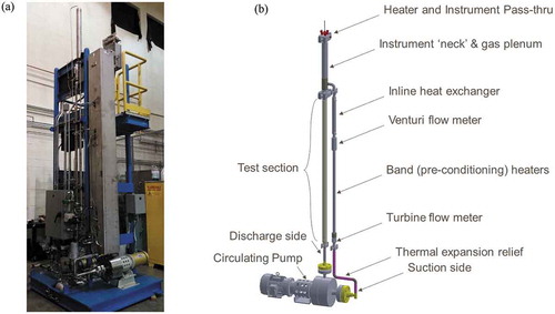
Researchers at Oregon State University have commissioned a first-of-its-kind out-of-pile test facility, the Transient Reactor Test Loop (TRTL) (), to investigate the thermal-hydraulic performance characteristics of a loop concept that may be placed within the TREAT reactor in the future. The TRTL was specifically designed to align with requirements from the ATF program and therefore supports operational conditions observed in a pressurized water reactor (PWR). The desired outcome of the TRTL is to better understand its phenomenological and performance characteristics in a low-risk out-of-pile setting prior to developing and implementing the in-pile prototype. The TRTL was therefore designed to mimic the thermal-hydraulic boundary conditions imposed on an in-pile loop of its form to demonstrate its characteristics and capabilities.Citation20–Citation23 The focus of the work described here details the rigorous process of constructing a roadmap for developing and performing out-of-pile experiments that simulate transient events specific to RIAs on the laboratory scale.Citation24
III.B. Methodology
The RIA transient is one in which it is postulated that a large positive quantity of reactivity is rapidly added to the core (or negative reactivity is rapidly removed from the core). A control rod ejection is the most commonly stipulated initiating event that causes an RIA. As a result, a power excursion occurs. If the reactivity removal is instantaneous, the power excursion follows an increasing exponential form until negative reactivity feedback is observed within the core, ultimately turning the reactor’s power around. In the most extreme scenario of an RIA, sufficient reactivity is added to the core to cause the reactor to go prompt supercritical causing a power “pulse.” It is this extreme case that is considered herein. The pulse transient is a complex one that can result in fluid phase change, and fuel/clad geometry compromise.Citation25 In large power pulses the possibility of cladding dryout is real, in which the cladding heat flux is sufficient to rapidly cause the fluid to experience a departure from nucleate boiling (DNB). This phenomenon has been studied rigorously under steady-state conditions and has caused difficulty in the credible understanding of phenomenological evolution under transient conditions. The DNB does affect flow boiling heat transferCitation26 and compromises the structural integrity of nuclear fuel materials. Accident scenarios such as RIAs provide conditions where the frequency of boiling crisis is much more likely to occurCitation27 and on much shorter timescales than loss-of-coolant or loss-of-flow accidents. Here, boiling crisis in the form of DNB is attributed to transient-induced heat flux values that exceed the critical heat flux (CHF) for a particular material under certain thermal-hydraulic conditions.
Empirically based correlations have been developed for several decades to predict DNB and the corresponding CHF (CitationRef. 28), however, the variety of conditions experienced during off-normal operations has led to the development of a host of highly specialized models that are applicable in limited scenarios. As a result, the knowledge base for CHF under transient conditions is considerably lessCitation25,Citation29 than for steady-state conditions. Bessiron et al.Citation30 and SakuraiCitation31 demonstrated that the value of CHF during RIA conditions is not only dependent on temperature and pressure, but also on the rate of energy deposition: faster-occurring transients result in higher CHF values. In addition, during short-lived transients (such as RIAs) there is a gap in CHF that cannot be accounted for through traditional models. A substantial gap (>20%) was noted between the CHF measured for transient experiments versus model prediction. The advancement of CHF models through continued benchmarking and exploratory testing is needed to better describe the phenomenology observed during transient events.Citation30,Citation31
It has been proposed that there are several factors that contribute to this gap that are specific in-pile considerations, such as gamma heating or coolant ionization; however, the exact source of this gap, while it has been observed and documented, has not yet been quantified experimentally. In addition, from an experimental standpoint it is quite difficult to predict the amount of power needed to produce CHF in a steady-state (or quasi-steady-state) case. Reducing the timescale to fractions of a second further complicates the problem and drastically reduces the response time for salvaging equipment and materials before failure occurs. The majority of the CHF models use a quasi-steady approach for transient CHF study. ZuberCitation28 and KutateladzeCitation32 proposed that the pool boiling CHF mechanism is based on hydrodynamic instability (HI), which has been the only analytical model to be widely accepted. In recent decades, other researchers have proposed variations of this model based on the extrapolation or modification of CHF correlations based on the HI mechanism.
The mechanism that drives the occurrence of CHF, as triggered by an RIA event, has been demonstrated to differ from the steady-state cases. Saito et al.Citation33 reported a direct transition to film boiling without reaching nucleation boiling, where bubbles nucleated on the surface and then coalesced to form a vapor blanket covering the entire heated surface that prohibits efficient heat transfer and eventually causes boiling crisis. SakuraiCitation31 further confirmed this phenomenon, which was termed heterogeneous spontaneous nucleation (HSN).
The ability to predict the onset of DNB during a transient event is limited by the lack of credible experimental data to better inform existing models.Citation34 Furthermore, the mechanisms that drive a DNB event, as suggested by the results of Saito et al., Sakurai, and others, seem to be influenced by the timescale of the precursor event. Depending on the duration of the accident source, the cause might be best described by either HSN or HI mechanisms (), where T refers to the time constant of an increasing power of exponential form.
Fig. 4. (a) Picture of TRTL and (b) rendering of TRTL primary loop.
Recall that the desired outcome of the TRTL is to better understand its phenomenological and performance characteristics in a low-risk out-of-pile setting prior to developing and implementing the in-pile prototype. Therefore, traits such as transient CHF are of relevance for a test facility of this form when considering RIA scenarios.Citation34
IV. FACILITY DESIGN
The focus of the work described here is to develop a rigorous process using out-of-pile testing under simulated RIA conditions to provide experimental data that support the phenomenological and performance characteristics, without contributions from aforementioned radiation-induced effects that have been observed during in-pile experiments. This study provides a roadmap for developing and performing experiments that simulate the power profile and energy deposition aspects of transient events specific to RIAs on the laboratory scale without the need for significant scaling analysis or reduced-scale experiments.
IV.A. Operating Range
The customer requirements for the TRTL include the capable steady thermal-hydraulic operation of the system under nominal PWR conditions and the ability to impose heat fluxes sufficient to generate CHF under RIA conditions. A tabulated form of the PWR operational conditions necessary to produce the customer requirements may be seen in the middle column of .
TABLE I Engineering Requirements for Operational Envelope
The TREAT reactor is capable of imposing sufficient reactivity on an experiment holding up to four rodlets (and possibly more),Citation35 however the scope of this study focuses on the design of a test vehicle holding one rodlet of standard TREAT testing length (24 in.). Flow rates were scaled to a single rod’s subchannel, producing a range of operational conditions between 1 and 25 gpm for a single channel. In a PWR, the spectrum and fluid facilitate a rather rapid pulse of as small as 60 ms for a pulse’s full-width at half-maximum (FWHM). This is presently not achievable with operations of the TREAT reactor, however efforts are presently underway to reach these conditions, therefore they are being considered a part of this study.
The operational envelope of the TRTL was designed to envelope the PWR conditions (right column in ). System pressures and temperatures were readily achieved in the TRTL design with the use of schedule 80 stainless steel Type-304 piping throughout. Considering the work of Sakurai,Citation31 a possible transition in phenomenological mechanisms that cause CHF occurred with FWHM equivalents of 25 to 30 ms (i.e., time constants at approximately 1 × 10⁻² from ), therefore the envelope of relevant FWHM was increased in the TRTL to accommodate this and facilitate these boundary conditions. In order to accommodate these rapid heat fluxes, the design and use of a new heater rod was required. The heater rod was 480 VAC wired in a delta configuration and located with ceramic insulator sleeves. Wires were placed within a clad material of the desired composition and the heater was thermally bonded with helium gas. Using the gas as the thermal bonding agent reduced the thermal inertia within the center of the heater and increased the rate at which heat flux increased on the outer surface of the cladding during a transient.
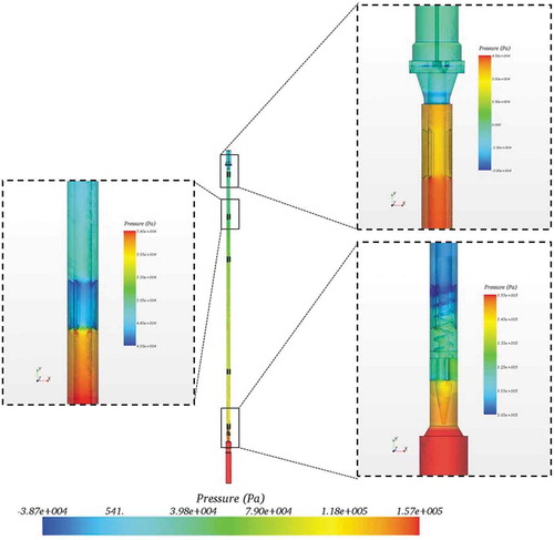
The pump selection was made through design and analysis iteration, while maintaining the requirements range in the middle column of . The final design of the primary loop piping and internals, shown in , was complemented by a rigorous hydraulic computational fluid dynamic analysis using STAR-CCM+ to accurately predict the head loss through the loop with varied flow rate. The outcome of this analysis (graphically shown in ) led to the selection of a 5-hp centrifugal Magne-Pump. The CFD analysis predicted a primary loop head loss of 45.7 ft at an equivalent 25 gpm (confirmed experimentally later to within 0.2% accurate). The lower range of this pump aligned with the customer requirements and significantly surpassed the upper-bound flow-rate requirements with a capacity of up to 45 gpm (note that this flow rate has only been briefly tested as it approached the flutter velocity of the heater rod).
Fig. 5. General phenomenological mechanisms and respective time constants for HSN versus HI (CitationRef. 30).
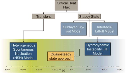
Fig. 6. (a) Isometric cut view and (b) isometric cut breakouts of TRTL primary loop.
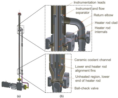
Fig. 7. Local pressure losses computed across the TRTL test section.
IV.B. Figures of Merit
Traditionally, CHF is determined as a combination of four factors: hydraulic diameter Dh, system pressure P, mass flow G, and thermodynamic equilibrium quality Xe. Therefore, particular emphasis was placed on the prescription of boundary conditions and the acquisition of measurements that reflect these fluid traits.
Transient fuel testing concentrated on the performance and containment of the fuel element; in particular, the performance of the cladding with respect to its ability to withstand an accident scenario and retain fuel material and fission products. Several design-basis parameters were assessed during transient fuel testing, including the performance limitations of the DNB ratio for PWRs, fuel temperature, the linear heat generation rate, fuel enthalpy, cladding strain, fuel burnup, cladding temperature, and cladding oxidation.Citation36 The variation of several of these parameters specifically requires nuclear heating or irradiated or radioactive material, and therefore can either only be performed in-pile and/or with fueled rods. However, there are three parameters remaining that provide a focused scope of work for developing out-of-pile transient testing: (1) CHF, (2) linear heat generation rate, and (3) cladding temperature. These FOMs, in concert with the other bulk coolant characteristics previously mentioned, were the basis for instrumentation selection and location within the TRTL.
IV.C. Instrumentation
With the FOMs determined, the focus turned to identifying the proper sensing tools and techniques to be able to acceptably satisfy them. Fundamentally, one must first ensure the adequate measurement of the continuum formulation: mass, momentum, and energy. Additional considerations were made for instrumentation with the aforementioned FOMs while also using the six guiding principles of good validation experiments identified by Oberkampf and AeschlimanCitation16 and best practices to increase experimental reliability.Citation37 The outset of the instrumentation selection exercise led to the outcomes detailed in , which along with numerous auxiliary and supporting operational instruments led to a total of 56 data channels collected on the TRTL.
TABLE II Instrumentation Plan and Respective Alignment with FOMs
From it may be noticed that the primary composition of the critical instruments to the characterization of FOMs are through pressure transmitters and thermocouples. While more sophisticated full-field measurement methods, such as particle image velocimetry and others, may be desired, their inclusion within the design of this system is prohibitive due to the extreme operating environment and thus the lack of availability for optical measurement methods. While the discrete spatial measurement of these instruments may limit the full-field characterization of phenomena, their relative instrument reliability under extreme environments, such as those considered herein, has been proven and deployed within the nuclear industry for decades. All instruments after receipt underwent a complete calibration against in-house standards compliant to ASME NQA-1 2008, -09A, and International Organization for Standardization 19025 standards.
Once the instruments were confirmed to produce a credible signal within their manufacturer’s specifications they were placed in their respective locations on the TRTL. Given their discrete spatial measurement, design placement of the instruments is critical in the acquisition of the desired information, particularly when measuring phenomena that are inherently local (such as CHF). presents the local placement of each critical instrument on the facility. indicates all critical pressure and flow measurements collected from the facility and their respective instrument routing. presents all critical temperature measurements to the facility, including those of the bulk coolant and wall measurement form. Note the redundant tags (e.g., TF-401a, TF-401b, TF-401c) for thermocouples. At each of the six unique axial lengths, three independent temperature measurements are collected from three thermocouples. This method of instrument design allows for the reduction of Von Mises’ uncertainty in instrument error during a transient, εv = (1/N)½, where N is the number of samples (three) collected. It additionally provides a level of assurance that temperature is being monitored and measured accurately during a transient as a result of the redundancy.
Fig. 8. (a) Schematic for the TRTL pressure and (b) temperature sensor arrangement [DP = differential pressure measurement, PT = gage-pressure measurement, FIT = volumetric flow measurement, TF = temperature measurement of fluid, and TW = temperature measurement at a wall (outer clad temperature).]
![Fig. 8. (a) Schematic for the TRTL pressure and (b) temperature sensor arrangement [DP = differential pressure measurement, PT = gage-pressure measurement, FIT = volumetric flow measurement, TF = temperature measurement of fluid, and TW = temperature measurement at a wall (outer clad temperature).]](/cms/asset/364c3143-0937-46d1-8100-8fd30b3b0aff/unct_a_1720559_f0008_oc.jpg)
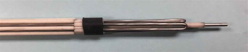
There are 16 Type-K thermocouples located along the test section, 15 of which are separated into five discrete locations along the flow channel, with three thermocouples secured radially around the heater rod at each location (). A single Type-K thermocouple is inserted down the centerline of the heater rod internal assembly (inside of the cladding) through the upper portal (). This thermocouple is shielded from the high-powered electrical wires by a ceramic (alumina) sleeve and traverses internally down the length (~1.3 m) of the heater rod through the void space between the sheath and the wires. Several Type-K thermocouples are installed throughout the remainder of the test loop (), including on the suction and discharge sides of the primary pump and at three locations along the downcomer section of the test loop. While the thermocouples within the test section serve as indicators of critical phenomena that might occur during a transient pulse, these thermocouples provide assurance of energy balance and safety margin during testing.
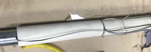
Fig. 9. Placement of pressure tube and thermocouple in the flow channel.

Fig. 10. High-powered heater rod with thermocouple sheath.
A series of five pressure tubes are installed along the length of the test section (). These tubes are connected to pressure transducers (PTs) that are installed at the top of the TRTL facility. These PT units serve as individual indicators of local pressure readings. Indicator tubes are connected to a high-resolution differential pressure transmitters (DPs) that were specifically chosen due to their ability to provide precise measurements with low DP readings (on the order of 0.1 psi) in high-pressure (up to 3500 psi) environments. Given that the steady-state condition for the high-pressure tests is around 2200 psi, the need for signal resolution on the order of a few psi provides clarity on the occurrence of a critical event during testing. Several high-limit (3500 psi) PTs are installed throughout the primary loop (). While the pressure tubes installed within the test section serve as indicators of critical phenomena that might occur during a transient pulse, the PTs also provide indication of safety margin during testing.
Fig. 11. Arrangement of pressure tube and thermocouples for test section.
Once the entire loop reaches thermal-hydraulic equilibrium, the data acquisition system is triggered to collect high-frame-rate data and the heater rod power is increased rapidly. The objective is to increase power in the rod until CHF occurs through observation of DNB. The occurrence of DNB is determined by the near-asymptotic change in temperature along the surface of the cladding during the transition to film boiling (measured using the internal heater thermocouples, ) along with the measurement of minute pressure changes within the annular flow channel by a set of strategically placed high-precision differential PTs that are located along the cylindrical test section (). This dual-sensor approach has been successfully implemented in previous nuclear fuel rod simulation experiments.Citation38
V. RESULTS AND DISCUSSION
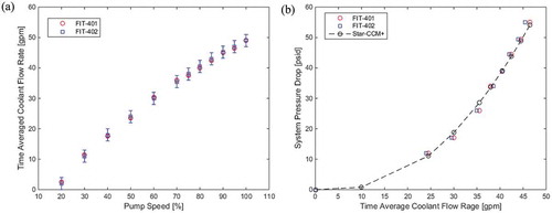
The FOMs detailed in the previous sections and noted within have been evaluated against experimental data and cross compared against ideal input quantities, independent measurements, and/or calculated values. These evaluations are presented herein. First, the accuracy of flow measurement was assessed through comparisons of independent flow meters. The venture flow meter (FIT-401) and turbine flow meter (FIT-402) data were collected at unique pump speeds across the operable range of the pump. compares the time-averaged measurement values reported for each of the pump speeds held at. Note that the error bars in reflect the sum of instrument uncertainty and stochastic variance, assuming a normal distribution about the mean measured value with a confidence of 95%. Additionally, a comparison of both flow meters was made at various flow rates and the respective hydraulic losses observed in the primary system, as seen in . In this case a comparison between the measured values and those acquired by STAR-CCM+ collected during the TRTL’s design process are made. Note that the relative agreement across the entire operational range of the system is good with a maximum observed difference of 0.2%. The measured comparison between independent flow measurement methods along with calculated values lends a high level of confidence in the system’s ability to reliably measure flow rate. Last, the reported system pressure used shows a nearly exact quadratic trend and agrees well with the predicted STAR-CCM+ results, further supporting the system’s ability to monitor and measure differential pressure locally and throughout.
Fig. 12. Flow and differential pressure measurement assessment.
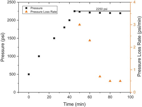
System pressure must be maintained and held constant during testing so as to ensure the appropriate boundary conditions for the RIA transients imposed by the TRTL. A hydraulic test was performed by statically loading the system at a slightly elevated temperature and operational pressure. The system’s response to this test over an approximate 2-h period is graphically presented in . Note that there is an observed pressure loss of approximately 3 psi over the course of a 1-h period. This is a .133% decrease in system pressure over this same period. Furthermore, RIA transients take place on the order of seconds, lending a high level of confidence that the system will be able to reliably maintain an appropriate pressure boundary condition for RIA testing.
Fig. 13. System pressure measurement assessment.
An adequate response and the acquisition of temperature throughout the system is paramount during testing. In order to test the responsiveness and sensitivity of the temperature measurements throughout, it was desired to impose a small and subtle amount of heat so as to most delicately observe the system’s response to these slight boundary condition changes. Thus a preconditioning heater was placed around the exterior of the loop (referred to as the low-wattage transient rod). The test began with the heater being turned on at a rate of 50% and observation being made of the influence of temperature measurement in the test section with the coolant flow rate maintained at the minimum continuous flow rate the pump would maintain (4 gpm). During the test, the heater was turned on for 20 s and then turned off for 80 s, followed by an increase of 75% output for 20 s and shut off for 80 s. This was repeated for 90% and finally for 100% power output (with a maximum heater power output of 5 kW). The goal of this exercise was to observe the thermal response of the thermocouples located within the test section and the relative time rate of change of temperature that the thermocouples recorded at each of these set points. The latter objective allowed for the assessment of heat losses through the test section. Three thermocouple time traces are presented and shown in . Note that only one trace may be seen as all thermocouples reported nearly analogous responses during this test.
Fig. 14. Temperature measurement assessment.
By computing the energy input to the system within each respective energized state and the relative time rate of change one may compare the system’s physical response to that of a system that otherwise would be adiabatic. Through this comparison it was found that when changing from 50% to 75% there was a 1.8% heat loss through the piping while when transitioning from 90% to 100% there was a 5.1% heat loss. Overall, when comparing all changed states, a net heat loss of 2.3% was found to occur.
Given the sensitivity of the thermocouples compared during this test and the relatively small ambient heat losses, the system was shown to have a sound thermal response and to be sufficiently insulated to verify energy states under nonideal conditions for RIA testing.
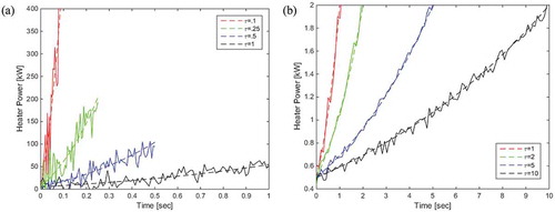
Last, the linear heat generation rate was assessed. A total of eight unique tests were conducted as shown in . In this case two types of transients were run: (1) a low-power transient with time constants ranging from 1 to 10 s and stopping at a maximum of 2 kW, and (2) a high-power transient in which power was increased to slightly less than that needed to reach the predicted CHF values for time constants of 0.1, 0.25, 0.5, and 1 s. These transients are shown in and , respectively. During these tests, the system was brought to pressure and maintained under high subcooling conditions. The control system was programmed to input an idealized exponential power increase with the specified time constant and the transient then initiated. The results shown in present the power’s response for all eight tests run. In , the dashed lines reflect the idealized input control values while the solid lines correspond to the measured and recorded values. The reported power in and is collected through the product of the measurements collected through the voltage transducer and the current transformer, respectively. Due to the short period over which these transients occurred, the power was shown to produce some levels of volatility. This is due to the compounded measurement uncertainties in both the transformer and transducer. For the low-power tests seen in the largest percent difference of the four transients was found to occur with the slowest time constant and reported to be approximately 10% (near the beginning of the transient), whereas the shortest time-constant for the high-power tests resulted in the largest percent difference at approximately 14% taking place at approximately 0.03 s in .
Fig. 15. Linear heat generation rate measurement assessment.
While no formal CHF results are shown herein, the metrology necessary to produce relevant boundary conditions for that of a flowing water loop in an out-of-pile test facility have been demonstrated against FOMs that align with the phenomenological and performance characteristics of the system needed to produce relevant RIA boundary conditions.
VI. SUMMARY
The restart of the TREAT reactor at the INL provides an impetus to revisit the development of historical data that are used to provide the safety case for the experimental design and evaluation of nuclear fuel. Development efforts are currently underway to expand upon the already existing static environment testing capabilities at the TREAT reactor. Many transient test objectives will be well suited to static environment testing, especially those tests that are intended to screen fuel concepts, identify phenomena, or exhibit behaviors that are not heavily dependent on heat transfer conditions. Furthermore, the execution of static environment testing is inherently less complex than tests based in a water loop vehicle.
However, the need exists to develop capabilities to perform more complex, integral testing campaigns, including those for flowing water reactor systems at prototypical operating conditions. This study presents the design basis, layout, instrument selection, and first-of-its-kind experimental data for an out-of-pile flowing water loop concept for use in the TREAT reactor. The basis for instrument selection and system design aligns with the six guiding principles of good validation experiments identified by Oberkampf and AeschlimanCitation16 and best practices to increase experimental reliability.Citation37 The identification of the FOMs for measurement was made for the system and found to include mass, momentum, energy, linear heat generation rate, equilibrium quality, pressure, mass flux, and as a corollary, CHF. A demonstration of the directly measured FOMs and evaluation of the system’s ability to monitor and characterize these FOMs are further expanded on and presented herein. Through objective assessment it was shown that the system aligns with the program’s requirements to support ATF transient tests in a flowing water loop and phenomenologically monitors the appropriate thermal-hydraulic characteristics of the system while doing so. The outset of this system and the demonstrated basis behind its alignment with the program and metrology will result in a new capability for performing at-pressure and at-temperature CHF tests in the future.
Acknowledgments
This work was funded under DOE contract DE-NE0008441; project 15-8761 as an integrated research project. The authors would like to extend their gratitude to the reviewers of this manuscript for their insightful observations and suggestions. Their recommendations significantly improved the quality and content of this manuscript relative to its original form, and for that the authors are grateful.
References
- D. WACHS, “Transient Testing of Nuclear Fuels and Materials in the United States,” JOM, 64, 12, 1396 (2012); https://doi.org/10.1007/s11837-012-0482-2.
- B. K. HEATH and C. C. RACE, “TREAT Restart Project,” Nucl. Technol., 205, 1369 (2019); https://doi.org/10.1080/00295450.2019.1589853.
- A. W. LaPORTA, “Transient Reactor Test (TREAT) Facility Initial Approach to Restart Criticality Following Extended Standby Operation,” Nucl. Technol., 205, 1290 (2019); https://doi.org/10.1080/00295450.2019.1565471.
- D. M. GERSTNER et al., “Safety Strategy and Update of the TREAT Facility Safety Basis,” Nucl. Technol., 205, 1266 (2019); https://doi.org/10.1080/00295450.2018.1556993.
- B. M. CHASE, A. W. LaPORTA, and J. R. PARRY, “Analysis of Core Characterization Transients for TREAT Restart,” Nucl. Technol., 205, 1312 (2019); https://doi.org/10.1080/00295450.2019.1585162.
- T. HOLSCHUH, S. WATSON, and D. CHICHESTER, “Metrology for Transient Reactor Characterization Using Uranium Wires,” Nucl. Technol., 205, 1336 (2019); https://doi.org/10.1080/00295450.2019.1599613.
- N. E. WOOLSTENHULME and J. D. WEIST, “ATF Transient Testing Pre-Conceptual Design and Engineering Considerations Summary,” INL/EXT-13-29898, Idaho National Laboratory (2013).
- N. WOOLSTENHULME et al., “Development of Irradiation Test Devices for Transient Testing,” Nucl. Technol., 205, 1251 (2019); https://doi.org/10.1080/00295450.2019.1590072.
- S. R. JENSEN et al., “Restart of the Transient Reactor Test (TREAT) Facility Neutron Radiography Program,” Nucl. Technol., 205, 1325 (2019); https://doi.org/10.1080/00295450.2019.1605780.
- C. JENSEN and A. FLEMING, “Development of Advanced Instrumentation for Transient Testing,” Nucl. Technol., 205, 1354 (2019); https://doi.org/10.1080/00295450.2019.1627123.
- J. BUMGARDNER and D. M. WACHS, “Restarting the Transient Reactor Test (TREAT) Facility Reactor for Nuclear Transient Testing Science: A Special Issue of Nuclear Technology,” Nucl. Technol., 205, iv (2019); https://doi.org/10.1080/00295450.2019.1650605.
- T. HOLSCHUH et al., “Transient Reactor Test Facility Advanced Transient Shapes,” Nucl. Technol., 205, 1346 (2019); https://doi.org/10.1080/00295450.2018.1559712.
- C. L. POPE et al., “Transient Reactor Test (TREAT) Facility Design and Experiment Capability,” Nucl. Technol., 205, 1378 (2019); https://doi.org/10.1080/00295450.2019.1599615.
- Quality Assurance Requirements for Nuclear Facility Applications, Vol. NQA-1, American Society of Mechanical Engineering, Standard (2008).
- Quality Assurance Requirements for Nuclear Facility Applications Addenda, Vol. NQA-1A, American Society of Mechanical Engineering, Standard (2009).
- W. J. OBERKAMPF and D. P. AESCHLIMAN, “Issues in Computational Fluid Dynamics Code Verification and Validation,” Aiaa J., 36, 5, 733 (1998); https://doi.org/10.2514/2.456.
- INL/EXT-13-29898, N. E. WOOLSTENHULME and J. D. WIEST, Eds., p. 76, Idaho National Laboratory (2013).
- “Nuclear Technology Research and Development,” INL/EXT-19-55844, N. WOOLSTENHULME, Ed., Idaho National Laboratory (2019).
- J. CARMACK, “Future Transient Testing of Advanced Fuels,” INL/EXT-09-16392, pp. 1–48, Idaho National Laboratory (2009).
- D. L. LaBRIER and W. R. MARCUM, presented at the American Nuclear Society Annual Mtg., San Francisco, California, Vol. 116, p. 1397 (2017).
- D. L. LaBRIER, W. R. MARCUM, and J. NYLANDER, presented at the American Nuclear Society Annual Mtg., Philadelphia, Pennsylvania, Vol. 116, p. 1113 (2018).
- D. L. LaBRIER et al., “On the Performance of the Transient Reactor Test Loop (TRTL),” Proc. American Nuclear Society Annual Mtg., Philadelphia, Pennsylvania, Vol. 118, p. 1130, American Nuclear Society (2018).
- D. L. LaBRIER et al., Proc. 18th Int. Topl. Mtg. on Nuclear Reactor Thermal Hydraulics, Vol. 18, pp. 4983–4993, American Nuclear Society, (2019).
- “Status Report on Development of TREAT Water Loop,” INL/EXT-19-55730, N. WOOLSTENHULME, Ed. pp. 1–43, Idaho National Laboratory (2019).
- J. LEUNG, “Transient Critical Heat Flux and Blowdown Heat-Transfer Studies,” NUREG/CR-1559, Argonne National Lab (1980).
- Y. SIBAMOTO et al., “In-Pile Experiment in JMTR on the Radiation Induced Surface Activation (RISA) Effect on Flow-Boiling Heat Transfer,” J. Nucl. Sci. Technol., 44, 2, 183 (2007); https://doi.org/10.1080/18811248.2007.9711272.
- L. O. JERNKVIST and A. R. MASSIH, Eds., “Nuclear Fuel Behaviour Under Reactivity-Initiated Accident (RIA) Conditions,” Nuclear Energy Agency-Organisation for Economic Co-operation and Development (2010).
- N. ZUBER, “Hydrodynamic Aspects of Boiling Heat Transfer,” PhD Thesis, University of California (1959).
- K. PASAMEHMETOGLU, “Transient Critical Heat Flux,” PhD Thesis, University of Central Florida (1986).
- V. BESSIRON, T. SUGIYAMA, and T. FUKETA, “Clad-to-Coolant Heat Transfer in NSRR Experiments,” J. Nucl. Sci. Technol., 44, 723 (2007); https://doi.org/10.1080/18811248.2007.9711861.
- A. SAKURAI, “Mechanisms of Transitions to Film Boiling at CHFs in Subcooled and Pressurized Liquids due to Steady and Increasing Heat Inputs,” Nucl. Eng. Des., 197, 3, 301 (2000); https://doi.org/10.1016/S0029-5493(99)00314-3.
- S. S. KUTATELADZE, “Mechanisms of Transitions to Film Boiling at CHFs in Subcooled and Pressurized Liquids Due to Steady and Increasing Heat Inputs,” J. Tech. Phys., 20, 11, 1389 (1950).
- S. SAITO et al., “Development of In-Reactor Fuel Behavior Observation System,” J. Nucl. Sci. Technol., 18, 6, 427 (1981); https://doi.org/10.1080/18811248.1981.9733275.
- S. LEE et al., “Comparison of Steady and Transient Flow Boiling Critical Heat Flux for FeCrAl Accident Tolerant Fuel Cladding Alloy, Zircaloy, and Inconel,” Int. J. Heat Mass Transfer, 132, 643 (2019); https://doi.org/10.1016/j.ijheatmasstransfer.2018.11.141.
- “Fuel Cycle Research & Development Advanced Fuels Campaign,” INL/LTD-15-36768, A. BEASLEY et al., Eds., Idaho National Laboratory (2015).
- N. TODREAS and M. KAZIMI, Nuclear Systems Volume I: Thermal Hydraulic Fundamentals, CRC Press (2011).
- H. W. COLEMAN and W. G. STEELE, Experimentation, Validation, and Uncertainty Analysis for Engineers, 3rd ed.,John Wiley & Sons, Inc., Hoboken, New Jersey (2009).
- A. Z. MESQUITA and R. R. RODRIGUES, “Detection of the Departure from Nucleate Boiling in Nuclear Fuel Rod Simulators,” Int. J. Nucl. Energy, 2013, 1 (2013); https://doi.org/10.1155/2013/950129.