
Abstract
Energy markets are changing because of (1) the addition of nondispatchable wind and solar electric generating capacity and (2) the goal of a low-carbon energy system. The large-scale addition of wind and solar photovoltaics results in low wholesale electricity prices at times of high wind and solar output and high prices at times of low wind and solar input. The goal of a low-carbon energy system requires a replacement energy production system with assured peak energy production capacity.
To minimize costs, capital-intensive nuclear reactors should operate at base load. To maximize revenue (minimize sales at times of low prices and maximize sales at times of high prices), the power cycle should provide variable heat and electricity. This requires the power cycle to (1) include heat storage that enables peak heat and electricity output that may be several times base-load reactor output and (2) provide assured peak power production. Assured peak power production requires the capability to efficiently burn low-carbon fuels such as hydrogen and biofuels. Alternatively, nuclear systems with base-load reactors can be built to produce peak electricity and storable hydrogen for industry, biofuels, and other markets. All power reactors with appropriate system designs can meet these requirements.
The lowest-cost technologies for heat storage, assured peak power production, and hydrogen production require high-temperature heat. This economically favors salt-cooled reactors with the average temperature of delivered heat of about 650°C versus heat delivered at lower average temperatures from other reactors such as light water reactors: 280°C, sodium-cooled reactors: 500°C, and high-temperature helium-cooled reactors: 550°C. Salt-cooled reactors include (1) Fluoride-salt-cooled High-temperature Reactors (FHRs) with solid fuel and clean salt, (2) Molten Salt Reactors (MSRs) with fuel dissolved in the salt, and (3) fusion reactors with salt blankets. Future energy markets, nuclear systems (heat storage, assured peak energy production capacity, and hydrogen production) designed for such markets and the power cycle technologies that economically favor salt reactors are described.
I. INTRODUCTION
Fossil fuels are a remarkable source of energy because they are relatively inexpensive, easy to store and transport, and capable of providing low-cost dispatchable energy. The capital cost of fossil power plants, furnaces, and other power conversion systems is low relative to the cost of fossil fuels. It is therefore economic to operate these systems at part load to provide economic variable electricity, mechanical work, and heat to the customer. In this fossil fuel–dominated world, nuclear power plants (NPPs) that have high capital cost and low operating cost have been developed primarily for centralized electricity production and operated to provide base-load electricity to minimize production costs. Fossil fuels provide the variable electricity to the grid to match production with demand.
The world is undergoing two one-time changes in energy markets: (1) the introduction of large-scale nondispatchable wind and solar photovoltaics (PV) that have low levelized cost of electricity (LCOE) production in good locations and (2) the goal of a low-carbon economy with no emissions of carbon dioxide to the atmosphere. Section II discusses the impacts of these changes on energy markets (electricity, residential, commercial, transportation, and industrial) and the resultant requirements for future nuclear power systems to be economically competitive in these markets.
The market changes create incentives for base-load reactors with large-scale heat storage and the ability to produce assured peak power above the base-load capacity to deliver variable electricity, heat, and hydrogen. These capabilities maximize plant revenue. The general power system designs to achieve these new capabilities are described in Sec. III.
The required systems can be coupled to any power reactor with the appropriate choices of heat storage and power cycle (steam or Brayton) technologies. Different reactor types deliver heat at different temperatures (). Section IV discusses how the higher temperature of delivered heat from salt reactors reduces the costs of these power systems relative to other reactor systems and creates a competitive market-based economic advantage to develop and deploy salt-cooled reactor systems.
TABLE I Temperatures of Delivered Heat from Different Reactors
Liquid salt reactors include Fluoride-salt-cooled High-temperature ReactorsCitation1 (FHRs), Molten Salt Reactors (MSRs), and fusion systems with fluoride salt blankets.Citation2 MSRs (CitationRef. 3) include thermal-spectrum MSRs that use fluoride salts and fast-spectrum MSRs with fluoride or chloride salts. Only thermal-spectrum MSRs have been built. These salts have melting points typically between 450°C and 550°C; thus, the minimum temperature of delivered heat is 550°C or higher. Practical economic materials for heat exchangers typically limit peak temperatures between 700°C and 750°C. Salt boiling points are above 1200°C; thus, all of these machines operate at low pressures.
Section V provides the conclusions. The term “renewables” (implying wind and solar) is not used herein because nuclear energyCitation4 is capable of providing energy for a world of 10 billion people with the current per capita energy consumption of the United States.
II. MARKETS
Markets define the requirements for energy production systems. The starting point for a long-term market assessment is the total heat and electricity markets of the United States (Sec. II.A). The question is then asked of how these markets will evolve with (1) the addition of large scale wind and solar and (2) the goal of a low-carbon economy. This assessment is then used to define what is required of a nuclear system to maximize revenue. This analysis is based on conditions in the United States, but the broad conclusions are applicable to most countries.
II.A. Energy Demand: Who Is the Customer?
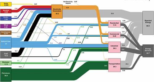
shows the energy economy of the United States from sources of energy (nuclear, wind, solar, natural gas, etc.) to the ultimate customer (residential, commercial, industrial, and transportation). Electricity is an energy carrier and effectively acts as a fifth class of customer. Almost all energy today is provided by fossil fuels. Fossil fuels allow each fossil fuel to separately supply different end users. We have independent energy transport systems for electricity, natural gas, oil, and coal. Most energy is consumed as heat, not as electricity (orange lines in ). This includes the transport sector where heat engines (internal combustion and jet) are used to move cars, trucks, and aircraft.
Fig. 1. Estimated energy consumption in 2018: 101.2 quadrillion BTU (quads) (CitationRef. 5)
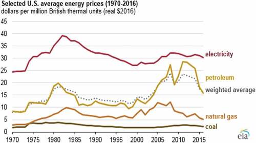
shows U.S. energy prices for major energy sources over the last 50 years. The cost of electricity (work) is about six times the cost of natural gas, which is a heat source. The price difference is a consequence of two factors. First, the laws of thermodynamics require several units of heat to produce a unit of electricity; thus, the cost of electricity is a multiple of any heat source. Second, electricity requires an electrical grid to move from generator to user. Typically, half the cost of electricity is in production, and half is in delivery.
Fig. 2. U.S. energy prices over 50 years (CitationRef. 6)
shows the LCOE and levelized cost of heat (LCOH) from different energy sources. The LCOE is from LazardCitation7 while the LCOH is based on the heat-to-electricity efficiency of different types of power plants. Wind and solar costs are at sites with good wind and solar conditions. Technologies that directly produce electricity (wind and utility solar) at good locations have relatively low electricity production costs. However, they produce relatively expensive heat since one unit of electricity yields one unit of heat. Technologies that produce heat [natural gas, nuclear, concentrated solar power (CSP), etc.] produce lower-cost heat but make more expensive electricity because it takes several units of heat to produce a unit of electricity. As discussed below, electricity grids require dispatchable electricity to provide electricity at all times including times of low wind or solar conditions; thus, low-cost electricity systems contain some mixtures of dispatchable and nondispatchable electricity.
TABLE II Levelized Cost of Electricity and Heat in the United States
These are not the full LCOEs because there are also system costsCitation8 such as grid upgrades that are higher for wind and solar than for other generating technologies. In the United States those costs for wind are estimated to add $16/MW·h (all $ units are in United States dollars) if wind provides 10% of the electricity demand and $20/MW·h if wind provides 30% of the electricity demand versus about $2/MW·h for nuclear and $0.5/MW·h for natural gas. The corresponding solar costs are estimated at $15/MW·h and $28/MW·h. As a consequence, natural gas is today in the United States the low-cost option. Various subsidies result in lower costs of wind and solar to the investor in parts of the United States. These same system costs apply to the LCOH when the heat is generated by electricity (wind and solar PV) but do not apply to natural gas or nuclear energy when providing heat. However, there is the requirement for users of nuclear heat to be collocated with the reactor. Natural gas and nuclear are the low-cost sources of heat.
Several conclusions follow from examination of energy markets. Nuclear reactors produce heat, which is what most customers require. Nuclear energy is more competitive in heat markets than electricity markets. If there are constraints on carbon dioxide emissions, large customers such as the industrial sector will not convert to electricity because of the high cost of electricity relative to heat. We examine separately the future of the five energy markets (electricity, residential, commercial, transportation, and industrial) in the context of (1) adding large-scale wind and solar and (2) going to a low-carbon energy system.
II.B. Electricity Markets
II.B.1. Structure of Electricity Markets
The electricity sector has two primary requirements: (1) produce electricity measured in kilowatt hours and (2) provide assured electric generating capacity measured in kilowatts. In an all-fossil system, the required generating capacity (kilowatts) matches the peak electricity demand plus some additional generating capacity to allow for power plants that are shut down for maintenance. The major historical exceptions, such as in California, have been utility systems with nondispatchable run-of-the-river hydroelectric generating systems where the output depended upon rainfall and melting snow. In these systems the required generating capacity (fossil plus hydro) is larger than the peak electricity demand because at times of low river flow, little electricity was generated from the hydro facilities.
Historically, most electricity has been produced from fossil fuels (coal, oil, and natural gas). The cost of a power plant was low relative to the cost of fuel; thus, it was economic to produce variable electricity by varying the output of the power plant. When NPPs were developed, they had higher capital costs but lower operating costs. The most economic mode of operation was to operate NPPs at base load with fossil fuel power plants meeting the variable electricity demand.
In the United States there are regulated and deregulated utilities. Economic theory predicts that a perfectly regulated utility and perfectly deregulated market will obtain identical results, recognizing that there are no perfect regulators or perfect markets. In regulated markets, a single utility owns and operates electric generating systems, the transmission system, and the distribution system. The allowed profits by the regulator depend upon how well the utility performs. Historically, performance has been measured by how well the regulated utility minimized total electricity costs. In a deregulated market, electric generators compete for the sale of electricity where the transmission grid operator defines the market rules. There are two primary sources of revenue for electricity generators in these markets:
Electricity markets (kW·h): Each electricity generator bids to produce a certain number of kilowatt hours for each hour, typically for the next 24 h. The grid operator predicts the amount of electricity needed each hour and accepts a sufficient number of bids to meet the total electricity demand for each hour. Every winning bid below the most expensive winning bid is paid the same for each kilowatt hour of electricity produced for that hour. A nuclear or run-of-the-river power plant will bid a low price to avoid shutting down. The price of electricity for each hour is determined by the electric generator with the highest operating costs.
Capacity markets (kW): The grid operator must assure there are no electrical blackouts. The first option is to operate only with electricity markets where at times of peak demand the wholesale electricity prices may increase by a factor ≥100 to encourage power generators to build plants that produce electricity for <100 h/year. The alternative is a market for assured generating capacity (kilowatts) where generators bid to provide assured electricity capacity independent of payments for electricity (kilowatt hours).
There are other payments for specialized grid services, but these sources of revenue are small.
II.B.2. Addition of Nondispatchable Wind and Solar
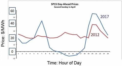
The large-scale addition of wind and solar has massive electricity market impacts. Wind and solar in the right locations provide low-cost electricity () at times of high wind and solar output but no assured generating capacity. shows the impact of solar additions in California on a spring day in 2012 and 2017. In 2012 the price of electricity was controlled by natural gas with peak wholesale electricity prices in the early evening at times of peak electricity demand. The large-scale addition of solar resulted in collapse of wholesale electricity prices in the middle of the day with higher prices before sunrise and as the sun goes down. Wholesale prices in the middle of the day can become negative as conventional power plants bid negative prices to remain online at minimum output, so they are able to ramp up in the evening when electricity prices climb. The value of solar decreases as more solar is addedCitation9 as has been seen in multiple markets. This limits the large-scale economic deployment of solar.
Fig. 3. Wholesale California electricity prices over 24 h on a spring day
Recent studiesCitation10 of the impacts of wind and solar on California electric wholesale markets provided insights to the long-term market effects of wind and solar. In the United States wholesale electricity prices have been decreasing. The primary cause on a national basis has been the reduction of natural gas prices from fracking. However, California has aggressively pushed wind and solar relative to most of the United States. As a consequence, California provides a basis to understand the future impacts of wind and solar on wholesale electricity prices. Three conclusions follow from these studies:
Revenue to base-load power plants goes down with large-scale wind and solar additions.
There are large increases in the volatility of electricity prices. This creates large economic incentives for dispatchable electricity with fast response to produce electricity at times of higher prices (low wind/solar output) and avoid selling electricity at times of low or negative prices (high wind/solar output). Today, this favors gas turbines.
As more wind or solar is added, the revenue per installed kilowatt of capacity of wind and solar goes down. This effect is larger for solar than wind. Other studiesCitation11 have come to the same conclusion. Revenue collapse limits the large-scale deployment of wind and solar unless large subsidies or markets are developed to absorb massive amounts of electricity to reduce times of very low electricity prices.
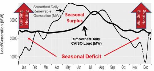
Historical studiesCitation12 on electricity prices that cover multiple regions of the United States come to similar conclusions. We are going through a one-time transition of added nondispatchable wind and solar with low LCOEs in those parts of the country with high-quality wind and solar resources. This change in the market creates incentives for electricity storage systems to buy electricity at times of low prices and sell at times of high prices to address hourly-to-daily price variations in electricity prices (). However, there are limits to such storage systems because of the seasonal variations in wind and solar. shows the smoothed electricity demand for California over a period of 1 year and the smoothed generating profile of wind and solar over the same time if sufficient wind and solar were built to meet the total electricity demand of California. That is, the total production of electricity from wind and solar matches total demand for electricity. There is a seasonal mismatch between production and demand with excess production in the spring and early summer.
Fig. 4. Smoothed daily California electricity demand and smoothed daily renewable generation with total annual renewable generation equal to total annual electric demand (CAISO = California Independent System Operator) (courtsey of S. Brick, California Case Study, Clean Air Task Force)
If the goal is to produce all electricity from wind and solar, the system requires three components (). Electricity is generated by wind and solar with storage systems to better match production with demand over a period of days. To address the seasonal mismatch between production and demand, gas turbines, fueled with hydrogen or biofuels, could be used.
Fig. 5. Nondispatchable wind and solar energy system design
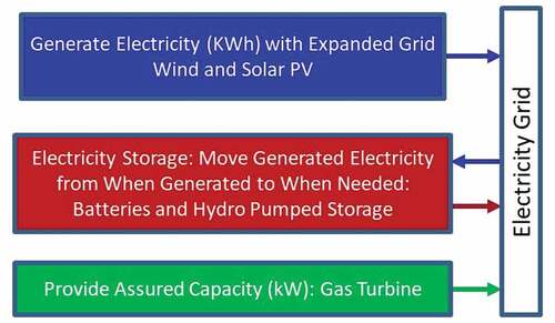
The cost of electricity (kilowatt hours) from wind and solar is low. However, for every unit of generating capacity (kilowatts), large amounts of energy storage and assured generating capacity are needed. The economics of large-scale wind and solar systems is determined by the economics of storage and assured generating capacity, not by the cost of producing electricity from wind and solar systems. This is why electricity costs have gone up in Germany, Denmark, California, and other locations that have attempted to create electricity systems based on wind and solar. Small amounts of wind and solar reduce electricity prices while large amounts increase prices.
The addition of wind and solar has two implications for nuclear energy. First, low-cost wind and solar reduce revenue for base-load NPPs. Second, if society is to economically benefit from the low cost of wind and solar electricity when available, one needs a second generating system with very low-cost storage and the capability to provide peak assured generating capacity, which an advanced nuclear power system can provide.
II.B.3. Implications of Restrictions on Carbon Dioxide Emissions
The requirement of low-carbon electricity has large impacts () on energy systems. Fossil fuels have reasonable costs, are easy to transport, and have low storage costs. As a consequence, the cost of a shipload of coal, oil, or liquefied natural gas (LNG) is about the same in New York Harbor as in Shanghai. The result is a relatively flat price of energy almost everywhere in the world. If carbon dioxide emissions must be eliminated, facilities that burn fossil fuels must capture carbon dioxide and sequester it, i.e., carbon capture and sequestration (CCS). Carbon dioxide sequestration requires the appropriate geology; it is geographically limited like hydroelectric facilities. Locations with inexpensive natural gas, such as Texas, will generally have viable sequestration sites in sedimentary rocks. In many geologies CCS is impossible. The permeability of granitic and many other common rocks is too low to store carbon dioxide.
TABLE III Characteristics of Low-Carbon Energy Sources
Carbon dioxide can be shipped by pipeline to suitable sites for sequestration, but there are costs and significant constraints on the siting of long-distance carbon dioxide pipelines relative to natural gas pipelines. Natural gas is lighter than air whereas carbon dioxide is heavier than air. A break in a natural gas pipeline results in natural gas dispersing upward into the atmosphere. Whether it escapes to the atmosphere or burns, the hazards are very local. Carbon dioxide is heavier than air; it is a ground hugger that can asphyxiate people (as with the Lake Nyos disaster) at a distance away from a break. These transport constraints place geographical limitations on fossil fuel plants with CCS.
Recent studiesCitation13–16 have modeled the electricity systems in different parts of the world to determine the optimum electricity system in terms of minimizing average electricity costs with different constraints including (1) with and without nuclear power and (2) different limits on carbon dioxide emissions to the atmosphere. shows results from the Massachusetts Institute of Technology (MIT) study “The Future of Nuclear Energy in a Carbon Constrained World”Citation13 for the two extreme cases: Texas in the United States and the Beijing region in China. Texas has low-cost natural gas, low-cost wind and solar, and relatively high construction costs for NPPs. China is the reverse with high-cost natural gas, higher-cost wind and solar, and low construction costs for NPPs.
Fig. 6. Average price of electricity versus carbon constraint for Texas and Tianjin-Beijing-Tangshan
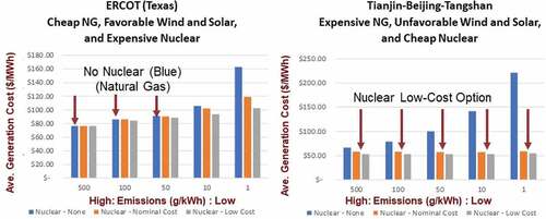
Three future scenarios are shown in for each carbon dioxide emission limit: no nuclear (blue), nominal cost nuclear (orange), and low-cost nuclear (gray). In Texas the low-cost option with no carbon constraints is natural gas; thus, the cost of electricity does not change until carbon dioxide constraints limit the use of natural gas. No nuclear is built. As carbon emissions become more constraining, added wind and solar are used to reduce the use of natural gas. If nuclear power is not allowed, at low carbon emissions one needs massive excess wind and solar generating capacity with storage to provide assured generating capacity. This rapidly drives up the cost of electricity. China is the reverse case with low-cost nuclear power and expensive alternatives; thus, if nuclear power is allowed, there is little change in the cost of electricity with changes in carbon constraints. Without nuclear power, electricity costs increase rapidly with increased carbon constraints.
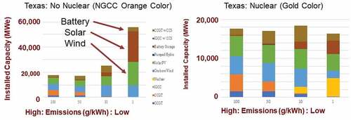
shows the required capacity to meet electricity grid requirements in Texas for the case of no nuclear and nominal-cost nuclear. At very low carbon dioxide emissions, the no-nuclear case in Texas has almost 60 000 MW of capacity; most of that capacity is wind, solar, and batteries required to assure delivery of electricity. If nuclear is allowed, the total generating capacity is slightly less than 20 000 MW. The high cost of all-renewable scenarios is the cost of providing assured generating capacity.
Fig. 7. Installed electricity capacity versus carbon dioxide constraints with and without nuclear power (NGCC = natural gas combined cycle; CCGT = combined cycle gas turbine; IGCC = integrated gasification combine cycle)
The results of other studies reach the same conclusion. To avoid large increases in electricity costs with tight constrains on carbon dioxide emissions, one requires a dispatchable electricity source with assured peak electric generating capacity. Nuclear energy can fill that role, but there are other options in some locations, such as areas with massive hydroelectric capacity. There are caveats with these studies. In each case the existing demand profile for electricity was used. That demand profile will change if the entire economy is decarbonized, as discussed below. Second, the studies assumed electricity storage technologies and NPPs that did load-following. They did not evaluate the newer options of adding heat storage to NPPs for variable electricity output from base-load plants; that is, these studies did not consider redesigning nuclear systems as discussed below.
II.C. Residential/Commercial
The U.S. electricity and heat inputs into the residential and commercial markets are about equal (). The heat input is primary for building heating with a massive peak in the winter months that is supplied by natural gas. Peak natural gas demand is met by two mechanisms. The first mechanism is massive quantities of natural gas stored underground near consumers to meet winter demand. In the United States this storage capacity is about a fifth of a year of natural gas consumption.Citation17 It would not be economically viable to build long-distance pipelines to meet peak demand. The second mechanism is fuel switching by industry and utilities to fuel oil at times of large home heating demand to free natural gas for home heating.
These options do not exist in a low-carbon world. In a low-carbon world much of this heating demand will be met by electricity that will move the seasonal peak electricity demand from summer to winter in northern climates. This peak demand will occur on cold days before sunrise at times of no solar input and minimum wind input. Wind output is lower at night. Multiday cold fronts will deplete electricity storage systems with less than multiday storage. The other low-carbon alternatives are hydrogen and biofuels that are discussed later.
Some parts of the world, such as Quebec, Canada, use electric heating. In most of these areas, peak electricity demand is met by massive hydroelectric capacity using the stored energy of water behind reservoirs. That option is not available for most of the United States, implying the need for large-scale added assured peak electric generating capacity for northern climates.
II.D. Transportation
The transport sector consumes about the same amount of energy as the industrial sector, primarily as fossil liquid hydrocarbon fuels, i.e., gasoline, diesel, and jet fuel. There are three competing low-carbon replacement technologies where choices will have large effects on the relative future demands for heat, electricity, and hydrogen—alternative products from nuclear energy systems. Those choices may strongly impact nuclear plant design (Sec. III). For some transport sectorsCitation18 such as aircraft, biofuels will be the preferred option, but there are no clear winners for cars and light trucks. Different countries may adopt different light-vehicle fuels.
II.D.1. Electricity
Electric vehiclesCitation19 are proposed to replace gasoline and diesel in the light-vehicle market (cars and light trucks). There are two challenges: (1) battery cost and performance and (2) interface with the electricity grid. The cost of batteries is decreasing, but the cost of the raw materials in the battery (lithium, cobalt, etc.) may limit future cost reductions, so total vehicle costs remain above that of vehicles with internal combustion engines. Unlike heavy trucks or airplanes, the primary cost of automobiles is in the vehicle; thus, increases in vehicle costs present major problems for lower-income families.
Electric vehicles must be recharged from the electricity grid. A recent studyCitation20 examined likely times when these vehicles will be recharged in California () and found most recharging will be done in the early evening shortly after the sun sets, i.e., the time of peak daily electricity demand. This is caused by work schedules and single-car families that want assured car availability. That requires recharging vehicles in the early evening. From the perspective of the electricity grid, an all-electric vehicle implies massive grid and power plant expansion to meet a peak demand that lasts a few hours per day. There are proposals to require time-of-day electricity prices and other mechanisms to change recharging times; but all of these options require major changes in human behavior with most of the burden falling on single-vehicle families with lower incomes while reducing the advantages of cars—transportation on demand.
Fig. 8. Projected California plug-in electric vehicle (PEV) electricity demand 2017–2025 versus time of day
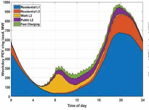
In this context, there is a massive difference between all-electric vehicles and plug-in hybrid electric vehicles that have (1) batteries and (2) engines that could be fueled using biofuels, hydrogen, and other storable fuels. With a plug-in hybrid vehicle, there is assured transportation if the battery is not charged. The owner of such a vehicle would prefer to recharge when electricity prices are at a minimum and willing for the utility to partly control times of recharging. Plug-in hybrids have the potential to significantly reduce daily variations of electricity prices, reduce electricity prices, reduce investment in the electricity system, and result in a much more robust energy system.
There is a second effect of all-electric vehicles in northern climates. With internal combustion engines, heat for the passenger compartment is provided by the engine, which is waste heat at no cost. With all-electric vehicles heat is provided by batteries. This can substantially increase winter electricity demands.
II.D.2. Hydrogen
Significant work is underway to develop hydrogen-fueled vehiclesCitation19 and hydrogen-rich fuels such as ammonia. This is considered the main-line option in Japan and Korea. Hydrogen can be produced by multiple methods (Sec. IV), is storable, and is transportable. Beyond the vehicle, the primary challenge is the requirement to develop the refueling infrastructure. If hydrogen is adopted, it is likely to be first used in heavy trucks, delivery vehicles, trains, and ships that require less refueling infrastructure and have fewer weight constraints for on-board hydrogen storage systems.
II.D.3. Biofuels
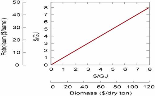
Studies indicate that up to 25% of the global energy demand could be met by biofuelsCitation21,Citation22 meeting most of the transportation fuel demand. This does require changing agriculture practicesCitation23 to meet the multiple needs for food, fiber, and energy. The cost of biofuel (lignocellulosic) feedstock ($20 to $100/ton) is sufficiently low that biofuels are potentially competitive with fossil liquid fuels ().
Fig. 9. Cost of biomass feedstock versus price of petroleum
In the area of biomass-to-liquid fuel conversion, there are three complementary strategies for liquid transport biofuels that can strongly affect the quantities of liquid fuels per ton of feedstock and net CO2 releases to the air:
Biomass as feedstock and energy source: Biomass can be used as the feedstock for a biofuels refinery and the energy source to operate the biofuels refinery.
Biomass as a feedstock: The conversion of biomass into liquid fuels is energy intensive. If external sources of heat and hydrogen from nuclear, wind, and solar can be provided, the liquid fuel yield per ton of biomass feedstock can be doubled with dramatically lower feedstock requirements. Hydrogenation of biofuelsCitation24 enables production of gasoline, diesel, and jet fuels, which are direct replacements for fossil fuels. The biggest component of biomass is plant cellulose [(C6,H12O6)n], comprising about a third of all biomass. The generic composition for hydrocarbon fuels is [(CH2)n]. Converting biofuels into high-quality hydrocarbon fuels requires at a minimum two hydrogen atoms to remove each oxygen atom. The hydrogen input requirements for biofuels could become 10% of the total energy demand and make hydrogen production, not electricity, the primary nonbiomass energy input into the transport sector ().
Biomass for low-carbon biofuel and fossil liquid fuels: Many of the biomass–to–liquid fuel processes produce nearly pure CO2 as a by-product that could be sequestered underground. The sequestration of this CO2 would allow burning an equivalent amount of fossil liquid fuel to be used with no net change in atmospheric CO2 levels.
For aircraft and other vehicles that require the high energy density of hydrocarbon fuels, hydrocarbon biofuels will likely replace jet fuels. Detailed studiesCitation25 of alternative fuels for aircraft show that liquid hydrogen and other such options result in significant reductions in aircraft efficiency. Lower-density fuels result in larger aircraft with larger resistance to airflow that increases fuel demand. Similarly, in long-distance trucks the volume and weight of lower-density fuels decrease truck cargo capacity.
II.D.4. Other Considerations
Today, the fossil fuel transport sector is almost independent of the electricity and industrial heat sectors. However, in a low-carbon world, transportation fuel choices will be tightly coupled to the electricity, hydrogen, and heat sectors. This implies that nuclear energy may become a major primary energy source for the transport sector. Grid challenges will likely limit all-electric vehicles with the widespread adoption of hybrid plug-in vehicles using (1) biofuels that use hydrogen in the production process or (2) hydrogen. Hydrogen is likely to become a major market for nuclear energy.
II.E. Industrial
The U.S. industrial heat demand is about twice the total electricity production. Direct electrification of industry would imply tripling the electricity system () with the cost of electricity six times that of natural gas (). That would make much of U.S. industry noncompetitive. The industrial heat demand is relatively constant throughout the year and does not match production of energy from wind and solar (). In a low-carbon economy, the economic choices () are heat from nuclear reactors and fossil fuels with CCS. There are significant uncertainties in the cost of CCS systems, but estimates for large systems imply increasing heating costs by less than 30% (CitationRef. 17).
The cost of CCS is strongly dependent upon the specific industrial process. Restrictions on carbon emissions will likely result in major changes to some processes and replacement of other processes. For example, most hydrogen in the United States is produced by steam methane reformingCitation26 (SMR) where methane is reacted with steam to produce hydrogen and carbon dioxide. About two-thirds of the carbon dioxide from the process exits the process as a concentrated carbon dioxide stream. One-third of the carbon dioxide is from combustion processes to produce heat needed by the process including the production of steam. Most of the cost of CCS is producing a concentrated carbon dioxide stream for sequestration. The intrinsic process characteristics of SMR reduce CCS costs for that fraction of the natural gas that is a chemical feedstock. This is one of many examples where the requirement of a low-carbon system may result in CCS for concentrated carbon dioxide streams coming from the process and use nuclear heat to avoid burning fossil fuels and CCS with dilute off-gas steams. There has been almost no work to understand the relative use of nuclear and fossil fuels with CCS in the industrial sector for those parts of the world with sequestration sites.
The cost and technical constraints on fossil fuels with CCS are (1) continued low-cost fossil fuels and (2) appropriate sequestration sites. This leads to the conclusion that the industrial heat options for a low-carbon economy are (1) nuclear energy in any location and (2) fossil fuels with CCS where the appropriate geologies exist for carbon dioxide sequestration.
There is a long historyCitation27 of using nuclear reactors to provide heat for district heating, water desalination, and various industrial uses. Most of these plants have been designed as cogeneration plants that produce heat and electricity. High-temperature steam is sent through a high-temperature turbine to produce electricity and steam at the temperatures required by the user of heat. The steam systems are similar to that used in fossil fuel cogeneration plantsCitation28 that coproduce electricity and steam for industrial customers. Many cogeneration plants sell more electricity at times of high prices and reduce their heat demand by rescheduling production of other products. This can boost revenue and effectively is another way to vary electricity output to the grid. Cogeneration effectively couples the electric sector to the industrial heat sector. This enables optimizing the two sectors to minimize costs rather than separate optimization of the electric and industrial sectors.
A special challenge is providing low-carbon high-temperature heat to the steel, cement, glass, and other industries. Industrial heat in these sectors requires temperatures in excess of 1000°C, which is beyond the temperatures that can be provided by nuclear reactors. A recent studyCitation29 examined the cost of heat to decarbonize heavy industry () for different energy sources. Heat sources that were examined included (1) SMR to convert natural gas into hydrogen with different fractions of the carbon dioxide sequestered underground, (2) hydrogen from wind and solar, (3) biomass, (4) heat provided by high-temperature reactors (HTRs), and (5) electric heating. The hydrogen is burned to produce the very high-temperature heat. For many industrial processes, HTRs can meet the temperature requirements. For other industrial processes, HTRs can preheat gases that are then further heated using hydrogen or electricity. There is, as discussed earlier, the option of adding CCS to existing industrial process; however, that option requires that the industrial facilities be located within a reasonable distance of appropriate geologies for carbon dioxide sequestration.
TABLE IV High-Temperature Heating Options for Heavy Industry
As in the transport sector, hydrogen is a major option to replace fossil fuels. In some industrial processes, such as steel production, hydrogen replaces carbon as a chemical reducing agent as well as a heat source. In other industrial processes, such as cement and glass production, it is a high-temperature heat source.
The capital costs of hydrogen production systems are large; thus, the hydrogen costs strongly depend upon high plant capacity factors. The high costs of hydrogen from wind and solar () partly reflect the low capacity factors of wind and solar, which implies low capacity factors for hydrogen production facilities. In the United States, the average capacity factorCitation30 for utility solar PV systems is 22%, and for wind systems it is 33%. A secondary factor is that hydrogen pipelines are more expensive than natural gas pipelines with large economics of scale. Natural gas (CH4) has a higher energy density per unit volume than hydrogen (H2). Larger hydrogen pipelines are required to move the same amount of energy.
II.F. Implications for NPP Requirements
The goal of a low-carbon energy system in much of the United States will result in large changes in the electricity demand curve with peak demand likely occurring in the winter at night. If all-electric vehicles become a significant fraction of the transport fleet, added winter demand will occur as well as growth of peak daily demand shortly after sunset. Simultaneously addition of low LCOE from solar will depress wholesale daytime electricity prices in late spring and early summer during the midday. Wind will depress prices at different times dependent upon location. Peak electricity demand will likely occur at times of no solar and little wind. The economic need is for nuclear plant systems (1) with assured peak electric generating capacity (kilowatts), (2) with variable electricity to the grid to meet the gap between electricity demand and supply from wind and solar and (3) that buy excess electricity (kilowatt hours) at times of very low prices (Sec. III).
There will be a large demand for nuclear industrial heat with relatively constant demand year-round. In most of these markets, wind and solar are not competitive. Much of the demand will be for high-temperature heat, but the relative quantities of heat at different temperatures is not well understood because of large changes in the industrial processes. Large heat users such as refining of crude oil will disappear. Biofuels and hydrogen production may become the largest markets for industrial heat. Unlike the electricity demand, this is likely to be regional with the primary competition being fossil fuels with CCS in areas with low-price fossil fuels and good carbon dioxide sequestration sites.
There will be a large demand for hydrogen. In some markets such as fertilizer production (ammonia) and metals production, there are no substitutes. The transport market may become the primary user, but this could be either as direct use as a fuel or indirect use in biofuel production. As discussed below, hydrogen production couples with electricity production and the industrial heat market.
III. NUCLEAR SYSTEM DESIGN WITH ENERGY STORAGE
The review of energy markets (Sec. II) defines the requirements for future nuclear systems. We describe herein the system designs required to meet those requirements. These system designs are independent of reactor type. The system designs are to deliver variable electricity, variable heat, and hydrogen to the customer.
III.A. System Architecture
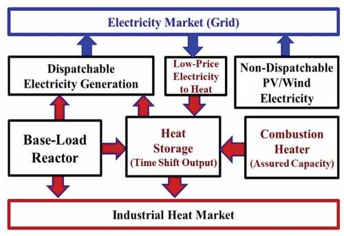
shows the system design for variable electricity and heat with heat storage and assured peak generating capacity coupled to a nuclear reactor.Citation31,Citation32 The same system design is applicable to other heat generating technologies including fossil fuels with CCS, CSP, geothermal, and future fusion machines. To minimize the cost of energy, the nuclear reactor operates at base load. When electricity prices are high, all reactor steam is sent to industry and the turbine to produce electricity. When electricity prices are low, most steam is diverted to heat storage. At times of peak electricity prices, heat from the reactor and heat storage is sent to the turbine for peak electricity production that is significantly above base-load reactor electricity output. Peak electricity production can be achieved by (1) oversizing the turbine generator or (2) building a separate peaking steam turbine for peak power output. At times of very low electricity prices, electricity from the grid and from the main turbine operating at minimum load is converted into stored heat with resistance heaters coupled to the heat storage system. The power plant sells and buys electricity. If heat storage is depleted, natural gas or low-carbon biofuels and hydrogen are used to enable assured peak electricity production by providing the extra heat that would have come from the heat storage system. The same system is used for cogeneration of electricity and heat for industry.
Fig. 10. System design for heat storage coupled to a base-load nuclear reactor for variable electricity and heat
The choice of heat storage technology is dependent upon (1) the exit temperatures of the reactor coolant that must match the storage media and (2) the specific market. A market with large quantities of solar will have large daily variations in electricity prices whereas a market with large quantities of wind will tend to have multiday variations in electricity prices. In most parts of the United States and in many other countries, there is also a large difference in the electrical demand between weekdays and weekends
Heat storage is inexpensive relative to storing electricity. The U.S. Department of Energy (DOE) goal for heat storage capital cost is $15/kW·h(thermal) versus $150/kW·h(electric) for batteries. The cost of the electronics associated with the batteries approximately doubles the cost. shows current Electric Power Research Institute costs for bulk electricity storage systems.
TABLE V Electric Battery Energy Storage Costs for Systems Installed in Fiscal Year 2018*
The cost difference between electricity and heat storage technologies reflects the cost of the raw materials to build the different storage systems. summarizes thermal-heat storage technologies and the upper temperature limits of these technologies. Recent workshopsCitation31,Citation32 have explored the capabilities of these different heat storage systems when coupled to nuclear reactors. The technologies most likely to be used with salt-cooled reactors are described.
TABLE VI Sensible Heat Storage Materials and Maximum Temperature Limits
III.A.1. Liquid Salts
The primary heat storage materials used today in high-temperature CSP systems are nitrate salts with solar salt (60 wt% NaNO3-40 wt% KNO3) the most common salt. Sensible heat of storage is obtained by typically varying temperatures from 290°C to 565°C. With control of gas compositions over the salt storage tanks and salt chemistry, salt storage temperatures of 600°C or more may be viable. CSP salts need reasonable margins from decomposition temperatures to avoid hot spots in solar collectors degrading the salt. These salts are chemically stable in air. Heat storage system capital costs in CSP systems are ~$20/kW·h of heat. The largest storage system sizes are measured in gigawatt hours of capacity. Nitrate salts can be used to move heat to industrial customers.
The typical design of CSP systems with two-tank nitrate salt storage is shown in . Cold nitrate salt is pumped into the CSP system, heated by the sun to 565°C, and sent to the hot storage tank. Storage accomplishes two tasks: (1) enables the solar plant to produce electricity when the sun is down and (2) greatly simplifies operation. On partly cloudy days the power output of a CSP system varies depending on whether the clouds are blocking the sun. With storage, the power block does not see such transients. This greatly simplifies operations.
Fig. 11. System design for CSP and nuclear with heat storage
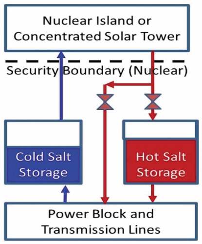
The same nitrate salt storage system designs are proposed for Sodium Fast Reactors (SFRs) (Terrapower), FHRs (Kairos Power), thermal-spectrum MSRs, and fusion machines.Citation2 In addition to providing heat storage, in all of these systems, the low-pressure nitrate salt intermediate loop would provide isolation of the reactor from the high pressures in the power cycle. It replaces the intermediate heat transfer loop in these systems. In SFRs, it avoids the risk of generating hydrogen from a sodium-steam interaction. For FHRs, MSRs, and fusion,Citation2 the salt serves two purposes: (1) heat storage and (2) tritium trapping. These reactor systems generate tritium in the coolant that may diffuse through heat exchangers. If tritium enters a nitrate salt, it is converted into steam that can be collected in the tank off-gas system. Hot nitrate storage acts as a backup tritium removal system.
Different designs of nuclear heat storage systems are evolving. Moltex EnergyCitation34 is proposing that the peak electrical output be three times the base-load nuclear plant capacity based on its analysis of electricity markets in the United Kingdom. Terrapower and others are proposing that only the reactor be inside the security zone with the storage system and power block being outside the security zone. This would dramatically reduce the size of the security zone and enable the remainder of the plant to be built to normal commercial standards with the potential of large economic savings.
Work is underwayCitation35 to develop second-generation salt systems that would allow CSP systems to operate at peak temperatures of ~750°C with higher-temperature stored heat. The goal is to have a pilot plant within 5 years. The proposed salt is a sodium, potassium, magnesium eutectic with a melting point of 383°C. This salt was chosen because of its extremely low cost combined with reasonable physical properties. Allowable peak operating temperatures could exceed 1000°C. The chloride storage salts are proposed to be used with molten chloride fast reactors (Terrapower) with reactor peak temperatures near 750°C. The chloride storage salts would also couple to high-temperature gas-cooled reactors (HTGRs).
III.A.2. Crushed Rock
Crushed rock is the lowest-cost heat storage material; consequently, it is being developed as a heat storage material. Experimental work is underway on a second-generation nitrate heat storage system that would be a single tank filled with crushed rock.Citation36 Hot salt would be on top of cold salt. The addition of crushed rock would replace much of the nitrate salt with much less-expensive crushed rock. The crushed rock would also stabilize the thermocline between the hot salt/rock and cold salt/rock. The use of a single-tank system versus a double-tank system would further reduce costs. The goal is to reduce the capital cost of storage to about $10/kW·h of heat storage in CSP systems.
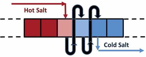
Initial studiesCitation37 are underway on a third-generation nitrate salt–crushed rock system for high-temperature nuclear reactors to further lower capital costs to a few dollars per kilowatt hour of heat storage. The tank structure would be replaced by an insulated trench up to 60 m wide and 20 m high and lengths that may exceed 1000 m with no internal structures. The trench would be filled with crushed rock with approximately 1 GW·h of heat storage for every 10 m in length. The design minimizes structural components and insulation by minimizing the surface-to-volume ratio. The bottom and sides have three layers. Facing the crushed rock is the salt pan that collects salt. It is backed up by insulation with cooling tubes between the insulation and soil to prevent increases in soil temperature, which is a structure similar to the foundation structure for CSP nitrate salt storage tanks. Above the crushed rock is a roof with insulation and salt spray equipment.
The crushed rock is heated by spraying hot salt on top of the rock () to minimize (1) the inventory and thus the cost of nitrate salt and (2) requirements on the rock and the confinement structure. The salt inventory is determined by the maximum rate of heat transfer to and from the crushed rock (megawatts) not by the heat storage capacity (megawatt hours). Hot salt sprayed on a section of rock heats the rock while flowing through the rock to a salt pan at the bottom of the structure. If the salt is not fully cooled, it is collected and sprayed onto the next segment of crushed rock. The rock is heated sequentially from left to right. To heat salt, a traveling wave of salt goes in the reverse direction.
Fig. 12. Sequential heating crushed rock bed with hot salt
There is a parallel effortCitation37,Citation38 to develop hot oil heat storage systems for CSP and nuclear systems. Heat transfer oils have peak temperature limits of ~400°C; consequently, these storage systems are limited to lower-temperature CSP systems and water-cooled reactors. There are operating CSP systems with hot oil storage in tanks. Work is underway to develop systems with crushed rock in the tanks to replace some of the oil inventory and reduce costs. Last, work has begun on crushed rock in large trenches with heat transfer oil to move heat from the CSP/nuclear system to the crushed rock and from crushed rock to the peak power generating system.
III.A.3. Concrete
Low-cost specially formulated concrete is being developed for heat storage at different temperatures. The Westinghouse system consists of thin concrete slabs designed to couple with light water reactors (LWRs) and lead-cooled reactors. Heat is transferred from the reactor coolant to the heat storage system using high-temperature heat transfer oils at atmospheric pressure that can operate up to 400°C; these are the same heat transfer fluids used in many chemical plants and lower-temperature CSP systems. The oil would be heated by steam from the reactor system and then used to heat the concrete at times of low electricity prices. For peak power production, the hot oil would be used for preheating of feedwater. Using stored heat for feed preheating enables peak electricity production 20% to 25% higher than base load. The heat transfer oils are not used for heat storage because of their high cost relative to the low cost of concrete.
Bright Energy is developing a concrete heat storage system that consists of helical tubes in special concretes capable of temperatures in excess of 600°C. The base-line design has steam in the tubes, but other fluids could be used. When steam is added, it heats long concrete modular units from one end to the other while the steam is converted to water. To recover the heat, water is sent in the reverse direction to produce high-temperature steam. This system will couple to any steam power cycle. The initial market is for retrofit to existing coal plants with multiple boilers into peak electricity production systems. If the plant had three boilers, two can be shut down. Heat storage enables one boiler to operate at near full load to produce electricity and charge the heat storage system. At times of peak electricity demand, heat from storage is used to provide steam to operate the steam turbines of the other two units.
III.A.4. Cast Iron with Cladding
Sensible heat can be stored in solid tightly packed hexagonal assemblies 10 to 20 m high made of cast iron with a stainless steel cladding chosen for chemical compatibility to match the coolant, i.e., sodium, salt, lead, or helium. Coolant flows between the solid assemblies. This option places an upper limit on the cost of heat storage associated with any coolant, i.e., water, salt, sodium, and helium. It is compatible with any reactor coolant with the appropriate choice of clad.
III.A.5. Other Options
There are several classes of thermochemical systems where heat is stored in chemical bonds. In hydride systems heat is used to decompose a hydride-producing hydrogen. When the reaction is reversed, the formation of hydride releases heat. In carbonate systems the chemical reaction is conversion of a carbonate such as calcium carbonate into calcium oxide and carbon dioxide. Last, there is a set of chemical reactions that involves forming hydrates where steam is released when the hydrate is heated and heat is generated in the reverse direction. All of these systems are at much earlier stages of development.
III.B. Addressing Low-Carbon Requirements
compares the different systems: wind and solar, nuclear, and combined systems; defines an all wind/solar system; and defines a combined system. The combined system, with local variations in quantities of different energy sources, is the low-cost system because of four factors:
Electricity (kW·h): In good locations, wind and solar provide lower-cost electricity but are available only when wind is blowing and the sun is shining.
Storage: Storage of heat is much less expensive than storing electricity. Heat storage costs will always be lower than electricity storage costs because of the lower cost of raw materials. Storage costs decrease as reactor temperatures increase. For latent heat storage systems (salt, crushed rock, etc.), storage costs decrease as reactor temperatures go up because of the larger swing in hot to cold temperatures. If the temperature swing doubles (LWR to salt-cooled reactor), the quantity of storage material per kilowatt hour of heat is reduced by a factor of 2. Equally important is if heat is stored at high temperature, the heat-to-electricity efficiency is higher, which reduces the cost of heat storage and the cost of the heat-to-electricity conversion system.
Assured peaking capacity (kW): Assured peaking capacity is less expensive for the nuclear systems. With wind and solar systems, one may buy 3 kW of capacity (wind/solar, battery storage, backup gas turbine) for every kilowatt of assured generating capacity (). In this system (), 1 kW of generator capacity (base load and peak) is 1 kW of total capacity. The cost of the backup boiler or furnace for assured peak power is much less than a gas turbine.Citation39
Cogeneration: Nuclear energy produces heat, which is required for industry. The same system including the heat storage systems allows efficient coupling of the energy demands of the electric sector and the industrial sector that allows trade-offs between the two sectors to reduce total energy costs.
TABLE VII Comparison of Nondispatchable and Dispatchable Low-Carbon Systems
III.C. Hydrogen Production
Hydrogen production could potentially be 10% to 30% of the total energy system. It has three roles. The first is as a chemical reagent in the production of fertilizer, metals, and biofuels. In these applications there are no substitutes. The second role is in fuel cells for electricity production for vehicle transport and other purposes. The third role is as a high-temperature heat source for industry and possibly other markets. There are four hydrogen production optionsCitation40:
Steam methane reforming: High-temperature steam is reacted with natural gas to produce hydrogen and carbon dioxide. The carbon dioxide can be sequestered underground.Citation26,Citation41 The process produces a concentrated carbon dioxide stream and a second stream from the burning of natural gas to produce heat for the process; thus, partial CCS can be inexpensive. The United States currently produces 10 million tons of hydrogen primarily for fertilizer production and refining of crude oil. Almost all of this hydrogen is produced by SMR. In a low-carbon world, this becomes the low-cost hydrogen production option where there is inexpensive natural gas and sequestration sites, such as in Texas.
Electrolysis: Water is electrolyzed to produce hydrogen and oxygen. This is an old process used at remote sites to produce smaller quantities of hydrogen.
High-temperature electrolysis (HTE): This is electrolysis of steam and is potentially a lower-cost process than electrolysis because (a) some of the energy is in the form of lower-temperature heat and (b) the process does not require expensive catalysts as used in traditional electrolysis. It is in the early stages of commercialization and would couple to NPPs (see below).Citation42
Thermochemical hydrogen production: In these processes water is converted to oxygen and hydrogen via a series of chemical reactions requiring the input of high-temperature heat. These processes are in the laboratory stage of development.
For hydrogen production SMR has a major advantage over all processes starting with water. Hydrogen is in a chemically reduced form in methane (CH4) whereas with all the other processes, hydrogen is in its oxidized form, i.e., water (H2O). It takes less energy to get hydrogen from methane than water. It is the economic production option in locations with low natural gas prices and good carbon sequestration sites.
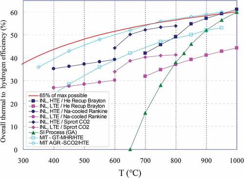
High-temperature electrolysis has major economic advantages over low-temperature electrolysis (LTE) but is at an earlier stage of development. Part of the energy input is in the form of steam that costs less than electricity. If there is very low-price electricity, there is the option of increasing hydrogen production but with lower efficiency. Second, HTE is more efficient than LTE (CitationRef. 43). (CitationRefs. 44 and Citation45) shows the expected efficiencies of converting heat into electricity for LTE and HTE for different reactor systems at different temperatures. For any reactor, there is the choice of (1) converting all the heat to electricity and then producing hydrogen using LTE or (2) converting some of the heat to electricity and supplying the HTE with steam and electricity. This second option produces about a third more hydrogen for the same amount of heat from the reactor.
Fig. 13. Overall thermal-to-hydrogen efficiencies for LTE and HTE versus temperature for different reactor systems (INL = Idaho National Laboratory)
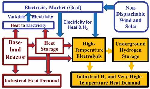
Hydrogen is a premium energy carrier like electricity, but unlike electricity, it can be inexpensively stored in the same underground storage facilities used for natural gas on an hourly to seasonal basis. shows the equivalent systems design for nuclear HTE hydrogen production. Hydrogen storage partly replaces the role of heat storage in a system that can buy and sell electricity from the grid. At times of low electricity prices, electricity from the grid is used for electrolysis while heat from the NPP goes into heat storage and providing steam for the HTE system. At times of high electricity prices, heat from the reactor and heat storage produce peak electricity with no hydrogen production. This system configuration uses heat storage and hydrogen storage for a base-load NPP with variable heat, electricity, and hydrogen output.
Fig. 14. Nuclear hydrogen production system using HTE and heat storage
A nuclear hydrogen electricity production facility allows the option of buying electricity from the grid with more steam and less electricity from the reactor. Dumping low-price electricity into hydrogen production produces a high-value product rather than dumping low-price electricity into heat storage. HTE systems have the capability to produce more hydrogen with higher voltages but at lower efficiency. This creates the option to vary hydrogen production depending upon the price of electricity, adsorbing more excess electricity. A similar systemCitation46 is being developed in Japan for nuclear hydrogen systems coupled to thermochemical hydrogen production with variable electricity to the grid.
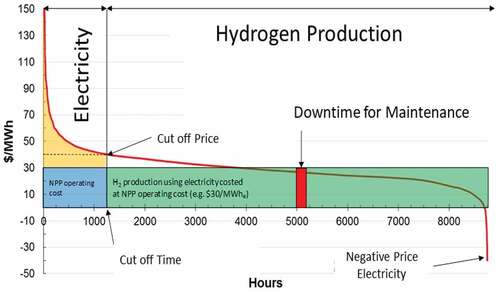
As discussed earlier (), hydrogen production facilities are capital intensive. It is uneconomic to operate such facilities at low capacity factors. This may require that NPPs producing hydrogen operate the hydrogen production facilities more than 80% of the time,Citation47 i.e., the times at which electricity prices are low. Electricity is sold to the grid only at times of high prices. In effect, a nuclear electric hydrogen plant becomes, in terms of the electricity grid, a peaking plant as shown in for peak assured electricity production. This system has the potential to efficiently address seasonal peak demands for electricity (). Large-scale seasonal hydrogen storage is inexpensive (the same technology used for natural gas); thus, at the same time, hydrogen supplies for customers can be assured.
Fig. 15. Hydrogen electricity production strategy
IV. TECHNOLOGY CHOICES AND POWER CYCLE OPTIONS FOR SALT-COOLED REACTORS
The historical market for nuclear power has been base-load electricity. The new market for nuclear energy is variable heat and electricity with assured peak energy production capabilities. The systems to meet these requirements, as described in Sec. III, work with any type of power reactor. However, there are differences in costs depending upon the reactor type because different reactors deliver heat to these systems at different temperatures. The ideal system has several characteristics:
Large peak–to–base-load capacity: If one is to maximize use of low-cost wind and solar electricity where available, one needs nuclear systems that can provide low-cost assured peak capacity that may match the peak electricity demand of the grid if peak demand occurs at times of minimum wind and solar. In northern climates with heating loads, this becomes a real possibility.
Low-cost heat storage: The stored heat capacity per unit mass depends upon the hot-to-cold temperature swing. If one doubles the hot-to-cold swing, storage costs drop in half. Higher-temperature storage lowers heat storage costs.
Efficient fuel-to-electricity conversion: To provide assured backup in the event heat storage is depleted, a combustion heater or boiler is used. In a low-carbon system, the fuel would likely be hydrogen or biofuels. Economics favors power systems with high temperatures and thus high efficiency in converting combustible fuels to electricity. Similarly, if heat is stored at higher temperatures, less storage is required per unit of electricity that is produced.
High-temperature heat for industry: Industry requires high-temperature heat. Increased reactor coolant temperatures implies that a larger fraction of industrial heat demand (including hydrogen production) can be met with nuclear reactors.
Given the above goals, this section describes the technology and power cycle options for salt reactors that deliver all heat above 500°C. Two power cycles with heat storage are described: (1) steam (Rankine) cycles that are the near-term option and (2) nuclear air-Brayton combined cycles (NACCs). Either can be integrated into hydrogen peak electricity production options.
IV.A. Steam (Rankine) Cycles
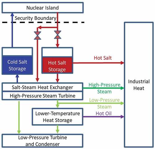
shows a generic design of a high-temperature steam cycle coupled to a salt reactor with storage in multiple locations and capable of providing heat to industrial customers at various temperatures. Nitrate or chloride heat storage is located before the steam cycle with the option to provide heat to industry as hot nitrate or chloride salt. Hot salt can be sent to a steam generator to produce high-temperature high-pressure steam for the high-pressure turbine or industrial customers. After the steam goes through the high-pressure turbine, it can be sent to heat storage, a low-pressure turbine for electricity production, or industry.
Fig. 16. Heat storage options for Rankine cycles with heat to industry
IV.A.1. Salt Heat Storage
Most companies that are developing salt reactor systems have chosen to include an intermediate nitrate salt loop between the reactor and power cycle. The intermediate loop provides isolation between the low-pressure salt reactor and high-pressure power cycle as well as heat storage.
Today, the preferred salt is the sodium-potassium nitrate salts used for heat storage in concentrated solar power plants. This enables using the commercial nitrate heat storage and steam power cycles used in existing CSP plants, thus minimizing development risks associated with the power cycle. Some commercial CSP plants have backup steam boilers to provide assured generating capacity if heat storage is depleted, which is an option available for salt nuclear systems.
IV.A.2. Intermediate-Temperature Heat Storage
Many fossil fuel cogeneration plants produce high-temperature steam, send the steam through a high-pressure turbine producing electricity, and then use the lower-pressure steam as a heat source for lower-temperature industrial processes. The same option applies to salt reactors that produce high-temperature steam. Much of the industrial heat demand is for saturated steam where setting the steam pressure provides constant temperature heat via steam condensation. This includes many processes for production of organic chemicals and biofuels where higher temperatures cause organics to decompose.
Heat storage can be installed between the high-temperature and low-temperature turbines to provide assured steam to industry and variable electricity to the grid. At times of low electricity demand, heat is dumped to storage whereas the low-pressure steam is used for electricity production at times of high electricity demand. Because saturated steam is produced by some CSP systems, multiple heat storage technologiesCitation31 have been developed to operate at these temperatures. Work is underway to couple large-scale heat storage to LWRs at these same temperatures.
The leading heat storage options at the temperatures of saturated steam use high-temperature heat transfer oils and a secondary heat storage medium. The chemical industry has used heat transfer oils for over 50 years that are stable to about 400°C. These oils have low vapor pressures, thus minimizing the risk of fire. These same oils are used in lower-temperature CSP systems. These heat transfer oils have historically been used to transfer heat over long distances in large chemical plants via low-pressure pipelines; thus, such heat storage systems easily couple to industrial customers.
The KoreansCitation38,Citation48–52 are examining a system using heat transfer oils where the heat storage material is crushed rock. There would be multiple tanks of crushed rock with heat transfer oil only in tanks where heat is being transferred from the steam cycle to the crushed rock or from the crushed rock back to the steam cycle. Round-trip efficiencies can approach 80%; that is, if a megawatt hour is generated without storage, 0.8 MW·h of electricity is generated from the stored heat. The Korean design proposes that the storage system be built as a large barge (60 × 450 m) with multiple tanks with a heat storage capacity of 20 GW·h of electricity. This barge is the same size as a supertanker and would be delivered to coastal nuclear power sites where it would be floated into (effectively) a dry dock at the reactor site. When decommissioned, it would be sent back to the shipyard for decommissioning.
IV.B. Nuclear Air-Brayton Combined Cycles
Molten Salt Reactors were originally developed in the late 1950s as part of the U.S. Aircraft Nuclear Propulsion Program that had as its goal a jet-powered bomber of unlimited range to deliver nuclear weapons to the Soviet Union. The reactor was chosen based on its ability to efficiently couple to a jet engine, i.e., a Brayton power cycle. In a jet engine, air is compressed, heated, and exhausted through a turbine that powers the compressor. That requires a reactor that delivers all of its heat at high temperatures significantly above the temperature of the compressed air. In modern gas turbines, that compressed air temperature is above 400°C. Salt reactors efficiently couple to Brayton power cycles with all heat delivered significantly above 400°C.
In the last 60 years, there have been revolutionary advances in gas turbines for electricity production. These advances enable gas turbine combined cycle (GTCC) plants with heat-to-electricity efficiencies above 60%. This enables NACC plantsCitation53 with heat storage and thermodynamic topping cycles. shows NACC (CitationRefs. 1, Citation32, Citation54, Citation55, and Citation56) with a thermodynamic topping cycle and integrated heat storage. The power cycle is similar to a GTCC plant. Research on NACC power cycles is just beginning. These cycles are not viable for lower-temperature LWRs. Like the steam cycle, there is the option of heat storage between the reactor and the power cycle as well as heat storage inside the power cycle.
Fig. 17. Nuclear air Brayton cycle (NACC) with thermodynamic topping cycle and heat storage
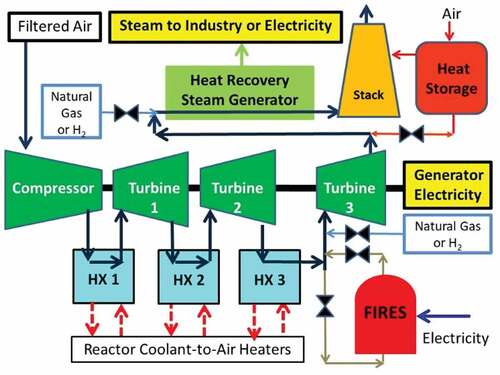
The reactor operates at base load. Within NACC, air is filtered, compressed, heated in heat exchanger 1 (HX1), goes through turbine 1, is reheated in heat exchanger 2 (HX2), goes through turbine 2, is reheated in heat exchanger 3 (HX3), goes through turbine 3, and exits to the steam cycle. The system can have two or three reheat cycles. The warm air from the Brayton cycle goes through the heat recovery steam generator (HRSG) and up the stack. Steam produced in the HRSG can be used to produce electricity or sent to industry. In base-load operation, this system is similar to a GTCC where air temperatures exiting the Brayton cycle are typically near 565°C, as would be if coupled to a salt reactor
For peak electricity production, the hot air exiting HX3 can be further heated by injecting natural gas, biofuels, hydrogenCitation57,Citation58 into the warm compressed gas or by adding high-temperature stored heat in a Firebrick Resistance Heated Energy Storage (FIRES) system before entering turbine 3. The peak temperature limits of modern turbines are far beyond the temperature limits of the heat exchangers between the reactor and the power cycle. shows the nominal projected performance of this system for different reactor heat input temperatures and different peak gas turbine temperatures assuming existing gas turbine technology. Only the last turbine can be used for peaking power because if one adds incremental heat before turbine 1 or turbine 2, the gas temperatures exiting these turbines into exchangers 2 and 3 will be above the reactor coolant temperatures.
TABLE VIII Performance of Different NACC Cycles
In this specific example, it is assumed that hydrogen is used to provide peak electricity with incremental heat-to-electricity efficiencies between 71% and 75%, far above the natural gas–to–electricity efficiency of existing GTCC systems (~63%) and a higher incremental heat-to-electricity efficiency than any other heat engine. The four cases that are shown in include two cases for sodium-cooled reactors and two cases for salt-cooled reactors. This range of temperatures includes salt reactors with and without a nitrate or chloride salt intermediate loop with heat storage. Two peak turbine temperatures are shown for each NACC design. The first is for uncooled turbine blades. The second is for cooled turbine blades used in high-performance GTCC systems.
The overall NACC plant efficiencies when producing peak power with internally cooled turbine blades are near 60% and similar to current GTCCs except low-cost uranium fuel provides the heat at lower temperatures and lower efficiency while a higher-cost fuel (natural gas, hydrogen, biofuels, and stored heat) provides the higher-temperature heat for the thermodynamic topping cycle with higher efficiency.
Thermodynamic topping cycles are not a new concept. The Indian Point Unit I NPP in the United States was a pressurized water reactor that produced saturated steam that was then superheated with an oil-fired superheater before the steam went to the steam turbine. When that plant was built, it had the highest incremental heat-to-electricity efficiency of any oil-fired system. The lower-temperature heat was provided by nuclear heat, and the higher-temperature heat was provided by oil. This has large economic implications in systems that include existing natural gas–fired GTCCs. If a NACC system coupled to a nuclear reactor is added, it is the first “natural gas plant (NACC peaking mode)” to come on-line and the last to go off-line because it burns natural gas much more efficiently than conventional GTCC systems. In a low-carbon system where low-carbon biofuels or hydrogen are the combustible fuels, it becomes the preferred technology to burn these fuels for peak power.
The thermodynamic topping cycle increases the NACC output. For the first case in , if the power output is 1 MW, operating the peaking cycle increases the Brayton cycle output by 46.4% (relative factor of 1.464), and the total plant output increases by 152.2%. Other designs allow much higher peak-to-base power outputs. The incremental capital cost for this peak power producing capability is very low, oversizing the last gas turbine and the HRSG and its steam turbine with associated electric generators.
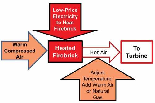
Nuclear air-Brayton combined cycles can incorporate heat storage in several locations in addition to the option of heat storage between the reactor and NACC. Peak power can be produced using the FIRES system where low-price electricity is used to electrically heat firebrick to very high temperatures. For peak electricity production, compressed air is diverted after HX3 into FIRES, directly heated by the firebrick, and then sent to turbine 3. FIRES is inside a pressure vessel. Only firebrick is capable of withstanding the high temperatures required to match gas turbine combustion temperatures. FIRES () is a new heat storage technology under development at the laboratory stage that converts excess low-price electricity into high-temperature stored heat for industrial use or power cycles.Citation39,Citation59,Citation60 Gas temperatures from FIRES can be adjusted by adding either warm compressed air to reduce peak temperatures or supplemental combustion fuels to raise temperatures.
Fig. 18. FIRES for gas turbine system
In electricity systems with large capacities of wind or solar photovoltaic generation, excess electricity is produced at times of high wind or solar output. Coupling FIRES and NACC enables storing this electricity as high-temperature heat for peak power production, effectively operating as an electric battery. The round-trip efficiency is greater than 70% because the electricity-to-heat efficiency is near 100% and the incremental peaking heat-to-electricity efficiency can be as high as 75%. This system has two potential advantages over batteries and other electricity storage systems. First, the capital cost—heat storage plus the incremental added cost for peaking capability in the gas turbine—is expected to be less. Second, if heat storage is depleted, assured peak electricity production is still possible by burning natural gas, hydrogen, or biofuels. With batteries and other electricity storage technologies, a separate gas turbine must be added to the system to provide assured generating capacity if electricity storage is depleted.
Second, heat exhausted from gas turbine 3 at times of low electricity demand can be diverted from the HRSG to a heat storage recuperator (red) using firebrick, concrete, crushed rock, or other storage medium and then up the stack. At times of high electricity demand, cold air can be blown through the hot recuperator in the reverse direction to provide hot air to the HRSG in addition to the hot air from turbine 3 for peak electricity production. The cost of this heat storage system is low because these heat storage systems operate at low pressure and lower temperatures than the gas turbine. If the heat recuperator storage system is depleted, assured peak generating capacity can be provided with a combustible fuel to provide heat to the boiler.
There is ongoing workCitation61–64 to develop heat storage for GTCC systems. Combined cycle plants have efficiencies over 60% versus simple gas turbines with efficiencies of ~40%. By including heat storage in CGCC systems between the gas turbine and HRSG, the combined cycle plant can vary electricity output over a much larger range while maintaining the higher efficiency of the GTCC system.
IV.C. Hydrogen and Peak Electricity Production
In any low-carbon future, hydrogen will be a major chemical reagent and energy carrier. It will be a commodity like electricity except it is storable on an hourly to seasonal basis. This is why some hydrogen projections such as the Shell SKY scenarioCitation65 show hydrogen as a major energy carrier, i.e., 800 million tons by 2040 versus 70 million tons today. Current hydrogen production uses 6% of global natural gas consumption and 2% of global coal production.Citation66
Such hydrogen futures create the option of NPPs with HTE operating more than 80% of the year producing hydrogen and producing peak assured electricity when most needed, at the scale to address the seasonal peak demand for electricity. Salt reactors have two advantages for this system:
Efficient hydrogen production: The high-temperature heat output enables more hydrogen production per unit of heat input.
Efficient peak power production: The NACC power cycle in peaking mode enables (a) a very large peak–to–base load output using a low-capital-cost gas turbine power cycle and (b) very efficient incremental heat-to-electricity production. In a low-carbon world hydrogen may be the storable combustible fuel, but it is a premium fuel because electricity is a major input in its production. NACC is the most efficient method to convert hydrogen to peak electricity, more efficient than a stand-alone GTCC or fuel cell.
IV.D. Economics
Historically, it has been assumed that there are significant differences in the costs of different reactor types. Recent reportsCitation13 have come to the conclusion that the costs of different reactor types are similar. The costs of design, licensing, and other indirect costs far exceeded the material cost differences among reactor types. In a low-carbon world with large changes in markets, the economics of different nuclear systems depends upon differences in revenue. That, in turn, depends upon the power system costs for storage and assured peak generating capability. Those power system costs favor the reactors with the highest average temperature of delivered heat, i.e., salt-cooled systems. The production of hydrogen has similar incentives to use higher-temperature reactors.
V. CONCLUSIONS
Global energy systems are undergoing two changes: (1) the development of nondispatchable wind and solar with low LCOE in some locations and (2) the goal of a low-carbon energy system. It is in this context one must rethink the requirements for nuclear energy and what types of reactors will be economically most competitive:
Markets: The goal of a low-carbon world requires a replacement for fossil fuels in their role of providing variable electricity and heat. Separately, the large-scale addition of wind and solar creates highly volatile wholesale electricity prices with times of very low and high prices. The largest market is heat, not electricity.
Requirements: The top-level requirements for a nuclear system in a low-carbon world or a world with large-scale wind and solar are to provide variable heat and electricity with assured peak energy production capacity. This will require either low-cost nuclear reactors operating at variable load or base-load nuclear reactors with large-scale heat storage and the capability to provide assured peak energy production capacity.
Industry energy options: To be economically competitive, industry with massive heat demands will require either heat from nuclear reactors or locating industry near sites that allow continued use of fossil fuels with CCS. Higher-temperature reactors enable a larger fraction of total industrial heat demand to be met with nuclear heat versus electricity or hydrogen. The efficiency of nuclear hydrogen production increases with higher temperatures.
System design: To address the changing markets, new reactor system designs are required. For the electric sector this includes reactors with large-scale heat storage and assured peak electricity production. This system design can also provide industrial heat while coupling the electric and industrial sectors to minimize total cost of energy. The other set of alternatives is nuclear hydrogen peak-electricity systems with large-scale hydrogen storage. This option converts nuclear energy into a system to produce (a) hydrogen and (b) electricity to meet peak seasonal electricity demands. With all of these options, the reactor is designed to operate at base load.
Reactor choices: Other factors being equal, there are large economic advantages in coupling salt-cooled reactors with higher average temperatures of delivered heat versus other types of reactors to power systems with heat storage and assured peak energy production capacity. HTGRs have many but not all of the advantages of salt-cooled reactors for meeting these goals. High-temperature heat is what industry requires. The higher average temperature of delivered heat to the power cycle significantly reduces the cost of (a) heat storage systems and (b) assured peak energy production capacity. Higher temperatures enable NACC cycles with high-efficiency peaking capabilities and more efficient hydrogen production in systems designed to produce hydrogen and peak electricity.
Geographical energy markets: Fossil fuels enabled a world of flat energy prices where the cost of coal, oil, or LNG is about the same in New York Harbor as Shanghai Harbor. The economics and viability of solar, wind, hydro, and fossil fuels with CCS are location dependent. Nuclear energy is the only low-carbon energy source where the costs and technical viability are not dependent upon local conditions. The ability to limit variations in energy costs with location (and thus the standard of living with location) depends upon success in minimizing the cost of nuclear energy systems that can provide variable electricity and heat.
Last, most of industry and most of the energy infrastructure were developed for use with fossil fuels. Going to a low-carbon system implies major changes in industrial processes to (1) use alternative energy sources (electricity, hydrogen, nuclear heat) or (2) produce concentrated carbon dioxide steams for CCS. Similar transformations must occur in the transport sector. While the broad outlines of future energy systems can be developed, the changes in the form of energy (electricity, heat, hydrogen) required by the customers (residential, commercial, industrial, and transportation) and quantities required are highly uncertain.
Acknowledgments
This work was supported by the Shanghai Institute of Applied Physics (SINAP) of the Chinese Academy of Sciences and the DOE. I would like to thank the following individuals for providing information and reviews: M. Driscoll (MIT), W. J. Nuttall (The Open University, United Kingdom), J. E. O’Brien (Idaho National Laboratory) and J. Lassiter [Harvard University (retired)].
References
- C. ANDREADES et al., “Design Summary of the Mark-I Pebble-Bed, Fluoride Salt-Cooled, High-Temperature Reactor Commercial Power Plant,” Nucl. Technol., 195, 3, 223 (2016); https://doi.org/10.13182/NT16-2.
- C. FORSBERG et al., “Fusion Blankets and Fluoride-Salt-Cooled High-Temperature Reactors with Flibe Salt Coolant: Common Challenges, Tritium Control, and Opportunities for Synergistic Development Strategies Between Fission, Fusion and Solar Technologies,” Nucl. Technol., 206, 1778 (2020); https://doi.org/10.1080/00295450.2019.1691400.
- Molten Salt Reactors and Thorium Energy, T. J. DOLAN, Ed., Elsevier (June 2017); https://www.elsevier.com/books/molten-salt-reactors-and-thorium-energy/dolan/978-0-08-101126-3 (current as of Dec. 12, 2019).
- R. PETROSKI and L. WOOD, “Sustainable, Full-Scope Nuclear Fission Energy at Planetary Scale,” Sustainability, 4, 3088 (2012); https://doi.org/10.3390/su4113088.
- “Energy Flow Charts,” Lawrence Livermore National Laboratory (2020); https://flowcharts.llnl.gov/commodities/energy ( 2018) ( current as of Dec. 12, 2019).
- “In 2016, U.S. Energy Expenditures per Unit GDP Were the Lowest Since at Least 1970,” in “Today In Energy,”Monthly Energy Review and State Energy Data System, U.S. Information Agency; https://www.eia.gov/todayinenergy/detail.php?id=36754 ( current as of Dec. 12, 2019).
- “Lazard’s Levelized Cost of Energy Analysis—Version 12.0” (Nov. 2018); https://www.lazard.com/media/450784/lazards-levelized-cost-of-energy-version-120-vfinal.pdf ( current as of Dec. 12, 2019).
- “Nuclear Energy and Renewables: System Effects in Low-Carbon Electrical Systems,” NEA 7056, Organisation for Economic Co-operation and Development Nuclear Energy Agency; https://www.oecd-nea.org/ndd/pubs/2012/7056-system-effects.pdf ( current as of Dec. 12, 2019).
- V. SIVARAM and S. KANN, “Solar Power Needs a More Ambitious Cost Target,” Nat. Energy, 1, 16036 (Apr. 2016); https://doi.org/10.1038/nenergy.2016.36.
- J. BUSHNELL and K. NOVAN, “Setting with the Sun: The Impacts of Renewable Energy on Wholesale Power Markets,” DEEP WP 020, UC Davis Energy Economics Program (May 2018); http://deep.ucdavis.edu/uploads/5/6/8/7/56877229/deep_wp020.pdf (current as of Dec. 12, 2019).
- R. SCHMALENSEE et al., “The Future of Solar Energy: An Interdisciplinary MIT Study,” Massachusetts Institute of Technology (2015); https://energy.mit.edu/wp-content/uploads/2015/05/MITEI-The-Future-of-Solar-Energy.pdf (current as of Dec. 12, 2019).
- A. D. MILLS et al., “Impact of Wind, Solar, and Other Factors on Wholesale Power Prices: An Historical Analysis—2008 Through 2017,” Lawrence Berkeley National Laboratory (Nov. 2019); https://eta-publications.lbl.gov/sites/default/files/lbnl_-_wind_and_solar_impacts_on_wholesale_prices_approved.pdf (current as of Dec. 12, 2019).
- J. BUONGIORNO et al., “The Future of Nuclear Energy in a Carbon Constrained World,” Massachusetts Institute of Technology (2018); http://energy.mit.edu/wp-content/uploads/2018/09/The-Future-of-Nuclear-Energy-in-a-Carbon-Constrained-World.pdf (current as of Dec. 12, 2019).
- N. SEPULVED et al., “The Role of Firm Low-Carbon Electricity Resources in Deep Decarbonization of Power Generation,” Joule, 2, 11, 2403 (Nov. 21, 2018); https://doi.org/10.1016/j.joule.2018.08.006.
- J. BISTLINE, R. JAMES, and A. SOWDER, “Technology, Policy, and Market Drivers of (and Barriers to) Advanced Nuclear Reactor Deployment in the United States after 2030,” Nucl. Technol., 205, 8, 1075 (2019); https://doi.org/10.1080/00295450.2019.1574119.
- K. D. TAPIA-AHUMADA et al., “Deep Decarbonization of the U.S. Electricity Sector: Is There a Role for Nuclear Power,” Report 338, Massachusetts Institute of Technology Joint Program on the Science and Policy of Global Change (Sep. 2019); https://globalchange.mit.edu/sites/default/files/MITJPSPGC_Rpt338.pdf (current as of Dec. 12, 2019).
- E. J. MONIZ et al., “The Future of Natural Gas,” Massachusetts Institute of Technology (2011); http://energy.mit.edu/wp-content/uploads/2011/06/MITEI-The-Future-of-Natural-Gas.pdf (current as of Dec. 12, 2019).
- S. J. DAVIS et al., “Net-Zero Emissions Energy Systems,” Science, 360, eaas9793 (2018); https://doi.org/10.1126/science.aas9793.
- W. H. GREEN et al., “Insights into Future Mobility,” Massachusetts Institute of Technology (2019); http://energy.mit.edu/wp-content/uploads/2019/11/Insights-into-Future-Mobility.pdf (current as of Dec. 12, 2019).
- A. BEDIR et al., “Staff Report – California Plug-In Electric Vehicle Infrastructure Projections 2017-2025,” CEC-600-2018-001, California Energy Commission (Mar. 2018); https://www.nrel.gov/docs/fy18osti/70893.pdf). (current as of Dec. 12, 2019
- B. DALE et al., “Take a Closer Look: Biofuels Can Support Environmental, Economic and Social Goals,” Environ. Sci. Technol., 48, 7200 (2014); https://pubs.acs.org/doi/pdf/10.1021/es5025433.
- B. E. DALE, “Feeding a Sustainable Chemical Industry: Do We Have the Bioproducts Cart Before the Feedstocks Horse?” Faraday Discuss., 202, 11 (2017); https://doi.org/10.1039/C7FD00173H.
- B. DALE et al., “Biofuels Done Right: Land Efficient Animal Feeds Enable Large Environmental and Energy Benefits,” Environ. Sci. Technol., 44, 8385 (2010); https://pubs.acs.org/doi/pdf/10.1021/es101864b.
- M. HOLTZAPPLE, S. LONKAR, and C. GRANDA, “Producing Biofuels via the Carboxylate Platform,” Chem. Eng. Prog., 111, 3, 52 (Mar. 2015); https://www.researchgate.net/profile/Sagar_Lonkar/publication/284745695_Producing_biofuels_via_the_carboxylate_platform/links/5b94930192851c78c4015785/Producing-biofuels-via-the-carboxylate-platform.pdf?origin=publication_detail (current as of Dec. 12, 2019).
- “Liquid Hydrogen Fuelled Aircraft—System Analysis,” Airbus Deutschland GmbH (2003); https://www.fzt.haw-hamburg.de/pers/Scholz/dglr/hh/text_2004_02_26_Cryoplane.pdf (current as of Dec. 12, 2019).
- W. NUTTALL and A. T. BAKENNE, Fossil Fuel Hydrogen: Technical, Economic and Environmental Potential, Springer (2020).
- “Opportunities for Cogeneration with Nuclear Energy,” NP-T-4.1, International Atomic Energy Agency, (May 2017); https://www-pub.iaea.org/MTCD/Publications/PDF/P1749_web.pdf (current as of Dec. 12, 2019).
- “U.S. DOE Combined Heat and Power Installation Database,” U.S. Department of Energy (2019); https://doe.icfwebservices.com/chpdb/ (current as of Dec. 12, 2019).
- S. J. FRIEDMANN, Z. FAN, and K. TANK, “Low-Carbon Heat Solutions for Heavy Industry: Sources, Options and Costs Today,” Columbia/SIPA Center on Global Energy Policy (Oct. 2019); https://energypolicy.columbia.edu/sites/default/files/file-uploads/LowCarbonHeat-CGEP_Report_100219-2_0.pdf (current as of Dec. 12, 2019).
- L. M. MILLER and D. W. KEITH, “Observation-Based Solar and Wind Power Capacity Factors and Power Densities,” Environ. Res. Lett., 13, 104008 (2018); https://doi.org/10.1088/1748-9326/aae102.
- C. W. FORSBERG, “Variable and Assured Peak Electricity Production from Base-Load Light-Water Reactors with Heat Storage and Auxiliary Combustible Fuels,” Nucl. Technol., 205, 377 (2019); https://doi.org/10.1080/00295450.2018.1518555.
- C. W. FORSBERG, P. SABHARWALL, and H. GOUGAR, “Heat Storage Coupled to Generation IV Reactors for Variable Electricity from Base-Load Reactors,” Workshop Proceedings, ANP-TR-185, Center for Advanced Nuclear Energy, Massachusetts Institute of Technology, INL/EXT-19-54909, Idaho National Laboratory (2019); https://www.osti.gov/biblio/1575201 (current as of Dec. 12, 2019).
- “Energy Storage Cost Analysis: 2017 Methods and Results,” Electric Power Research Institute (2017).
- Moltex Energy website (2020); https://www.moltexenergy.com/ (current as of Dec. 12, 2019).
- M. MEHOS et al., “Concentrated Solar Power Gen3 Demonstration Roadmap,” NREL/TP-5500-67464, National Renewable Energy Laboratory (Jan. 2017); https://www.nrel.gov/docs/fy17osti/67464.pdf (current as of Dec. 12, 2019).
- C. ODENTHAL et al., “Experimental and Numerical Investigation of a 4 MWh High Temperature Molten Salt Thermocline Storage System with Filler,” Proc. 25th Annual SolarPACES Conf., Daegu, Korea, October 1–4, 2019.
- C. W. FORSBERG, “Multi-Gigawatt-Day Low-Cost Crushed-Rock Heat Storage Coupled to Nuclear Reactors for Variable Electricity and Heat,” Trans. Am. Nucl. Soc., 122, 553 (2020); https://doi.org/10.13182/T122-32009.
- K. F. AMUDA and R. M. FIELD, “Proposed Heat Storage and Recovery Facility Designs for Korean Nuclear Power Plants Using Ultra Large Floating Barge,” Transactions of the Korean Nuclear Society Autumn Meeting, Goyang, Korea, October 23–25, 2019.
- C. FORSBERG, S. BRICK, and G. HARATYK, “Coupling Heat Storage to Nuclear Reactors for Variable Electricity Output with Base-Load Reactor Operation,” Electr. J., 31, 23 (Apr. 2018); https://doi.org/10.1016/j.tej.2018.03.008.
- Nuclear Hydrogen Production Handbook, X. L. YAN and R. HINO, Eds., CRC Press (2011).
- N. MURADOV, “Low to Near-Zero CO2 Production of Hydrogen from Fossil Fuels: Status and Perspectives,” Int. J. Hydrogen, 42, 14058 (2017); https://doi.org/10.1016/j.ijhydene.2017.04.101.
- K. FRICK et al., “Evaluation of Hydrogen Production Feasibility for a Light Water Reactor in the Midwest,” INL/EXT-19-55395, Idaho National Laboratory (Sep. 2019).
- B. D. JAMES, D. A. DeSANTIS, and G. SAUR, “Final Report: Hydrogen Production Pathways Cost Analysis (2013–2016),” DOE-StrategicAnalysis-6231-1, U.S. Department of Energy (Sep. 30, 2016); https://www.osti.gov/servlets/purl/1346418 ( current as of Dec. 12, 2019).
- J. E. O’BRIEN et al., “High-Temperature Electrolysis for Hydrogen Production from Nuclear Energy—Technology Summary,” INL/EXT-09-16140, Idaho National Laboratory (Feb. 2010); https://inldigitallibrary.inl.gov/sites/sti/sti/4480292.pdf (current as of Dec. 12, 2019).
- J. E. O’BRIEN, “Thermodynamics and Transport Phenomena in High Temperature Steam Electrolysis Cells,” J. Heat Transfer, 134, 031017–1 (Mar. 2012); https://doi.org/10.1115/1.4005132.
- X. L. YAN and H. SATO, “HTGR and Renewable Hybrid Energy System for Grid Stability – Assessment of Performance, Economics and CO2 Reduction,” Proc. IAEA Technical Mtg. Nuclear–Renewable Hybrid Energy Systems for Decarbonized Energy Production and Cogeneration, Vienna, Austria, October 22–25, 2018, International Atomic Energy Agency (2018).
- R. BOARDMAN et al., “Evaluation of Non-Electric Market Options for a Light-Water Reactor in the Midwest (Light Water Reactor Sustainability Program),” INL/EXT-19-55090, Idaho National Laboratory (Aug. 2019); https://www.osti.gov/biblio/1559965 (current as of Dec. 12, 2019).
- K. F. AMUDA and R. M. FIELD, “Nuclear Heat Storage and Recovery for the APR1400,” J. Storage Mater., 28 (Apr. 2019); https://doi.org/10.1016/j.est.2019.101171.
- A. KLUBA and R. FIELD, “Optimization and Exergy Analysis of Nuclear Heat Storage and Recovery,” Energies, 12, 4205 (2019); https://doi.org/10.3390/en12214205.
- A. M. KLUBA and R. M. FIELD, “Optimization for the Nuclear Heat Storage and Recovery Rankine Cycle,” Transactions of the Korean Nuclear Society Spring Meeting, Jeju, Korea, May 23–24, 2019.
- K. F. AMUDA and R. M. FIELD, “Nuclear Heat Storage and Recovery in a Renewable Energy World,” Transactions of the Korean Nuclear Society Spring Meeting, Jeju, Korea, May 23–24, 2019.
- A. M. KLUBA and R. M. FIELD, “Control System Considerations for APR1400 Integrated with Thermal Energy Storage,” Transactions of the Korean Nuclear Society Spring Meeting, Goyang, Korea, October 23–25, 2019.
- C. W. FORSBERG, P. J. McDANIEL, and B. ZOHURI, “Nuclear Air-Brayton Power Cycles with Thermodynamic Topping Cycles, Assured Peaking Capacity and Heat Storage for Variable Electricity and Heat,” Nucl. Technol. (2020); https://doi.org/10.1080/00295450.2020.1785793.
- B. ZOHURI and P. McDANIEL, Advanced Smaller Modular Reactors: An Innovative Approach to Nuclear Power, 1st ed., Springer (2019); https://www.springer.com/us/book/9783030236816 (current as of Dec. 12, 2019).
- B. ZOHURI and P. McDANIEL, Combined Cycle Driven Efficiency for Next Generation Nuclear Power Plants: An Innovative Design Approach, 2nd ed., Springer (2018); https://www.springer.com/gp/book/9783319705507 (current as of Dec. 12, 2019).
- B. ZOHURI, P. McDANIEL, and C. R. DE OLIVERIA, “Advanced Nuclear Open Air-Brayton Cycles for Highly Efficient Power Conversion,” Nucl. Technol., 192, 1, 48 (2015); https://doi.org/10.13182/NT14-42.
- M. R. BOTHIEN and A. CIANI, “Sequential Combustion of Hydrogen for Carbon-Free Dispatchable Power Generation from Gas Turbines,” Mech. Eng., 141, 12, 46 (Dec. 2019).
- “Hydrogen-Capable Gas Turbines for Deep Decarbonization,” Electric Power Research Institute (Nov. 2019).
- C. W. FORSBERG et al., “Converting Excess Low-Priced Electricity into High-Temperature Stored Heat for Industry and High-Value Electricity Production,” Electr. J., 30, 42 (July 2017); https://doi.org/10.1016/j.tej.2017.06.009.
- D. C. STACK, D. CURTIS, and C. FORSBERG, “Performance of Firebrick Resistance-Heated Energy Storage for Industrial Heat Applications and Round-Trip Electricity Storage,” Appl. Energy, 242, 782 (2019); https://doi.org/10.1016/j.apenergy.2019.03.100.
- D. LI et al., “Combined-Cycle Gas Turbine Power Plant Integration with Cascaded Latent Heat Thermal Storage for Fast Dynamic Responses,” Energy Convers. Manage., 183, 1 (Mar. 2019); https://doi.org/10.1016/j.enconman.2018.12.082.
- M. K. DROST et al., “Thermal Energy Storage for Integrated Gasification Combined-Cycle Power Plants,” PNL-7403, Pacific Northwest Laboratory (July 1990); https://www.osti.gov/servlets/purl/6624383 (current as of Dec. 12, 2019).
- R. SHINNAR and H. BINDRA, “Thermal Energy Storage for Combined Cycle Power Plants,” WO2012150969A1, World Intellectual Property Organization (2012); https://patents.google.com/patent/WO2012150969A1 ( current as of Dec. 12, 2019).
- “High-Temperature Heat Storage Systems for Flexible CCGT Power Plants,” Kraftwerk Forschung; https://kraftwerkforschung.info/en/high-temperature-heat-storage-systems-for-flexible-ccgt-power-plans/ ( current as of Dec. 12, 2019).
- “Shell Scenarios SKY: Meeting the Goals of Paris Agreement,” Shell Oil Company (2019); https://www.shell.com/promos/business-customers-promos/download-latest-scenario-sky/_jcr_content.stream/1530643931055/eca19f7fc0d20adbe830d3b0b27bcc9ef72198f5/shell-scenario-sky.pdf (current as of Dec. 12, 2019).
- “The Future of Hydrogen: Seizing Today’s Opportunities,” International Energy Agency (June 2019); https://www.iea.org/reports/the-future-of-hydrogen (current as of Dec. 12, 2019).