
 ?Mathematical formulae have been encoded as MathML and are displayed in this HTML version using MathJax in order to improve their display. Uncheck the box to turn MathJax off. This feature requires Javascript. Click on a formula to zoom.
Abstract
Uranium nitride (UN) is considered as nuclear reactor fuel because of, among other reasons, its high uranium density and its high thermal conductivity. Its main drawback is that it relatively easily dissolves in hot water, which is particularly problematic when it is used in water-cooled reactors. One possible remedy to this is to add some corrosion inhibitor as dopant to the UN matrix. A number of dopants have been identified that have the potential to inhibit the dissolution process, and their respective merits have been investigated both by neutronic simulations and dissolution experiments. It is concluded that chromium is the most promising candidate.
I. INTRODUCTION
Uranium nitride (UN) is considered a nuclear reactor fuel because of several inherent properties that make it superior to the currently predominant chemical form of uranium: uranium dioxide (UO2). In particular, the UN lattice has a higher uranium density, which is advantageous from a neutronics perspective, and the thermal conductivity is higher,Citation1,Citation2 slowing down fuel material degrading processes such as cracking and diffusion of fission productsCitation3 as well as providing a larger margin to fuel melting in accident scenarios. Because of these properties, UN is often mentioned as a candidate for the accident tolerant fuels discussed within the nuclear power industry in the aftermath of the Fukushima Daiichi nuclear reactor accident in 2011 (CitationRef. 4).
However, UN is not stable in hot water or steam where it oxidizes through an exothermic reaction. For light water reactor use, this is especially problematic in the case of an accident where the fuel would be exposed to exactly this environment, but it is also problematic in the case of a relatively common occurrence such as cladding failure.
Studies of UN oxidation were already performed in the 1960s (CitationRefs. 5 and Citation6). Uranium nitride behaves as an inert compound in water up to 80°C (CitationRef. 7). Both UN and U2N3 react with water vapor at about 250°C and form ammonia and hydrogen. A protective layer of UO2 can form on the surface of UN causing a partial stability in moist air up to 20°C (CitationRef. 5). However, O2 diffuses through this UO2 layer and reacts on the interface with UO2/U2N3 by releasing nitrogen. A sandwich structure was shown in samples consisting of the UO2 outer layer followed by U2N3 and finally the UN layer.Citation5 Water molecules are bigger than oxygen and cannot diffuse through the UO2 layer but can migrate through pores and cracks in the UO2 layer. OH– ions then react on the interface. Higher oxidation products such as UO3 or U3O8 are formed during oxidation.Citation5,Citation8 A diffusion of nitrogen gas toward the sample surface is a rate-controlling process during oxidation.Citation8
The experiments summarized herein have been previously presented by CitationRef. 9, where it was found that the addition of Cr seemed to stabilize UN during exposure to boiling water. In this paper, we further analyze the process resulting in this stabilization as well as the neutronic rationale for and consequences of using Cr as a dopant for stabilization of UN.
The theory and connected reasoning behind the choice of dopants for investigation are outlined in Sec. II. The methodology and choice of input parameters for the neutronic simulations are described in Sec. III, and the experimental procedure for manufacture and dissolution tests of doped UN fuel pellets are described in Sec. IV. Results of the simulations, manufacture, and dissolution tests are described in Sec. V, and finally, conclusions are drawn in Sec. VI.
II. THEORY
II.A. Oxidation Protection of UN
One method for protecting easily oxidized materials is to add a dopant that forms a stable oxide. A layer of this oxide may then form on the exposed surface, protecting the bulk material from further oxidation. This mechanism is commonly used in the manufacturing of corrosion-resistant alloys, e.g., stainless steels, where chromium is often used as a dopant. The added chromium forms a protective layer of chromium (III) oxide (Cr2O3) on the surface of an iron alloyCitation10 if the alloy consists of more than 5 wt% Cr (CitationRef. 11). Cr2O3 is stable in water over a wide range of pH and low content of dissolved oxygen, which is visualized in the form of a Pourbaix diagram; see .
Fig. 1. A Pourbaix diagram of chromium species at 300°C. A vertical dotted line corresponds to a neutral pH at 300°C. The image is based on data from CitationRef. 10.
The dotted line in indicates a neutral pH at 300°C. In a reactor core the level of dissolved oxygen in water is kept below 5 parts per billion by hydrogen injectionsCitation12 to suppress radiolysis, and the electrochemical potential of water was measured to be between −150 to −100 mV using a standard hydrogen electrode.Citation13 Therefore, a uniform protective layer or multiple layers of Cr2O3 would prevent UN from corrosion under operating conditions in the core.
The same effect of a protective layer could be formed by aluminum oxide (Al2O3) in a pH range from 5 to 7.5, but Al2O3 transforms into [AlO2]− at higher pH (CitationRef. 14). Other metals such as silicon, titanium, tantalum, niobium, or nickel can form a protective oxide layer.Citation11 lists the proposed dopants along with some basic neutronic data for the predominant isotopes, the reaction corresponding to the capture of a neutron by the most abundant isotope of each element, and the cross section for the respective reactions.
TABLE I Proposed Dopants and Basic Neutronic Data from CitationRef. 15
Titanium and tantalum must be excluded from the list due to their high thermal neutron capture cross sections, which would cause an undesired reactivity decrease in the fuel. Silicon has already been extensively researched as an oxidation inhibitor for UN; see, e.g., CitationRefs. 16 and Citation17. Based on these considerations, chromium, nickel, niobium, and aluminum were chosen for further investigation of their properties as dopants.
II.B. Neutronic Properties of UN
The use of UN, which has a 40% higher uranium density than UO2 fuel, allows for a higher average density of U atoms in the reactor core, which opens up possibilities for reactor core designs with increased power density or cycle length. The addition of a dopant reduces this advantage to some extent, and neutronic modeling was performed to assess the importance of this. The simulations were carried out using the continuous-energy Monte Carlo reactor physics burnup calculation code SerpentCitation18 and assuming, for simplicity, a quadratic infinite lattice of cylindrical, zirconium-clad fuel pins. For reference, a UO2 pin cell lattice was simulated, having the dimensions typical for a 17 × 17 rod pressurized water reactor (PWR) fuel assembly. For the simulation of a UN pin cell lattice, however, some factors affecting the optimal fuel pellet radius and pin pitch had to be taken into account, as described below. All simulations were performed assuming the same uranium enrichment of 4.96%.
A potential drawback of UN use is the parasitic neutron capture in 14N. To eliminate this drawback, the used nitrogen may be enriched in 15N, which has a smaller capture cross section. For the current simulations, the nitrogen is assumed to be enriched to 90% 15N.
The optimization of a nuclear reactor core design aims to minimize the amount of fissile material needed to keep the reactor critical for a certain period (a cycle length) at a certain power (prescribed by the reactor’s thermal-hydraulic system). Criticality means that the number of neutrons is constant, which implies that the number of neutrons released by fission events is equal to the number of neutrons that leak out of the system or are absorbed in the fuel, the moderator (in the present case hydrogen, present in the form of light water), or structural materials. The amount of hydrogen in the core affects the fission rate by moderating the neutrons, hence increasing the fission cross section of 235U, but it also affects the absorption rate since neutrons may be captured by the hydrogen atoms. Hence, the hydrogen–to–heavy metal (H/HM) ratio needs to be optimized to balance these effects. One also needs to take into account that the core must have some margin to being overmoderated (have a too high H/HM ratio) since this would result in a negative moderator density coefficient, i.e., increased reactivity at an increase in the moderator temperature that would lead to a positive feedback loop and thus an unstable core.
If UN is used in a standard fuel assembly design, optimized for the use of UO2, the core will be undermoderated. This results in a harder neutron spectrum and hence an increased conversion rate of 238U into 239Pu at the cost of the fission rate in 235U, i.e., a decreased initial reactivity. The consequences of this have been investigated previously.Citation19
If, instead, the water volume is increased relative to the fuel volume so that the H/HM ratio is kept at an optimal value, i.e., equal to that of an optimized UO2 lattice, the initial reactivity becomes higher than that of the UO2 lattice due to the higher lattice-average concentration of U. Since the balance between fission and conversion reactions is similar to that of the optimized UO2 lattice (due to the similar moderation), the rate of decrease in reactivity is also similar, so starting at a higher initial reactivity means that the reactor can stay critical for a longer time. The required adjustment of the H/HM ratio can, in this case, be achieved by simply increasing the lattice pin pitch.
The reactivity dependence on the moderation conditions is illustrated in , where it can be seen that the curves for the adjusted UN (“Adjusted UN”) and UO2 (“Reference UO2”) lattices with similar H/HM ratios are parallel, with the UN lattice starting at a higher value. The
curve of an undermoderated UN lattice (“Reference UN”) is also shown, demonstrating the slower reactivity decrease resulting from the higher conversion and lower fission rate.
Fig. 2. The value as a function of time, assuming an equal power density of 100 kW/L for all cases. The reference lattice has dimensions typical for a PWR fuel assembly, whereas the adjusted lattice has a higher H/HM ratio.
The pin pitch of the modified UN lattice was calculated using Eq. (1) in order to achieve the same H/HM ratio as in the reference UO2 lattice:
The interpretation and used values of the parameters in Eq. (1) are listed in . All material properties in are stated for a temperature of 800 K. Gap width and cladding thickness were assumed equal for all cases.
TABLE II Used Parameters for the Simulated Pin Cell Lattices
It should also be noted that it may be desirable or required to make further adjustments of the fuel dimensions in order to accommodate for the lower heat capacity of UN compared with UO2; see . The lower heat capacity results in a more rapid response to, e.g., a reactivity insertion, as shown in CitationRef. 25. This may result in instability although it also gives benefits in terms of a smaller local heat deposition during the transient. A possible remedy is a larger rod size, which is also warranted by the higher thermal conductivity, also listed in . It is noted that both the thermal conductivity and the volumetric heat capacity
of the UN fuel material are expected to decrease when a dopant is added. The extent of this decrease is however yet unknown.
shows that the UN fuel with the reference fuel assembly design gives a higher reactivity than the UO2 fuel assembly after about 400 days, indicating that a longer cycle length should be possible than with the UO2 fuel assembly, which is in line with the findings presented in CitationRef. 19. The modified lattice, however, gives a significantly higher reactivity during the entire simulated period, which is an advantage that could be capitalized on in terms of longer cycle lengths (as in ), higher power density (which would mean a steeper slope of the curve), or lower enrichment costs (which would mean a lower starting point of the
curve). However, increased use of burnable absorbers, soluble boron, or control rods may be required to compensate for the higher initial reactivity. The addition of a dopant that occupies some fraction of the fuel volume would reduce the reactivity advantage but would also potentially increase the chemical inertness of the fuel.
A nominal value of the achievable cycle length can be calculated from these curves using the implementation of the linear reactivity modelCitation26 described in CitationRef. 27 but replacing burnup with time. The power density is assumed to be 100 kW/L in all cases. The achievable cycle length then becomes 1740, 2190, and 2500 days for the reference UO2, reference UN, and adjusted UN cases, respectively. It should be noted that these numerical values are only useful for intercomparison and do not reflect real circumstances because of the simplified nature of the pin cell simulations.
III. NEUTRONIC SIMULATIONS OF DOPED FUEL
Burnup simulations were performed for all the different proposed dopants. Densities of the doped UN fuel materials were calculated simply assuming replacement of heavy metal atoms with dopant atoms in an otherwise unaltered crystal lattice, which results in an altered value of and hence also of the calculated value of
.
It should be noted that these calculations are performed only to compare the effect of different dopants on the fuel’s neutronic performance while to some extent taking the effect of altered H/HM ratios into account. In-reactor use of doped or nondoped UN fuel would require further optimization, detailed simulations, and in particular, investigation of the real effects of the dopants on material properties and the associated effects on fuel performance.
A nominal value of the achievable cycle length was calculated for each composition as described in Sec. II.B. The value was then normalized to the achievable cycle length with pure UN and plotted in as a function of the fraction of dopant. One conclusion to be drawn from is that from a neutronics point of view, aluminum should be the preferred dopant, followed by chromium, nickel, and finally niobium.
Fig. 3. Achievable cycle length of the doped UN fuels, relative to that of pure UN fuel, as a function of the fraction of dopant. The relative cycle length achievable with pure UO2 fuel is also shown for comparison.
IV. EXPERIMENTAL PROCEDURE
Uranium nitride doped with aluminum, chromium, and nickel was manufactured. Niobium doping was left for later investigation if the three preferred alternatives fail to yield desired results.
IV.A. Fabrication of Uranium Hydroxide Spheres
Fabrication was performed using a modified internal gelation process.Citation28 A starting material—uranyl nitrate hexahydrate (UNH) [UO2(NO3)2·6H2O]—was produced from metallic uranium (a uranium metal rod) by dissolving it in concentrated nitric acid. The most common procedure, using acid-deficient uranyl nitrate (ADUN) (NO/UO
2) solution,Citation29 was not followed. Instead, crystals of UNH were collected from a mother liquor, washed, and air dried, making it possible to produce a solution with NO
/UO
= 2. The effect of using this method instead of the traditional ADUN technique is that the maximum U concentration is now limited to the solubility of UNH.
A solution was prepared by dissolving UNH and Cr(NO3)3·9H2O [chromium (III) nitrate nonahydrate, Lancaster Synthesis, 98+%] or Ni(NO3)2·6H2O [nickel (II) nitrate hexahydrate, Merck, 99%, pro analysis] or Al(NO3)3·9H2O [aluminum (III) nitrate nonahydrate, Merck, 98.5%, pro analysis] in MQ water together with Triton X-100 (nonionic surfactant, Sigma Aldrich, laboratory grade). Proportions are listed in , where “total metal” refers to uranium and dopant metal combined and the stated oxide volume fractions refer to the oxide form of the respective dopants: Cr2O3, NiO, and Al2O3.
TABLE III Parameters for the Production of Doped UN
Carbon nanopowder (graphitized, Supelco, <200-nm size, 99.95%) was added in a molar ratio between carbon (C) and metals (M) C/M 2.5. An ultrasonic bath was used to achieve a good dispersion of carbon. The solution was then placed in a cooling bath (2°C to 7°C) with constant stirring. Urea (Sigma Aldrich, 99%, pearls) in solid form was added to the cooled solution in a molar ratio urea/M = 1.2 to 1.3. After a complete dissolution of urea, hexamethylentetramin (HMTA) (Sigma Aldrich, 99%) in solid form was added in a molar ratio HMTA/M = 1.6 to 1.7. All molar ratios are listed in .
Approximately 30 min after the addition of HMTA, the solution was transferred into a column filled with heated (60°C to 90°C) silicon oil (Silicon oil V 1000 cSt, Rhodorsil) by means of a handheld 1-mL plastic pipette. The droplets gelated before they reached the bottom of the column. The gelled spheres were then collected from the column and repeatedly rinsed (two to three times for 10 to 15 min) with petroleum ether (Sigma Aldrich, puriss, high boiling) to remove the silicon oil.
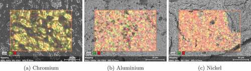
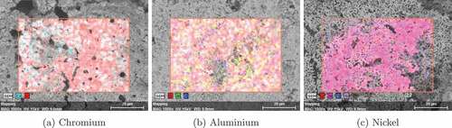
The spheres were immersed in ammonia solution (Merck KGaA, 25%) for 15 min to complete gelation and to remove the by-products, such as ammonium nitrate and formaldehyde.Citation30 The spheres were then air dried overnight at an ambient temperature and stored or washed again in petroleum ether if persistent silicon oil remained. The average shape and the diameter of the spheres were examined by a scanning electron microscopy (SEM) Hitachi TM 3000 microscope. The carbon and metal distributions, both on the surface and in the bulk of the air-dried spheres, were examined with energy dispersive X-ray spectroscopy (EDS) and Quantax 70 software. The metal distributions on the surface are shown in .
Fig. 4. SEM/EDS images showing the elemental distributions on the surfaces of the air-dried spheres of UN doped with (a) chromium, (b) aluminum, and (c) nickel, respectively.
IV.B. Nitridation by Carbothermal Reduction
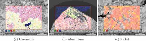
The air-dried spheres were placed in a molybdenum crucible. Carbothermal reduction was performed in a custom-made high-temperature graphite furnace (Thermal Technology LLC: Model 1000) in a mixture of nitrogen and hydrogen (95%N2+5%H2) with a gas flow of 1 L/min at 1500°C for 6 h. The nitrogen mixture was used during the heating step, and the reaction while cooling was performed in argon to prevent sesquinitride formation. The heating and cooling ramp was 20°C/min. After the thermal treatment, the microstructure and metal distribution were examined by SEM/EDS; see .
Fig. 5. SEM/EDS images showing the elemental distributions on the surfaces of the nitrided spheres of UN doped with (a) chromium, (b) aluminum, and (c) nickel, respectively.
IV.C. Pelletization of Nitrided Product
The nitrided spheres were either directly pressed into a form of green pellet or milled into fine powder and then pressed, as indicated in . The green pellet was sintered on a tungsten plate in argon with a flow of 1 L/min at 1800°C for 6 h. The mass and the dimensions of the final pellet were then measured in order to estimate density. The elemental distributions at the pellet surfaces were examined using SEM/EDS, and the resulting images are shown in .
Fig. 6. SEM/EDS images showing the elemental distributions on the surfaces of the sintered pellets of UN doped with (a) chromium, (b) aluminum, and (c) nickel, respectively.
IV.D. Dissolution in Boiling Water at Atmospheric Pressure
A pellet was put on a glass holder and hung roughly in the middle of a 0.5-L glass beaker containing 400 mL of deionized water. The water in the beaker was constantly stirred and heated to ensure a homogeneous temperature distribution. A watch glass was placed on top of the beaker to minimize the water vapor loss during boiling.
A pure UN pellet with a density of 75.6% of the theoretical density (TD), with the estimated composition UN0.78C0.22 based on Vegard’s rule, was used as the reference sample. This pellet collapsed and formed a suspension after 2 h of boiling.
V. RESULTS AND DISCUSSION
V.A. Neutronic Simulations
The initial neutronic simulations on nondoped UN and UO2 lattices showed that by using UN in a fuel pin lattice optimized for the use of UO2, the achievable cycle length could be increased by approximately 25%. However, by changing the fuel pellet diameter and the fuel pin pitch, the achievable cycle length could be increased by almost 45%.
The addition of a dopant to the lattice only marginally affected the achievable cycle length as calculated from the simulated multiplication factor. The effect was smallest when aluminum was used as the dopant, followed by chromium, nickel, and finally, niobium. These results motivated the following experimental investigation of manufacture and dissolution of UN doped with aluminum, chromium, and nickel.
V.B. Manufacture and Dissolution Experiments
The manufacture trials resulted in sintered pellets of UN doped with chromium, aluminum, and nickel, with densities around half the TD of UN (14.3 g/cm3). These densities are far below the approximately 95% targeted when UN is proposed for use as light water reactor fuel. The highest density was achieved when the nitrided spheres were ground to a fine powder before pressing, so this method is proposed for future manufacture trials. Slower-temperature ramps, longer holding times, and possibly the use of sintering aids could also be possible means for reaching desired densities, or alternatively, the use of spark plasma sintering.Citation31 Absolute densities are given in . Theoretical and relative densities cannot be stated since the actual composition of the produced pellets was not well characterized.
TABLE IV Densities of the Doped UN Pellets
During sintering, chromium partially disappeared from the outer surface of the pellet, as seen when comparing and . This effect would be emphasized in case longer sintering times were to be deployed, whereas spark plasma sintering might help mitigate the problem. Some surface contamination with tungsten can also be seen in , resulting from reaction between the pellet and the tungsten plate.
As shown in , aluminum segregated from the UN matrix during sintering and formed a separate lump of the side of the pellet, making it unsuitable as a dopant in this context. A segregation of aluminum from alloys with uranium has previously been reported.Citation32
The nickel was homogeneously distributed in the UN matrix until in the sintering step it segregated to the grain boundaries.
Dissolution tests were performed on UN pellets doped with chromium and nickel, respectively. The nickel-doped pellet collapsed after 10 min of boiling and formed a suspension. This might be due to the nickel located at the grain boundaries quickly turning into nickel oxide, thereby growing and tearing the pellet apart.
The chromium-doped pellet withstood 5 h of boiling without collapsing. This is especially remarkable since the chromium-doped pellet had the lowest density and would hence be assumed to have the highest open porosity.
Before and after the dissolution test, EDS analysis of the Cr-doped pellet surface showed a small presence of Cr. EDX patterns were collected to analyze which compounds were present at the pellet surface. Before the dissolution test, the only compounds found were uranium carbide nitride and W compounds resulting from the mentioned W contamination; see . No peaks were found corresponding to any Cr compounds. Since small amounts of Cr were observed in the EDS analysis, the Cr must be assumed to be incorporated in the uranium carbide nitride lattice, resulting in a small change in the lattice parameter and a corresponding shift of the peaks. Calculations of the lattice parameter of the uranium carbide nitride as a function of Cr content, however, showed that the Cr content at the pellet surface must be lower than 1%.
Fig. 7. XRD pattern indicating the presence of different compounds at the surface of the chromium-doped UN pellet (a) before and (b) after the dissolution test.
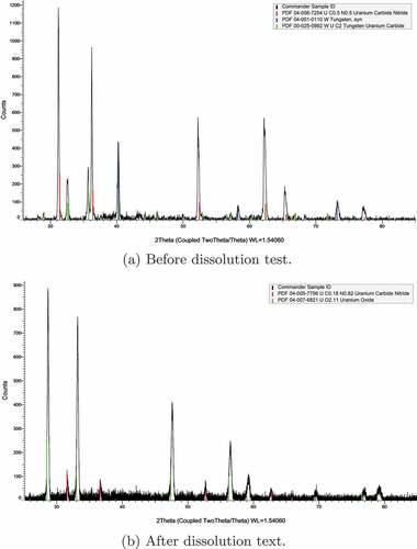
The EDX patterns collected after the dissolution test did not show any peaks corresponding to Cr compounds either; see . The W contamination did not appear, either because of the W having been washed off the surface or because a noncontaminated part of the surface was studied. Instead, very prominent peaks corresponding to UO2 were observed, although they were slightly shifted. No peaks corresponding to other uranium oxides (UO3, U3O8) were found. The lattice parameter indicated by the position of the peaks was determined to be 5.399 0.008 Å (2σ). The lattice parameter of (U0.9Cr0.1)O2 = 5.394 Å, assuming that Vegards law applies and a lattice constant for CrO2 of 4.71 Å. This indicates that a protective uranium oxide layer was formed on the surface during boiling, as suggested in Sec. I. The fact that the Cr-doped UN pellet withstood a longer period of boiling than the reference UN pellet suggests that the presence of Cr doping in this oxide layer improves its ability to protect the UN, possibly by preventing oxygen from diffusing through the oxide layer.
VI. SUMMARY AND CONCLUSIONS
Since UN is easily oxidized and soluble in water, the addition of dopants was proposed for stabilization. Based on literature studies, four possible candidates were proposed: aluminum, chromium, nickel, and niobium. Neutronic simulations were performed and concluded that with modified lattice dimensions for the UN lattice, none of the proposed dopants reduced the achievable cycle length below that of UO2 fuel. Aluminum had the smallest effect on the achievable cycle length, followed by chromium, nickel, and finally, niobium.
Manufacture trials were performed with UN doped with aluminum, chromium, and nickel using a modified internal gelation manufacture route. Aluminum was ruled out at this stage since the aluminum segregated during sintering. Dissolution tests were performed on UN pellets doped with chromium and nickel, during which the nickel-doped pellet collapsed after only a few minutes of boiling, whereas the chromium-doped pellet sustained a significantly longer period of boiling than the reference nondoped UN material. Based on these results, we propose that further research be performed on chromium as a dopant for stabilization of UN.
More detailed neutronic simulations should be performed involving complete fuel and reactor geometries (as opposed to the simplified pin cell simulations performed in this work). Further manufacture trials should be performed where in particular the pressing and sintering stages should be optimized in order to achieve significantly higher density (ideally about 95% of TD) of the sintered product. Finally, dissolution tests should be performed with pure and chromium-doped UN pellets of similar density, and preferably also with a range of different fractions of chromium, in order to find the smallest chromium fraction still yielding the desired stabilizing effect. Also, other tests of the stability of chromium-doped UN should be performed, such as exposure to hot steam.
Acknowledgments
The experimental work was financed by the Swedish Center for Nuclear Technology (SKC) through the MåBIL project. The neutronic simulations were supported by the Selma Andersson Foundation. This work was supported by the Selma Andersson Foundation [HT17]; Swedish Center for Nuclear Technology [MABIL].
Related Research Data
References
- S. B. ROSS and M. S. EL-GENK, “Thermal Conductivity Correlation for Uranium Nitride Fuel Between 10 and 1923 K,” J. Nucl. Mater., 151, 318 (1988); https://doi.org/10.1016/0022-3115(88)90026-8.
- J. A. WEBB and I. CHARIT, “Analytical Determination of Thermal Conductivity of W-UO2 and W-UN CERMET Nuclear Fuels,” J. Nucl. Mater., 427, 1–3, 87 (2012); https://doi.org/10.1016/j.jnucmat.2012.04.020.
- Y. ARAI et al., “Chemical Forms of Solid Fission Products in the Irradiated Uranium-Plutonium Mixed Nitride Fuel,” J. Nucl. Mater., 210, 161 (1994); https://doi.org/10.1016/0022-3115(94)90233-X.
- G. J. YOUINOU and R. S. SEN, “Impact of Accident-Tolerant Fuels and Claddings on the Overall Fuel Cycle: A Preliminary Systems Analysis,” Nucl. Technol., 188, 2, 123 (2014); https://doi.org/10.13182/NT14-22.
- R. M. DELL, V. J. WHEELER, and N. J. BRIDGER, “Hydrolysis of Uranium Mononitride,” Trans. Faraday Soc., 63, 1286 (1967); https://doi.org/10.1039/tf9676301286.
- S. SUGIHARA and S. IMOTO, “Hydrolysis of Uranium Nitrides,” J. Nucl. Sci. Technol., 6, 5, 237 (1969); https://doi.org/10.1080/18811248.1969.9732878.
- L. M. FERRIS, “Reactions of Uranium Mononitride, Thorium Monocarbide and Uranium Moonocarbide with Nitric Acid and Other Aqueous Reagents,” J. Inorg. Nucl. Chem., 30, 2661 (1968); https://doi.org/10.1016/0022-1902(68)80393-8.
- G. A. RAMA RAO et al., “Oxidation and Hydrolysis Kinetic Studies on UN,” J. Nucl. Mater., 185, 231 (1991); https://doi.org/10.1016/0022-3115(91)90340-D.
- A. HERMAN and C. EKBERG, “A Uranium Nitride Doped with Chromium, Nickel or Aluminum as an Accident Tolerant Fuel,” Res. Rev. J. Mater. Sci., 5, 4, 83 (2017); https://doi.org/10.4172/2321-6212.1000196.
- B. BEVERSKOG and I. PUIGDOMENECH, “Revised Pourbaix Diagrams for Chromium at 25-300°C,” Corros. Sci., 39, 1, 43 (1997); https://doi.org/10.1016/S0010-938X(97)89244-X.
- D. A. JONES, Principles and Prevention of Corrosion, Chapter 4. Passivity, Prentice-Hall, Inc. (1996).
- P. AALTONEN and H. HANNINEN, “Water Chemistry and Behaviour of Materials in PWRs and BWRs,” in “Report of an Advisory Group Meeting on Design Approaches for Heating Reactors,” p. 205, International Atomic Energy Agency (1997).
- “Power Plant Chemistry Measurement Advancements: Oxidation Reduction Potential,” Honeywell; https://www.honeywellprocess.com/library/marketing/notes/power-plant-chemistry-measurement-advancements-orp.pdf ( current as of 2013).
- N. TAKENO, “Atlas of Eh-pH Diagrams, Intercomparison of Thermodynamic Databases,” p. 419, National Institute of Advanced Industrial Science and Technology Research Center for Deep Geological Environments (2005).
- “Neutron Cross Section of the Elements”; http://periodictable.com/Properties/A/NeutronCrossSection.html ( current as of Dec. 2018).
- N. R. BROWN et al., “Neutronic Performance of Uranium Nitride Composite Fuels in a PWR,” Nucl. Eng. Des., 275, 393 (2014); https://doi.org/10.1016/j.nucengdes.2014.04.040.
- K. D. JOHNSON et al., “Fabrication and Microstructural Analysis of UN-U3Si2 Composites for Accident Tolerant Fuel Applications,” J. Nucl. Mater., 477, 18 (2016); https://doi.org/10.1016/j.jnucmat.2016.05.004.
- J. LEPPÄNEN, “Serpent—A Continuous-Energy Monte Carlo Reactor Physics Burnup Calculation Code,” VTT Technical Research Centre of Finland (2012).
- J. ZAKOVA and J. WALLENIUS, “Fuel Residence Time in BWRs with Nitride Fuels,” Ann. Nucl. Energy, 47, 182 (2012); https://doi.org/10.1016/j.anucene.2012.03.033.
- J. FINK, “Thermophysical Properties of Uranium Dioxide,” J. Nucl. Mater., 279, 1, 1 (2000); https://doi.org/10.1016/S0022-3115(99)00273-1.
- G. LEINDERS et al., “Accurate Lattice Parameter Measurements of Stoichiometric Uranium Dioxide,” J. Nucl. Mater., 459, 135 (2015); https://doi.org/10.1016/j.jnucmat.2015.01.029.
- S. HAYES, J. THOMAS, and K. PEDDICORD, “Material Property Correlations for Uranium Mononitride: I. Physical Properties,” J. Nucl. Mater., 171, 2, 262 (1990); https://doi.org/10.1016/0022-3115(90)90374-V.
- S. HAYES, J. THOMAS, and K. PEDDICORD, “Material Property Correlations for Uranium Mononitride: IV. Thermodynamic Properties,” J. Nucl. Mater., 171, 2, 300 (1990); https://doi.org/10.1016/0022-3115(90)90377-Y.
- S. HAYES, J. THOMAS, and K. PEDDICORD, “Material Property Correlations for Uranium Mononitride: III. Transport Properties,” J. Nucl. Mater., 171, 2, 289 (1990); https://doi.org/10.1016/0022-3115(90)90376-X.
- N. R. BROWN, M. TODOSOW, and A. CUADRA, “Screening of Advanced Cladding Materials and UN-U3Si5 Fuel,” J. Nucl. Mater., 462, 26 (2015); https://doi.org/10.1016/j.jnucmat.2015.03.016.
- M. J. DRISCROLL, T. J. DOWNAR, and E. E. PILAT, The Linear Reactivity Model for Nuclear Fuel Management, Americal Nuclear Society, La Grange Park, Illinois (1990).
- K. INSULANDER BJÖRK, V. FHAGER, and C. DEMAZIÈRE, “Comparison of Thorium-Based Fuels with Different Fissile Components in Existing Boiling Water Reactors,” Prog. Nucl. Energy, 53, 6, 618 (2011); https://doi.org/10.1016/j.pnucene.2010.03.004.
- A. SAJDOVA, “Accident-Tolerant Uranium Nitride,” p. 76, Chalmers University of Technology (2017).
- K.-C. JEONG et al., “UO3 Intermediate Particle Preparation Using the Sol-Gel Process,” Trans. Korean Nucl. Soc. (2005); https://www.kns.org/files/pre_paper/17/231%EC%A0%95%EA%B2%BD%EC%B1%84.pdf ( current as of Feb. 2019).
- K. IDEMITSU et al., “Manufacturing of Zirconia Microspheres Doped with Erbia, Yttria and Ceria by Internal Gelation Process as a Part of a Cermet Fuel,” J. Nucl. Mater., 319, 31 (2003); https://doi.org/10.1016/S0022-3115(03)00130-2.
- P. A. LESSING, “Oxidation Protection of Uranium Nitride Fuel Using Liquid Phase Sintering,” INL/EXT2012;12-24974, Idaho National Laboratory (2012); https://doi.org/.
- W. THURBER and R. BEAVER, “Segregation in Uranium-Aluminum Alloys and Its Effect on the Fuel Loading of Aluminum-Base Fuel Elements,” Oak Ridge National Laboratory (1958).
