
Abstract
ELI Beamlines is a newly constructed petawatt (PW) laser-based accelerator facility. Its flagship laser has a nominal peak power of 10 PW with a pulse duration of 150 fs. The radiation fields emerging from the laser-target interactions will be pulsed and made of mixed particles of high intensity and energy, thus posing new and daunting challenges compared to conventional radiation protection. The civil engineering constraints of a laser facility bring localized weaknesses to the shielding structures. The ultrashort pulses in conjunction with ultrahigh dose rates strain the capabilities of the commercially available radiation detectors. The complexity of modeling laser-target interactions and the resulting ionizing radiation complicates the radiation protection calculations. This paper is a review of the radiation protection challenges at ELI Beamlines, the adopted solutions, and the practices to minimize the harmful effects of ionizing radiation linked to its activities. Some of the presented solutions may have universal validity, while others are specific to this site and can only serve as an inspiration.
I. INTRODUCTION
In 1998, Backus et al.Citation1 published the first review of ultrahigh-power lasers, which identified only one petawatt (PW)-class laser in operation worldwide. Less than 3 decades later, PW lasers are numerous, and projects for future laser facilities are regularly being proposed.Citation2,Citation3 Both research and industry, in fact, are pushing toward the development of evermore powerful lasers with higher repetition rates and higher intensities. These remarkable facilities enable pioneering research and technological advances in a variety of fields, including but not limited to, plasma and fusion research, atomic molecular and optical physics, femtosecond chemistry, astrophysics, high-energy physics, materials science, biology, and medicine.Citation4
In fact, ultrahigh-power lasers are exploited to produce and accelerate particles, thus constituting a novel family of accelerators. Alongside the rapid improvements in laser-plasma acceleration technology, there is a rapid increase in the correlated radiological risks. In fact, the expected high energies (up to tens of gigaelectron-volts for electrons and on the order of 1 GeV for proton beams) and current repetition rates (the estimated number of particles per laser shot can be 109 to 1010 and 1010 to 1012 for electron and proton beams, respectively) require accurate radiation protection (RP) studies to protect personnel, the general public, the environment, and equipment, all the time assuring efficient and smooth operations.Citation4–8
This paper provides a comprehensive overview of the RP hazards at the Extreme Light Infrastructure (ELI) Beamlines laser-driven accelerator facility. Attention is given to the adopted RP measures, procedures, equipment, and tools used to mitigate these hazards.
II. ELI EUROPEAN RESEARCH INFRASTRUCTURE CONSORTIUM
The design and construction of the ELI facilities started in the early 2000s, but it was only in 2021 that the European Commission established the ELI projectCitation4 as a European Research Infrastructure ConsortiumCitation9 (ERIC), thus creating the ELI ERIC. The ELI ERIC is the largest international civilian laser-based user facility network. The establishment of the ELI ERIC enables researchers and industries to access the world’s largest collection of high-power and ultrafast lasers. As an international organization, its member countries contribute scientifically and financially to the consortium. The founding members are the Czech Republic, Hungary, Italy, and Lithuania, while Germany and Bulgaria are founding observers with the aim to fully join at a later date. Other European countries have expressed interest in joining as well.
The ELI ERIC facilities are located in Hungary, Romania, and the Czech Republic. The Hungarian laser facility, ELI Attosecond Light Pulse Sources, uses pulses of attosecond length for material sciences and biology research.Citation10 ELI Nuclear Physics in Romania focuses on photonuclear physics, bringing together high-power lasers and nuclear physics.Citation11 Located in the Czech Republic, ELI BeamlinesCitation12 aims to investigate high-field high-density physics, developing high-brightness sources of X-rays, as well as proton, electron, and ion beams.
III. ELI BEAMLINES
ELI BeamlinesCitation12 is a laser-driven user facility located south of the city of Prague, Czech Republic. Its research activities can be classified in complementary areas of scientific interest: development and testing of novel technologies for multi-PW laser systems, plasma physics, high-field physics experiments, production of femtosecond secondary sources of ionizing radiation (extreme ultraviolet radiation, X rays, gammas, electrons, and protons) to be used in interdisciplinary applications in physics, biology, medicine, and material sciences.Citation13 In-house experiments started as early as the first half of 2018. The first user calls were issued in 2019, and the first user experiments were successfully performed later that same year. Licenses to operate the stations producing ionizing radiation were secured from the Czech State Office for Nuclear Safety (see Sec. IV).
ELI Beamlines houses four main laser systems (see Sec. III.A) that serve a dozen experimental stations (see Sec. III.B) with the possibility of adding more in the future. The laser systems and the experimental stations are located in a dedicated building along with the necessary auxiliary systems, such as cooling, ventilation, and vacuum systems (see Sec. VII).
III.A. Laser Systems
The current and nominal parameters of the four main laser systems are listed in . L1-Allegra, simply meaning cheerful in Italian, was developed in-house by the ELI Beamlines laser team and has been in operation since 2018 (CitationRef. 14). It is designed to generate <20-fs pulses with energies exceeding 100 mJ per pulse at a 1-kHz repetition rate. The L2-DUHA laser (Dual-beam Ultra-fast High-energy OPCPA Amplifier, “duha” meaning rainbow in Czech) was designed inhouse to provide 100-TW-level pulses at a 50-Hz repetition rate and an 820-nm wavelength.Citation15 The L2-DUHA is currently being installed, with the start of the commissioning in 2023. The L3-HAPLS (High-Repetition-Rate Advanced Petawatt Laser System) is designed to deliver PW pulses with a peak energy of 30 J and <30-fs pulse lengths at a repetition rate of 10 Hz (CitationRef. 16). This system was developed at the Lawrence Livermore National Laboratory in cooperation with ELI Beamlines. The L3-HAPLS has been in operation since 2019. Finally, the L4-Aton, named after the Egyptian sun god, is in trial operation. It will eventually deliver three different laser beams. The target peak energy of the most powerful one is an impressive 10 PW with a pulse duration of 150 fs (CitationRef. 17).
TABLE I Present and Target Parameters of the Laser Systems at ELI Beamlines
III.B. Experimental Stations
Among all the experimental stations at ELI Beamlines, at least nine are expected to generate ionizing radiation. These are summarized in . Photon, electron, proton, and ion beams will be produced and accelerated. Neutrons will be produced as well, but only as secondary byproducts.
TABLE II Experimental Station at ELI Beamlines Expected to Produce Ionizing Radiation
The High-order Harmonic GenerationCitation18 (HHG) experiment is dedicated to the production of ultrashort pulses of tunable coherent extreme ultraviolet soft X-ray radiation using the L1-Allegra. The Plasma X-ray SourceCitation19 (PXS) experiment produces high-brightness X-ray beams with energies varying from 3 to about 77 keV using the L1-Allegra. The E2 X-ray Source, instead, is dedicated to the generation of ultrafast and bright hard X-rays using a PW-class laser with a 10-Hz repetition rate.Citation20 It relies on the L3-HAPLS laser focused on gas targets. The Laser Undulator Incoherent Source (LUIS) experimental station aims to produce laser-driven electron beams for the generation of initially spontaneous, and subsequently coherent, photon radiation.Citation21 The electron beams will have maximum energies of 600 MeV with a peak energy spread of less than 1%. The Electron Beam Accelerator (ELBA) for fundamental science and applications will accelerate electrons up to energies of tens of gigaelectron-volts.Citation22 Both the LUIS and ELBA use the L3-HAPLS and in the future will also use the L2-DUHA and L4-Aton lasers.
The Allegra Laser For Acceleration (ALFA) experimental station, instead, uses the L1-ALLEGRA laser to generate a 50-MeV electron beam.Citation23 The Testbed for high Repetition-rate Sources of Accelerated particles (TERESA) is designed for proton and electron accelerationCitation24 using the L3-HAPLS laser. Its goal is to provide proton beams of 10 to 15 MeV and electron beams of 100 to 150 MeV. The ELI Multidisciplinary Applications of laser-Ion Acceleration (ELIMAIA), instead, aims at ion acceleration using the L3-HAPLS and L4-ATON lasers; in its first phase it will accelerate protons up to 60 MeV and later up to 250 MeV (CitationRef. 25). Finally, the Plasma Physics Platform (P3) is a multifunctional experimental infrastructure. With its 50-m3 vacuum chamber, it pursues an ambitious experimental program in high-field laser-plasma interaction as well as high-energy density physics.Citation26 P3 is served by the L3-HAPLS and L4-Aton laser systems and is designed to simultaneously focus up to five different laser beams.
IV. LEGAL REQUIREMENTS AND INTERNAL RP CRITERIA
In the Czech Republic, the State Office for Nuclear Safety (SÚJB, Státní Úřad pro Jadernou Bezpečnost) is responsible for countrywide monitoring, assessment, and control in the fields of personal and environmental protection against the adverse effects of ionizing radiation. Its work is regulated by the Atomic Act 263/2016. on the Peaceful Use of Nuclear Energy and Ionizing Radiation and 20 additional decrees, which comprise the Nuclear Law.Citation27 One of the most relevant documents to ELI Beamlines is Decree 422/2016 Coll. on the RP and security of a radioactive source. The Nuclear Law complies with the relevant recommendations and legislation from the International Commission on Radiological Protection, European Atomic Energy Community, International Atomic Energy Agency, and the European Union.Citation28,Citation29
The RP group at ELI Beamlines works in close collaboration with SÚJB, which carries out regular inspections and audits and grants the commissioning and operational licenses for each experimental station. The details of the implementation of individual commissioning phases and any nonroutine activities are covered by internally issued temporary work authorizations, which include a justification of the activity to be carried out, a full risk analysis, and the implemented safety measures. The laser building (see Sec. VII), which houses the laser systems and the experimental stations, is divided into supervised and controlled areas. The delineation of the areas follows the law guidelines. Supervised areas are established wherever the effective dose could exceed 1 mSv/year or the equivalent dose to eye lens, skin, or extremities could exceed 1/10 of the legal limits (see second column in ). Instead, controlled areas are delineated where the effective dose could exceed 6 mSv/year or the equivalent dose could exceed 3/10 of the limits for skin or extremities or 15 mSv for eye lens (see second column in ).
The second column of lists the maximum allowed legal exposure limits for radiation workers in the Czech Republic. However, in agreement with the national authorities and always following the “as low as reasonably achievable” (ALARA) principle,Citation30 ELI Beamlines aims at the more stringent internal RP criteria listed in the third column of . This optimization of protection and safety is achieved by a careful construction of the experimental halls and control rooms, an attentive choice of shielding materials (see Sec. VII), and detailed work plans for each experiment where worst-case scenarios are considered. During upgrades, commissioning, and even unscheduled interventions, risk assessments are used to minimize the duration of work in radiation areas, allow for adequate cooldown time depending on the urgency of the intervention, and optimize the use of necessary human resources.
TABLE III Maximum Legal Exposure Limits for Radiation Workers in the Czech RepublicCitation27 and ELI Beamlines Internal Limits*
Any exposure of radiation to workers (even if well within legal limits) has to be justified in relation to the urgency and difficulty of the work and the specific expertise of the personnel involved. Additionally, for pregnant or breastfeeding radiation workers, it is forbidden to perform tasks involving possible contamination risks (the legal limit in the Czech Republic for pregnant radiation workers is 1 mSv from when they notify their employer until the end of their pregnancy). Finally, the total maximum effective dose to nonradiation workers and the general population is less than 0.1 mSv/year (the legal limit in the Czech Republic is 1 mSv/year for all sources of artificial radiation not connected to medical procedures).
The head of the RP group is the appointed Radiation Safety Officer, responsible for the safe use of radiation and radioactive materials as well as regulatory compliance. An internal Radiation Committee has been established to advise facility management on radioprotection matters, recommend policies, review accident investigations, and evaluate potential protective measures. The members, appointed by the institute director, are the main RP stakeholders, such as representatives of the experimental teams and the RP group.
V. RP CHALLENGES AT ELI BEAMLINES
When designing and implementing the RP and safety measures at ELI Beamlines, existing international recommendations and recognized best practices were followed. However, high-power and high-intensity laser facilities are new and distinctive radiation installations, for which recognized standards are currently being drafted. Therefore, it was necessary to develop ad hoc solutions for the unique RP challenges faced at ELI Beamlines. An overview of these challenges and the adopted solutions are presented.
V.A. Wall, Floor, and Ceiling Penetrations
When designing the civil structure of the facility, RP concerns were carefully considered and attention was paid to shielding requirements. Nevertheless, hundreds of penetrations are present in the ceilings and walls. While these are needed to transport the laser beams and auxiliary systems throughout the building, at the same time they introduce significant weaknesses in the shielding structures. Further, most of the penetrations are wide, typically measuring 1 × 1 m, with the largest ones reaching 9 m2. These apertures are effectively empty since they accommodate vacuum tubes, typically dedicated to laser beam transport. Consequently, many are at laser beam height (1.3 m from the floor), where the highest dose rates are expected. Besides, these penetrations must be built straight, since each turn of the laser is not only costly, but it significantly deteriorates the properties of the laser beam.
Further penetrations are used for the cooling system, transport of gases needed in the experiments, and for the many air-conditioning units needed to comply with the EN ISO 14644 standard for clean roomsCitation31 (see Sec. V.A). Also, narrow but nonnegligible channels run beneath the experimental floors for cable passageways. All these wall and floor weaknesses offer paths for the radiation to leak from one area to another. Each penetration was studied separately considering hazards related to ionizing radiation, electromagnetic pulses (EMPs), and fire. Different solutions were adopted depending on the dimensions and positions of the penetrations and on the equipment within. Concrete blocks have been placed in the cavities and local shielding has been designed wherever possible. Polyethylene and borated polyethylene for neutron shielding have been used to fill some of the ceiling penetrations (loose material with a density of 430 g/l that can be tightly packed in the gaps). Finally, some penetrations, such as the ventilation ducts, cannot be closed off nor shielded. Active monitoring detectors have been placed in strategic locations close to these penetrations, where the dose rate is expected to be higher and/or where personnel may be present.
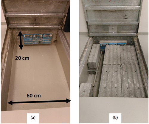
shows the simulated ambient dose equivalent [H*(10)] rates in and around the LUIS experimental hall. Simulations were performed using the FLUKA Monte Carlo codeCitation32,Citation33 (see Sec. VI). A long channel for signal and power cables runs under the floor along the direction of the beamline into the control room. The channel is 60 cm wide and 20 cm deep (). Radiation may leak through the channel into the control room. The increase in the dose rate in the control rooms was estimated to be on the order of 10 nSv/pulse. For this reason, a concrete shielding wall was designed. It measures 80 × 60 × 200 cm, and its location is shown in . The estimated reduction in H*(10) in the control room is of about two orders of magnitude. Finally, as an extra and redundant shielding measure, concrete blocks were placed inside the channel () in compliance with the ALARA principle (see Sec. IV).
Fig. 1. Monte Carlo estimation of the H*(10) rate in the LUIS experimental hall. An electron beam with a peak energy of 400 MeV with 100 pC per pulse was used as the source term for this study. No additional shielding is installed between LUIS and the control room. Radiation leaks through the floor penetrations toward the control room.
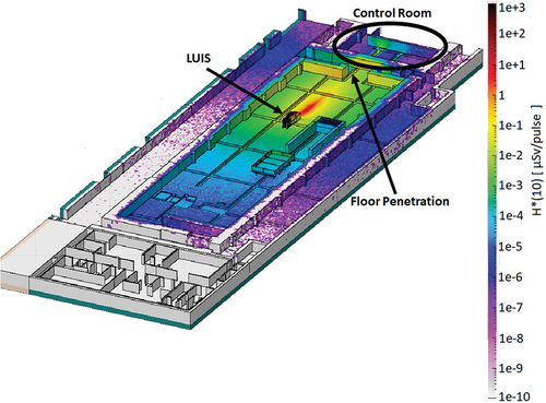
Fig. 2. Monte Carlo estimation of the H*(10) rate in the LUIS experimental hall. An electron beam with a peak energy of 400 MeV with 100 pC per pulse was used as the source term for this study. A concrete shielding wall is shown in the figure. The H*(10) rate reduction in the control room is of two orders of magnitude (compared with ).
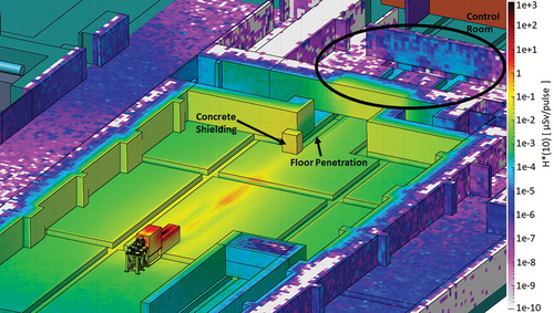
Fig. 3. Picture of the floor penetration in the LUIS experimental hall (a) without and (b) with concrete blocks. The same set is installed on the control room side of the penetrations, but inverted, thus forcing juggled routing of the cabling. These concrete blocks are a redundant shielding easily added in compliance with the ALARA principle (see Sec. IV).
V.B. Source Terms
The ionizing radiation generated in laser-target interactions has a few important characteristics. First, it is generated in very short pulses.Citation34 Second, it comprises several types of particles (e.g., photons, electrons, and neutrons) spanning over a very large energy range.Citation34 Since the beginning, RP assessments at ELI Beamlines have been based on Monte Carlo simulations. The descriptions of ionizing radiation used as inputs to the simulations (called source terms) were either extrapolated from previous experiments or estimated via particle-in-cell simulations,Citation35 which are used to model the interaction of lasers with targets. In fact, these interactions are themselves the subject of research.Citation36 Hence, they suffer from limited experimental reproducibility and their modeling faces mathematical and computational challenges.Citation37
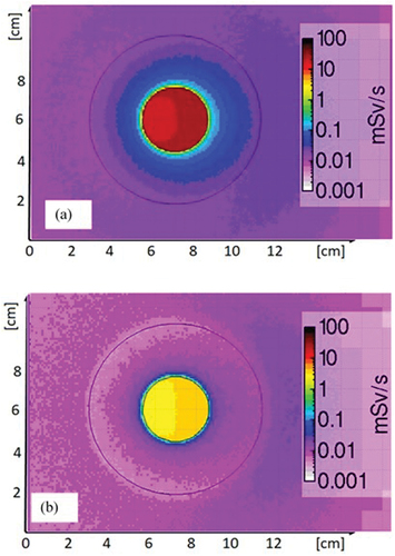
As a result, the source terms used for RP assessments suffer from intrinsic uncertainties much larger than those affecting source terms used in conventional accelerators. Therefore, a conservative worst-case scenario approach was used for the source energy, charge, repetition rate, and geometrical beam characteristics. and show how minimum changes to the source term can have a ripple effect on the predicted doses. The estimated H*(10) rate outside the exit window of the interaction chamber of ALFA is plotted considering an electron beam with 3.5-MeV average energy and 2.5-MeV full-width at half maximum, but with different beam divergences (12 and 100 mrad). The exact beam divergence is unknown and may vary significantly between data-taking runs. As seen in the plots, the variations in the expected radiation field are remarkable.
Fig. 4. Monte Carlo ambient dose equivalent rate outside the exit window of the ALFA interaction chamber assuming an electron beam with 3.5-MeV average energy and 2.5-MeV full-width at half maximum. The beam divergence was set to (a) 12 mrad and (b) 100 mrad.
V.C. Ultrashort Laser Pulses
Multi-TW and PW lasers with ultrashort pulse durations (tens or hundreds of femtoseconds) interacting with solid, liquid, and gaseous targets will produce high-intensity, high-energy, and pulsed radiation fields, which pose new challenges compared to conventional RP.
The interaction of subpicosecond laser pulses with solid targets generates strong EMPs that can cause damage to electronic devices.Citation38–40 This imposes severe constraints on the detectors that can be employed in a high-power laser facility. Until now, RP detectors have not been tested for resistance to EMPs, as these were never associated with the generation of ionizing radiation. Different mitigation strategies could be pursued.Citation38 The most relevant for RP purposes, is to shield active detectors within Faraday cages to try to protect them from the EMPs. Another approach is to use passive detectors, whenever possible, as these have never been shown to suffer from EMPs. Both approaches are used at ELI Beamlines. Additionally, all the experimental halls are built as standalone Faraday cages to protect both personnel and equipment, including RP detectors for area monitoring.
The ultrashort laser pulse duration implies that the ionizing radiation is also produced in very short pulses. Real-time radiation detection instruments available on the market are typically designed and optimized for continuous fields. The International Organization for Standards (ISO) defines a continuous radiation as ionizing radiation with a constant dose rate at a given position in space for a time interval longer than 10s (CitationRef. 41). The main challenge for dosimetric systems is to process high detector loads within short time periods (ultrahigh dose rates), maintain an appropriate dead-time behavior, ensure pile up suppression, and reliably distinguish signal from noise.Citation42 Many of the commercially available electronic dosimeters can detect gradual intensity changes, but do not provide reliable dose values in these pulsed fields.Citation43 Therefore, it is good practice to use passive systems in conjunction with active ones (see Sec. X for further details). Concurrently, the RP group at ELI Beamlines is participating in international efforts to develop new metrological tools needed for traceable absorbed dose measurementsCitation44,Citation45 and to test existing and newly developed detectors at ultrahigh pulse dose rate beam facilities.
V.D. Radiation Damage to Electronics
The potential danger posed by ionizing radiation to electronics was first postulated in 1962 (CitationRef. 46) and has moved center stage in large scientific laboratories with the CERN Neutrinos to Gran Sasso (CNGS) accident at CERN in 2007 (CitationRef. 47). Therefore, the risks of damage to electronics, both due to single-event effects (SEEs) and cumulative effectsCitation48 is regularly investigated at ELI Beamlines in order to identify situations that could potentially harm the regular operations and to implement mitigation actions. This risk is another argument in favor of using a combination of active and passive detectors for area and personal monitoring. These studies are important also for the experimental teams to understand, limit, and possibly avoid radiation-to-electronics damage.
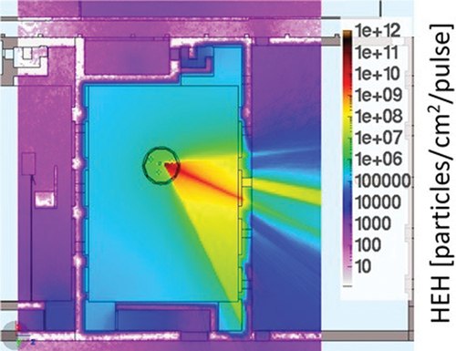
High-energy (>20 MeV) Hadron (HEH) fluence is used to characterize stochastic SEE failures. shows the estimate of the HEH fluence generated in a solid target experiment with the L4-ATON in the E3 hall. The values are given in the number of particles per square centimeter per laser shot. Values below 107 particles/cm2/year are considered acceptable for nonradiation-hard electronics.Citation49,Citation50 Therefore, the number of shots per year limits the possible placements of the radiation detectors, and vice versa, the need to monitor the radiation level in certain areas, while avoiding failures in the monitoring devices that may limit the run time.
Fig. 5. HEH fluence in the E3 experimental hall for a solid target experiment driven by the L4-ATON laser, estimated via FLUKA simulations.
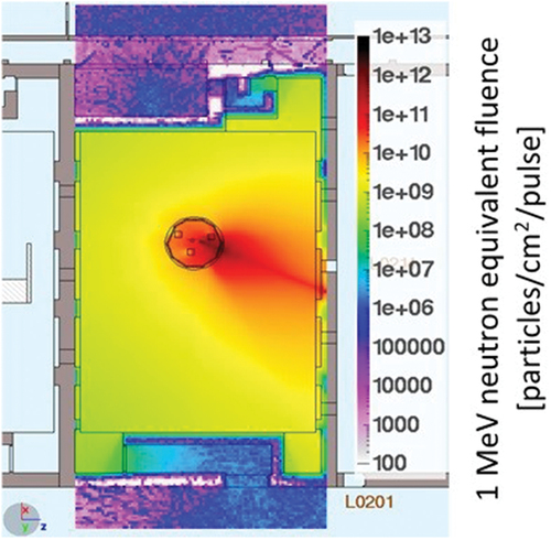
Total ionizing dose and 1-MeV-neutron equivalent fluence in silicon (Si-1 MeV neq), instead are used to address the cumulative effects. Assuming 36 000 laser shots of the L4-AATON in a year (2 h/day and 300 days/year at one shot per minute), the estimated Si-1 MeV neq fluence is shown in . Areas with values of 1010 particles/cm2/year are considered safe for commercial electronics.
Fig. 6. Si-1 MeV neq fluence in the E3 experimental hall for a solid target experiment driven by the L4-ATON laser, estimated via FLUKA simulations.
The need to develop a deeper understanding of the radiation damage to electronics has led the scientific community to launch the RADNEXT project.Citation51 The RP group at ELI Beamlines is an active participant in this H2020 INFRAIA-02-2020 infrastructure, which is aimed at building an international community of laboratories, universities, and industries working on the radiation-to-electronics-damage problem.
V.E. Clean Rooms
High-power lasers are transported in vacuum and need to be operated in clean room conditions in order to not deteriorate the laser quality and not damage any device. All experimental halls at ELI Beamlines are classified as ISO 5 or ISO 7 according to the ISO standard for clean rooms.Citation31 Consequently, shielding materials and any monitoring equipment must comply with the cleanliness requirements. They must have smooth surfaces for easy cleaning, they should be resistant to cleaning chemicals, and they should release neither dust nor particles into the air. Effectively, for the construction of shielding and beam dumps, this implies that concrete blocks can be used only if appropriately coated and/or covered. Granite, only slightly more expensive than concrete but with approximately the same shielding properties, is considered a suitable alternative. Adequate surface finishing allows for easy polishing while demonstrating acceptable chemical absorbency. Besides, it is widely available and can be machined to the needed shape and dimensions. For what concerns monitoring devices, all the passive area dosimeters are packaged in clean aluminum or plastic containers. The active detectors have been carefully selected based on manufacturing specifications and were thoroughly cleaned before installation.
The requirement for cleanliness is even more pronounced for objects inside the interaction chambers. Most materials are not compatible with the vacuum requirements, including most plastics, due to their outgassing. Thus, further constraints are imposed on the choice of materials, e.g.,, on the cartridges of passive detection systems.
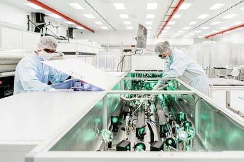
Finally, clean room attire and laser-safety goggles limit movement and visibility, extending the time needed for any intervention (see ). This limitation must be factored in when planning activities in radiation areas. On the other hand, the compulsory protective clothing (including gloves) reduces the risk of skin contamination when handling activated material.
Fig. 7. Operators at work on the laser system. Clean room ISO 7 attire and laser-safety goggles limit movement and visibility, increasing the time needed for each intervention, and consequently, the exposure time.
VI. MONTE CARLO SIMULATIONS
ELI Beamlines is a new facility still in the commissioning phase. At the time of writing, only two of the main laser beamlines were fully operational and were still being expanded and upgraded to reach their nominal performance, while experimental stations were in various phases of commissioning. Therefore, RP assessments have been mostly driven by Monte Carlo simulations. The RP group at ELI Beamlines uses mainly FLUKA (CitationRefs. 32 and Citation33). FLUKA is a general-purpose Monte Carlo code for the interaction and transport of hadrons, heavy ions, and electromagnetic particles from a few kilo-electron-volts to cosmic-ray energies in arbitrary materials. The code is used worldwide for RP calculations at accelerator facilities. In fact, it is one of the few codes that provides combined prompt and residual dose rate calculations as well as the simulation of particle interactions in the energy range needed. FLUKA is able to transport 60 different elementary particles and any heavy ions.Citation52 Also, it includes a solver routine for the Bateman equations,Citation32,Citation33 estimators relevant for radiation damage to the electronics, and a user-friendly graphical interface FLAIR (CitationRef. 53).
A single, highly modular, and highly scalable FLUKA simulation input file is used for all RP studies at ELI Beamlines. In more than 50 000 lines of code, all experimental halls and stations have been modeled and relevant physics settings activated. This ensures a single and uniform environment across all performed RP studies where a sufficiently detailed and realistic simulation model of the laser building is used. The FLUKA geometry model of the experimental halls located in the basement of the laser building is shown in .
Fig. 8. FLUKA geometry model of the experimental halls at ELI Beamlines. This corresponds to the basement in .
Several tasks are performed by means of Monte Carlo simulations. One of the most relevant is the characterization of radiation field maps based on source terms agreed upon with the experimental teams and relying on either extrapolation from previous experiments with similar conditions or particle-in-cell simulations. Radiation field maps are generated for several quantities, like H*(10), HEH fluence, and Si-1 MeV neq fluence, and are then used for the assessment of the risk for humans and machines. The identification and the design of possible mitigation options are also based on Monte Carlo simulations. This includes identifying more suitable locations for devices and the design of radiation shielding. Additionally, FLUKA simulations are used to estimate the possible induced radioactivity of materials exposed to the radiation generated in laser-target interactions and advanced planning for the management of the activated materials. In fact, FLUKA offers unique capabilities for activation studies as the prompt and residual radiation particle cascades are simulated in parallel and are based on microscopic models for nuclide production and analytical solutions of the Bateman equations for activity buildup and radioactive decay.Citation32,Citation33
VII. EXPERIMENTAL HALLS: STRUCTURE AND SHIELDING OF THE PROMPT RADIATION
To fulfill the aforementioned RP criteria as well as scientific and technological needs, civil engineering constraints, and national and international regulations, many Monte Carlo simulations and analytical calculations have been performed.Citation32,Citation33,Citation54 The results of these calculations drove the design and the construction of the laser building. All calculations were performed under conservative assumptions, thus ensuring comfortable safety factors. Maximal energy and intensity values were used for all source terms to obtain a conservative estimate of the radiological hazards. Laser operations were assumed to cover up to 250 days/year and 8 h/days, if not specified differently by the experimental teams. The soil surrounding the basement provides extra shielding but was not taken into account during the design of the facility. Finally, all penetrations (see Sec. VI) were considered empty, i.e., without shielding material.
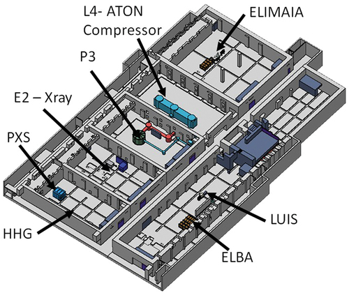
shows a schematic view of the laser building. The building is made of reinforced ordinary concrete. During construction, special attention was paid to the concrete density (at least 2430 kg/m3 for fresh concrete, corresponding to 2320 kg/m3 for mature concrete) and to the homogeneity (uniform compaction) of the built walls. Poured concrete was used, except for the areas requiring heavier shielding, where high-density (4000 kg/m3) concrete was used. In this case, to prevent the settling of the aggregates and thus compromise the shielding properties, prefabricated blocks of material were used.
Fig. 9. Diagram of the Laser building, indicating the locations of the main technological units.
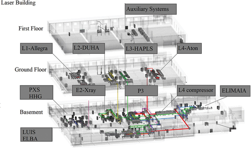
The ground floor houses the main laser systems and the experimental stations ALFA and TERESA, and it is classified as a supervised area (see Sec. IV). Instead, all the other experimental stations are in the basement, which is 7.6 m underground and is classified as a controlled area (see Sec. IV). The external and internal walls separating the six main experimental halls are typically 1.60 m thick. The minimal concrete thickness between the floors is 0.5 m. These thicknesses allow for access to any experimental hall regardless of the operational state of the adjacent ones.
Each experimental hall has a dedicated control room. From the control room, access to the hall is through a maze cut by three doors: an EMP door, a neutron shielding door, and a fire safety door. The neutron shielding doors are made from 5 cm of high-density pressed laminated wood with a hydrogen content of 6%, high content of low-Z elements (carbon 50%, oxygen 43%), and a mass density of ~1000 kg/m3, suitable for neutron shielding.Citation55,Citation56 Each hall is also equipped with large doors allowing for the transport of bulky material. Also, this access is protected by a concrete maze and closed by large EMP shielding doors. These large EMP doors and the ones separating the control rooms from the experimental halls are all connected to the interlock system (see Sec. IX). Where relevant, dismountable shielding walls and beam dumps are used to avoid the activation of walls and floor. Standard-density (2350 kg/m3) concrete blocks and granite are used for this purpose.
The effectiveness of the proposed measures was thoroughly investigated. shows an example of such a study for a hall with a 500-MeV electron source. In the experimental hall, the prompt H*(10) rate is higher than 25 µSv/day (assuming 1800 shots per day). The rate drops to 2.5 to 4.0 µSv/day in the plant room, where the support facility systems (air-conditioning and cooling units, roughing vacuum pumps, etc.) are located. The experimental hall and the most dangerous sections of the plant room are interlocked during run time and access is forbidden (see Sec. IX). The adjacent corridor has an estimated H*(10) rate of less than 1 µSv/day.
Fig. 10. H*(10) rate simulated in an experimental hall hosting a 500-MeV electron source and 1800 shots per day (vertical view). The corridor and control room are treated as a normal workplace, i.e., personnel will be present for daily 8-h shifts.Citation54
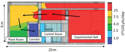
These studies were done simulating the entire electromagnetic cascade with all secondary particles, including low-energy neutron interactions (<20 MeV). Photons and electrons were transported down to energies of 1 keV (kinetic energy). The electrons, photons, and neutrons are the main contributors to the dose rate. The shielding wall between the hall and the control room is thick enough to absorb the electromagnetic components and the neutrons impacting directly upon it. The electromagnetic component is, therefore, well contained in the experimental hall (which is empty during operations). Instead, through multiple scatterings, the neutron prompt radiation “leaks” through the ventilation ducts above the control room toward the plant room, which is a low-occupancy area (see arrows in ). The corridor walls have been designed such that the H*(10) rates in the control room are comparable with the background rate, as desired and as confirmed by the simulation (see ). Therefore, the design of the building and the materials used meet RP safety requirements.
VIII. ACTIVATION, CONTAMINATION, AND WASTE MANAGEMENT
FLUKA is used for studies of induced radioactivity and nuclide production, nuclide decay, and transport of residual radiation. In fact, the results of these simulations allow for effective planning of maintenance/upgrade interventions in radiation-controlled environments, optimization of the materials used, and management of storage, treatment, and disposal of radioactive waste. The experimental teams and engineers are provided with general guidelines on the choice of materials, based both on the activation cross sections and FLUKA studies.Citation57 Preferably, only materials with low radiological impact should be employed. However, since this is not always feasible, dedicated simulations for specific devices and geometry setups and representative irradiation history have been modeled. In some cases, additional moveable local shielding was designed to enable safe work in the vicinity of hot spots.
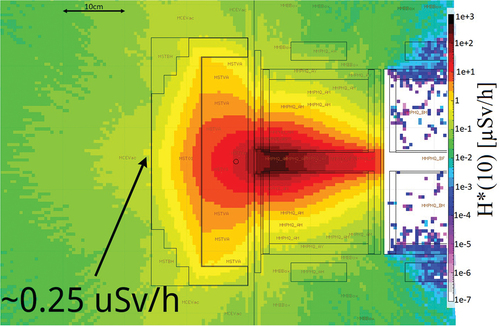
Small-size activated equipment (e.g., target holders, optical components, etc.) will be stored in a dedicated storage area until its activity decays below the exemption limitsCitation26 and the equipment is ready for reuse. A tracking database has been prepared for this purpose. An estimated time for the release of the item is provided, which is based on the initial dose measurements and expected nuclide inventory. Large items that cannot be dismounted are regularly monitored, and when needed, local shielding is added. shows an activation study of the first quadrupole in ELIMAIA after 1 year of operation and a 1 h cooldown. The ambient dose equivalent rate is significantly reduced when a stainless steel shielding block is added (see ). The shielding will be installed during upgrade and maintenance activities.
Fig. 11. Residual dose rate studies of the first quadrupole of ELIMAIA after 1 year of operation and 1 h of cooldown time. H*(10) rates in its proximity are significant. Extra shielding in this area was deemed necessary during maintenance and upgrade periods (see ).
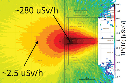
Fig. 12. Residual dose rate studies of the first quadrupole of ELIMAIA after 1 year of operation and 1 h of cooldown time with stainless steel shielding. H*(10) rates are significantly reduced with respect to the scenario without the shielding (see ).
To understand the long-term activation issues and to assess the decommissioning needs, Monte Carlo activation studies were performed for the bulky components of the experimental setups, including the beam dumps. A conservative approach was adopted for estimating the radionuclide inventory. It was assumed that the beamlines will operate at the maximum power for 8 h/day, 200 days/year for 25 years. Several cooling times were considered (10 min, 1 h, 1 day, 1 week, 1 month, and 1 year), as well as the possible presence of impurities. Based on these Monte Carlo studies, it is expected that short- and long-term activation will be an issue, particularly for steel components, which will contain relative isotopes such as 46Sc, 48V, 51Cr, 52Mn, 54Mn, 55Fe, 59F3, 55Co, 56Co, 57Co, 58Co, and 147Pm. On the other hand, the activation of concrete, polyethylene, granite, and aluminum structures is expected to decay under exemption limits in a short time interval. Based on these preliminary estimates, the activity of each beam dump will be approximately 1 GBq at the time of decommissioning. These expectations will be updated on the basis of more accurate simulations (refined geometry and source term descriptions) and will be integrated with repeated measurements of the activated parts.
A standalone and grinding topic is the radioactive contamination inside the interaction chambers originating from target debris. In fact, laser-target interactions are often destructive. Best practices and protocols for decontamination will be followed. However, since the radionuclide inventory of the contamination will be strongly dependent on the target and laser parameters, more dedicated studies are required. As a precaution, a post-experimental state has been introduced (see Sec. IX). The purpose of this mode is twofold: to allow short-lived radionuclides to decay and to give RP experts time to perform the necessary measurements and possible decontamination procedures before access is granted to other personnel.
In compliance with the legal requirements, an official plan for the decommissioning of ELI Beamlines was prepared by the RP group. It was approved by the national authority for radionuclide waste storage and its cost was calculated by an authorized company for reprocessing of radioactive materials. Once the decommissioning is completed, it is expected that it will be possible to use the premises without any restrictions. The decommissioning plan will be regularly reviewed and updated every 5 years.
IX. PERSONAL SAFETY INTERLOCK
The fundamental active layer of protection is the Personal Safety Interlock (PSI) system, which is intended to recognize the presence of hazards to personnel, initiate automatic protective measures, trigger alarms, and eliminate the hazard automatically, if possible. The covered hazards include, but are not limited to, ionizing radiation, laser, vacuum, and high voltage. In fact, the PSI is designed as an all-inclusive, redundant, fail-safe, independent electronic system compliant with an international standard for Functional Safety of Electronic Safety Systems.Citation58 Implementation, installation, and independent safety audits of the system have been outsourced to an external company.Citation59 However, the ELI Beamlines Safety Team prepared the conceptual design and was fully engaged in the risk assessments and definition of the safety functions.
A hybrid hardware-software-based solution was adopted. From system architecture, logic, and the software side, each experimental hall (with its unique set of hazards) is managed independently, but information from adjacent halls is shared. The system logic defines rules for the halls’ access and initiations of safety functions that prevent the occurrence of hazardous situations. In its simplified form, the PSI logic defines five operational modes: Clear, Alignment, High Power, Post Experiment, and Stop. Definitions and permissions for each state are clearly identified. For example, the Alignment mode means that a low-power laser can be present in the hall. There is no prompt radiation hazard, but there are laser-associated hazards. Authorized personnel are allowed in the hall with appropriate personal protection equipment: dosimeters (activation and conventional sources may be present) and laser goggles.
Instead, in the High Power mode the experiment is running. Access to the experimental hall is not allowed. All doors to the hall are locked by the PSI. If a door is forced open, the PSI reacts by shutting the safety gate valves of the laser beam transport, thereby stopping the laser from propagating to the hall. In Post Experimental mode, entrance to the hall is permitted only to the Radiation Officer or a designated deputy. They sweep the hall, assess the residual radiation risk level, and set the system to Clear mode by logging into the PSI.
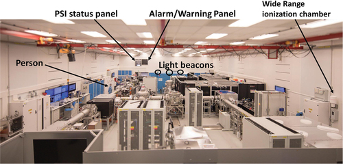
The hardware safety components of the PSI are safety gate valves regulating laser propagation, locks, limit switches for the access doors, flashing lights, audio broadcasting, and visualization panels informing about the operational status of the halls (). Finally, beam-off buttons are in the halls and control rooms for quick reactions to emergencies. Pressing a beam-off button cuts off the laser beam immediately, effectively stopping the experiment and bringing the hall to its Stop safe state.
Fig. 13. View of an experimental hall. Alarms, panels, and detectors are highlighted.
The PSI system is operated by using a touch screen panel and trapped keys located in the control room. Individual loggings with specifically defined roles for operators are required for access to the system. The PSI directly connects to other systems, including the radiation monitoring system described in Sec. X and the laser control system.
X. RADIATION MONITORING
X.A. Area Monitoring
In terms of surveillance of the current radiological situation, the PSI system relies on an online dose rate monitoring information system (MIS). The conceptual design, developed by the RP group, was implemented under its supervision by a consortium of external companiesCitation60–62 during the years 2019 to 2022. The MIS combines passive and active detector technologies to monitor prompt radiation levels, activation, and contamination in the workplace and surrounding areas. The detection systems were chosen considering both their capabilities and the intended measurement objectives, ranging from complex information needed in the high-occupancy areas (control rooms) to simple indicators providing early warnings in low-occupancy areas (plant rooms). Namely, three goals were identified: measuring prompt gamma and neutron dose rates, providing an early warning system, and measuring continuous radiation from activated materials.
Prompt gamma and neutron dose rates are measured in the high-occupancy areas (control rooms) or regularly accessed areas (corridors). A combined novel monitor for pulsed radiation, the LB-6419 (CitationRefs. 63, Citation64, and Citation65) is used. It comprises a helium-based proportional counter for neutron detection and a plastic scintillator for beta and gamma detection. Also, the characteristics of the radiation field in some locations has allowed for the installation of photon detectors only. A wide-range pressurized ionization chamberCitation66 was selected for this purpose.
Detectors for early warning have been implemented in the low-occupancy areas (plant rooms) and in the close vicinity of the interaction chambers for work during the Clear mode (see Sec. IX), when production of ionizing radiation is not expected but can still occur in the extremely rare case of the failure of several layers of protection. To detect prompt gamma and electron radiation, inorganic scintillators with aluminum-garnet crystals (Y3Al5G12:Ce and Lu3Al5G12:Ce) were chosen, since these crystal materials have been proven to have excellent scintillating properties even in harsh radiation environments.Citation67 Instead, prompt neutron radiation is detected by a proportional 3He counter inside a polyethylene sphere moderator (25-cm diameter). Possible activation in the experimental halls instead is monitored via Geiger-Müller countersCitation68 positioned in areas where high activation levels are expected
Information from all the monitoring detectors is collected, archived, and made available in real time in all the control rooms and remotely. Two signalization thresholds are set for emergency situations: warning and alarm. These are displayed and audibly announced directly in the halls and contemporarily signaled to the PSI, which takes the appropriate actions. The MIS is complemented by hand-held contamination monitors available in each experimental hall, a high-purity germanium spectrometer for detailed analysis in the central radiation laboratory, and a hand-foot monitor located at the exit from the controlled areas. Last, the online measurements are supported by the passive detection system based on optically stimulated luminescence dosimeters (see Sec. X.C).
X.B. Personal Dosimetry
A two-dosimeter rule is implemented at ELI Beamlines. Employees and users are requested to wear an electronic personal dosimeter (EPD) and a passive dosimeter. The EPDs (CitationRef. 69), which are sensitive to gamma and beta particles and provide a real-time measurement of personal deep [Hp(10)) and surface (Hp(0.07)] dose equivalent, were chosen for this purpose. Additionally, EPDs from the same manufacturer, but sensitive to gammas and neutrons, are also available. All EPDs have an active warning system (audible alarm) and internal memory for data retrieval. Readout and data analysis of the EPDs are performed inhouse, while regular calibrations are performed at the Czech Metrology InstituteCitation70 (CMI).
The EPDs are indeed capable of detecting a pulsed field (<1 µs and a repetition rate <1 kHz) (CitationRef. 69). Nevertheless, their reliability in pulsed radiation fields as demanding as those at ELI Beamlines is limited. Therefore, anyone accessing the radiation-controlled area is required to wear a film badge on their chest (reference point). This also fulfills the Czech legal requirement (see Sec. IV) that prescribes the use of certified and legally recognized dosimetry systems, film dosimetry being one of these. Film badges are prepared and readout at the Czech National Service for Dosimetry.
X.C. Area Dosimetry
Optically stimulated luminescence (OSL) dosimeters made of beryllium oxide (BeO) are usedCitation71,Citation72 for area photon dosimetry. BeO was chosen for its favorable dosimetric characteristics: high sensitivity to photon ionizing radiation, linear dose response over six orders of magnitude (µGy to Gy), and low effective atomic number (Zeff = 7.2), which makes it a near tissue-equivalent material.Citation73 Several thousand chips, each measuring 4.7 × 4.7 × 0.5 mm3, have been purchased and are placed throughout the entire laser building: halls, corridors, control rooms, and service areas. Evaluation is done inhouse, annealing is performed in a laboratory chamber furnace,Citation74 and readout is done using a Lexsyg smart reader.Citation75 Batch calibrations were performed at the Czech National Radiation Protection Institute (SÚRO, acronym in Czech), an accredited calibration laboratoryCitation76,Citation77 and at CMI (CitationRef. 70), a calibration laboratory. One benefit to using passive solid-state detectors is that, contrary to active detection systems, protection against EMPs is not necessary. Implementation of a passive neutron monitoring system is scheduled for the near future.
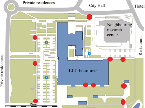
Finally, long-term environmental radiation monitoring using BeO OSL dosimeters around the facility premises is in place. ELI Beamlines is, in fact, located in an urban area, surrounded by public, private, and commercial buildings. Ten measuring locations have been selected in the parking lot and neighboring streets (see ). All dosimeters are evaluated quarterly. Systematic measurements started in 2018 after the initial measurement performed by the certified laboratory SÚRO (CitationRefs. 76, Citation77, and Citation78). Also, since the underground water table is quite high in the area, a dedicated study of the environmental impact of long-term potential activation was performed, while, standard protocols are also in place to monitor possible sources of air, water, and ground contamination.
Fig. 14. ELI Beamlines buildings and surrounding areas. The red dots mark the 10 environmental measuring points.
XI. CONCLUSIONS
The worldwide proliferation of high-power, high-intensity laser accelerators has opened a new chapter in the field of RP. The existing international standards and best practices used in conventional accelerator facilities cannot be directly applied to this new kind of facility, and new ones have not been firmly established yet. This paper reviews the challenges encountered and the adopted solutions while designing and implementing the RP system at the high-power, high-intensity laser facility ELI Beamlines. It comprises more than a decade of work and dedication from the RP group. This work may serve as a reference or an inspiration for new installations within this rapidly developing field.
The high-power, high-intensity laser facility laser, ELI Beamlines, poses considerable RP challenges. Wide penetrations in walls and ceilings are present to transport lasers and to house supporting technologies weakening the shielding elements. Therefore, ad hoc local shielding has been designed taking into account a combination of hazards: ionizing radiation, EMPs, and fire. The source term descriptions, needed for Monte Carlo simulations, are not as well known as in conventional accelerators and are subject to high uncertainty, requiring a conservative worst-case scenario approach. Laser-target interactions create strong EMPs, potentially damaging radiation detector electronics, thus a combination of active and passive detectors needs to be used. The experimental halls are clean rooms, significantly limiting available choices for shielding materials and the monitoring detectors that can be used; granite and coated concrete are effective options. The ultrashort laser pulses produce bursts of prompt radiation too short (up to ∼femtoseconds) to be reliably detected by conventional active dosimeters. The ELI Beamlines RP group is active in the testing and characterization of existing and newly developed detectors in ultrahigh pulse dose rate beam facilities. Finally, robust and redundant interlock and radiation monitoring systems are in place as fundamental layers of protection.
Disclosure Statement
No potential conflict of interest was reported by the author(s).
Additional information
Funding
References
- S. BACKUS et al., “High Power Ultrafast Lasers,” Rev. Sci. Instrum., 69, 3, 1207 (1998); https://doi.org/10.1063/1.1148795.
- “International Committee for Ultra-High Intensity Lasers,”; https://www.icuil.org ( current as of Dec. 12, 2022).
- C. DANSON et al., “Petawatt and Exawatt Class Lasers Worldwide,” High Power Laser Sci. Eng., 7, e54 (2019); https://doi.org/10.1017/hpl.2019.36.
- G. KORN et al., ELI –Extreme Light Infrastructure WHITEBOOK; Science and Technology with Ultra-Intense Lasers, THOSS Media GmbH, Berlin, Germany, (2011); https://eli-laser.eu/media/1019/eli-whitebook.pdf.
- W. LU et al., “Generating Multi-GeV Electron Bunches Using Single Stage Laser Wakefield Acceleration in a 3D Nonlinear Regime,” Phys. Rev. Spec. Top. Accel. Beams, 10, 6, 061301 (2007); https://link.aps.org/doi/10.1103/PhysRevSTAB.10.061301.
- W. P. LEEMANS et al., “Progress on Laser Plasma Accelerator Development Using Transversely and Longitudinally Shaped Plasmas,” C.R. Phys., 10, 2, 130 (2009); https://doi.org/10.1016/j.crhy.2009.05.001.
- M. ALLEN et al., “Proton Spectra from Ultraintense Laser–Plasma Interaction with Thin Foils: Experiments, Theory, and Simulation,” Phys. Plasmas, 10, 3283 (2003); https://doi.org/10.1063/1.1592154.
- T. COWAN et al., “Theoretical Understanding of Record Proton Energies from Laser Acceleration with Cone Targets and Future Prospects,” Proc. 2010 Advanced Accelerator Concepts Workshop, Annapolis, Maryland, June 13–19, 2010.
- “Council Regulation (EC) No 723/2009 of 25 June 2009 on the Community Legal Framework for a European Research Infrastructure Consortium (ERIC),” OJ L 206, p. 1, The Council of the European Union (Aug. 8, 2009).
- S. KÜHN et al., “The ELI-ALPS Facility: The Next Generation of Attosecond Sources,” J. Phys. B: At. Mol. Opt. Phys., 50, 132002 (2017); https://doi.org/10.1088/1361-6455/aa6ee8.
- S. GALES et al., “The Extreme Light Infrastructure-Nuclear Physics (ELI-NP) Facility: New Horizons in Physics with 10 PW Ultra-Intense Lasers and 20 MeV Brilliant Gamma Beams,” Rep. Prog. Phys., 80, 094301 (2018); https://doi.org/10.1088/1361-6633/aacfe8.
- B. RUS et al., “Outline of the ELI-Beamlines Facility,” Proc. SPIE 8080, Prague, Czech Republic, June 9, 2011; https://doi.org/10.1117/12.890392.
- “ ELI, the Extreme Light Infrastructure ERIC,” ELI Beamlines Research Programs; https://www.eli-beams.eu/about/projects/completed-projects/eli/research-programs/ ( current as Feb. 23, 2023).
- R. ANTIPENKOV et al., “The Construction of Allegra Kilohertz Femtosecond Laser System at ELI-Beamlines,” Proc. SPIE 11034, Prague, Czech Republic, April 26, 2019; https://doi.org/10.1117/12.2524436.
- J. T. GREEN, R. ANTIPENKOV, and P. BAKULE, “L2-DUHA 100 TW High Repetition Rate Laser System at ELI-Beamlines Key Design Considerations,” Reza Kenkyu, 49, 2, 106 (2021).
- E. SISTRUNK et al., “All Diode-Pumped, High-Repetition-Rate Advanced Petawatt Laser System (HAPLS),” Proc. Conf. on Lasers and Electro-Optics, p. 1, San Jose, California, May 14–16, 2017 (2017); https://doi.org/10.1364/CLEO_SI.2017.STh1L.2.
- F. BATYSTA et al., “Spectral Pulse Shaping of a 5 Hz, Multi-Joule, Broadband Optical Parametric Chirped Pulse Amplification Frontend for a 10 PW Laser System,” Opt. Lett., 43, 16, 3866 (2018); https://doi.org/10.1364/OL.43.003866.
- O. HORT et al., “High-Flux Source of Coherent XUV Pulses for User Applications,” Opt. Express, 27, 6, 8871 (2019); https://doi.org/10.1364/OE.27.008871.
- J. NEJDL et al.,” Progress on Laser-Driven X-ray Sources at ELI Beamlines,” Proc. SPIE 11111, San Diego, California, September 9, 2019; https://doi.org/10.1117/12.2532702.
- U. CHAULAGAIN et al., “ELI Gammatron Beamline: A Dawn of Ultrafast Hard X-ray,” Sci. Photonics, 9, 11, 853 (2022); https://doi.org/10.3390/photonics9110853.
- A. MOLODOZHENTSEV et al., “LWFA-Driven Free Electron Laser for ELI-Beamlines,” Proc. 60th ICFA Advanced Beam Dynamics Workshop (FLS’18), p. 62, Shanghai, China, March 5–9, 2018 (2008); https://doi.org/10.18429/JACoW-FLS2018-TUA2WC02.
- G. GRITTANI et al., “ELI-ELBA: Fundamental Science Investigations with High Power Lasers at ELI-Beamlines,” in OSA High-Brightness Sources and Light-Driven Interactions Congress 2020 (EUVXRAY, HILAS, MICS), L. ASSOUFID et al., Eds., paper JM3A.20, OSA Technical Digest Optica Publishing Group (2020); https://doi.org/10.1364/EUVXRAY.2020.JM3A.20.
- C. LAZZARINI et al., “50 MeV Electron Beams Accelerated by a Terawatt Scalable kHz Laser,” arXiv:2302.11415 [physics.plasm-ph] (2023); https://doi.org/10.48550/arXiv.2302.11415.
- M. TRYUS et al., “TERESA Target Area at ELI Beamlines,” Quantum Beam Sci., 4, 4, 37 (2020); https://doi.org/10.3390/qubs4040037.
- D. MARGARONE et al., “ELIMAIA: A Laser-Driven Ion Accelerator for Multidisciplinary Applications,” Quantum Beam Sci., 2, 2, 8 (2018); https://doi.org/10.3390/qubs2020008.
- S. WEBER et al., “P3: An Installation for High-Energy Density Plasma Physics and Ultra-High Intensity Laser–Matter Interaction at ELI-Beamlines,” Matter Radiat. Extremes, 2, 4, 149 (2017); https://doi.org/10.1016/j.mre.2017.03.003.
- “ Atomic Law,” Státní úřad pro jadernou bezpečnost; https://www.sujb.cz/legislativa/atomove-pravo ( current as of Dec. 13, 2022) (in Czech).
- “The 2007 Recommendations of the International Commission on Radiological Protection,” ICRP Publication 103. Ann. ICRP 37(2-4), International Commission on Radiological Protection (2007).
- “Council Directive 2013/59/Euratom of 5 December 2013 Laying Down Basic Safety Standards for Protection Against the Dangers Arising from Exposure to Ionising Radiation, and Repealing Directives 89/618/Euratom, 90/641/Euratom, 96/29/Euratom, 97/43/Euratom and 2003/122/Euratom,” OJ L 013 17.1.2014, p. 1, European Atomic Energy Community (2013).
- “Recommendations of the ICRP,” ICRP Publication 26, Ann. ICRP 1(3): 1, International Commission on Radiological Protection (1977).
- “ISO 14644-1:2015. Cleanrooms and Associated Controlled Environments—Part 1: Classification of Air Cleanliness by Particle Concentration,” International Organization for Standardization (2015); https://www.iso.org/standard/53394.html.
- C. AHDIDA et al., “Capabilities of the FLUKA Multi-Purpose Code,” Front. Phys., 9, 788253 (2022); https://doi.org/10.3389/fphy.2021.788253.
- G. BATTISTONI et al., “Overview of the FLUKA Code,” Ann. Nucl. Energy, 82, 10, 10 (2015); https://doi.org/10.1016/j.anucene.2014.11.007.
- F. BORNE et al., “Radiation Protection for an Ultra-High Intensity Laser,” Radiat. Prot. Dosim., 102, 1, 61 (2002); https://doi.org/10.1093/oxfordjournals.rpd.a006074.
- P. L. PRITCHETT, “Particle-in-Cell Simulation of Plasmas—A Tutorial,” Space Plasma Simulation. Lecture Notes in Physics, Vol. 615, J. BÜCHNER, M. SCHOLER, and C. T. DUM, Eds., Springer (2003); https://doi.org/10.1007/3-540-36530-3_1.
- W. BANG et al., “Review of Laser-Plasma Physics Research and Applications in Korea,” J. Korean Phys. Soc., 80, 698 (2022); https://doi.org/10.1007/s40042-021-00391-w.
- G. MILOSHEVSKY, “Ultrafast Laser Matter Interactions: Modelling Approaches, Challenges, and Prospects,” Modell. Simul. Mater. Sci. Eng., 30, 083001 (2022); https://doi.org/10.1088/1361-651X/ac8abc.
- F. CONSOLI et al., “Laser Produced Electromagnetic Pulses: Generation, Detection and Mitigation,” High Power Laser Sci. Eng., 8, e22, 59 (2020); https://doi.org/10.1017/hpl.2020.13.
- K. NELISSEN et al., “Characterisation and Modelling of Ultrashort Laser-Driven Electromagnetic Pulses,” Sci. Rep., 10, 3108 (2020); https://doi.org/10.1038/s41598-020-59882-8.
- V. SHURENKOV and V. PERSHENKOV, “Electromagnetic Pulse Effects and Damage Mechanism on the Semiconductor Electronics,” Facta Univ. Ser.: Elec. Energ., 29, 621 (2016); https://doi.org/10.2298/FUEE1604621S.
- “ISO/TS 18090-1: 08-2015.Radiological Protection - Characteristics of Reference Pulsed Radiation—Part 1: Photon Radiation,” International Organization for Standardization (2015); https://www.iso.org/standard/61352.html.
- T. WERNER et al., “Dose Rate Measurements in Pulsed Radiation Fields by Means of an Organic Scintillator,” Proc. EPJ Web. Conf., 253, 09002 (2021); https://doi.org/10.1051/epjconf/202125309002.
- U. ANKERHOLD et al., “Deficiencies of Active Electronic Radiation Protection Dosemeters in Pulsed Fields,” Radiat. Prot. Dosim., 135, 3, 149 (2009); https://doi.org/10.1093/rpd/ncp099.
- A. SCHÜLLER et al., “The European Joint Research Project UHDpulse—Metrology for Advanced Radiotherapy Using Particle Beams with Ultra-High Pulse Dose Rates,” Phys. Med., 80, 134 (2020); https://doi.org/10.1016/j.ejmp.2020.09.020.
- G. ZORLONI et al., “Intercomparison of Personal and Ambient Dosimeters in Extremely High-Dose-Rate Pulsed Photon Fields,” Radiat. Phys. Chem., 172, 108764 (2020); https://doi.org/10.1016/j.radphyschem.2020.108764.
- J. T. WALLMARK and S. M. MARCUS, “Minimum Size and Maximum Packing Density of Nonredundant Semiconductor Devices,” Proc. IRE, 50, 3, 286 (Mar. 1962); https://doi.org/10.1109/JRPROC.1962.288321.
- I. EFTHYMIOPOULOS et al., “First Year of Physics at CNGS,” Proc. Particle Accelerator Conf. 2009, p. TU6PFP079, Vancouver, Canada, May 4–8, 2009 (2009).
- M. BAGATIN and S. GERARDIN, Ionizing Radiation Effects in Electronics: From Memories to Imagers, CRC Press Taylor & Francis Group (2018).
- R. GARCIA ALIA et al., “Single Event Effects in High-Energy Accelerators,” Semicond. Sci. Technol., 32, 034003 (2017); https://doi.org/10.1088/1361-6641/aa5695.
- S. UZNANSKI et al., “Qualification of Electronics Components for a Radiation Environment: When Standards Do Not Exist,” Proc. RADECS Short Course, Part 4B, p. 1, Geneva, Switzerland, October 2017; https://doi.org/10.23919/MIXDES.2018.8436726.
- “RADiation facility Network for the EXploration of effects for indusTry and research,” RADNEXT; https://radnext.web.cern.ch ( current as of Mar. 6, 2023).
- FLUKA Manual, “5.1 Particles Codes, ‘List of Particles Transported by FLUKA,’” CERN; https://flukafiles.web.cern.ch/manual/chapters/particle_and_material_codes/particles_codes.html ( current as of Mar. 6, 2023).
- V. VLACHOUDIS, “FLAIR: A Powerful but User Friendly Graphical Interface for FLUKA,” Proc. Int. Conf. on Mathematics, Computational Methods & Reactor Physics (M&C 2009), Saratoga Springs, New York (2009).
- V. OLŠOVCOVÁ et al., “Bulk Shielding for Laser Research Centre ELI Beamlines,” Prog. Nucl. Sci. Technol., 4, 247, 247 (2014); https://doi.org/10.15669/pnst.4.247.
- “Jabroc ‘N’ Densified Wood Laminate,” DEHOMIT; http://www.dehonit.com.cn/english/zuihou.html ( current as of Mar. 3, 2023).
- R. BARMAN et al., “Investigation of Radiation Shielding Characteristic Features of Different Wood Species,” Radiat. Phys. Chem., 192, 109927 (2022); https://doi.org/10.1016/j.radphyschem.2021.109927.
- A. FASSO et al., “An Activation Database for Materials Used at High Intensity Laser Acceleration Facilities,” Proc. Shielding Aspects of Accelerator, Target and Irradiation Facilities (SATIF-13), p. 422, October 10–12, 2016, Dresden, Germany, NEA/NSC/R2(2018), Organisation for Economic Co-operation and Development (2018).
- “IEC 61580:2010. Functional Safety of Electrical/Electronic/Programmable Electronic Safety-related Systems,” International Eletrotechnical Commission (2010).
- “Welcome,” Rockwell Automation; https://www.rockwellautomation.com ( current as of Dec. 13, 2022).
- “Your Lifecycle Partner Providing Innovative Solutions Across Engineering, Services and Products—Securing Your Performance in Heavily Regulated Environments,” Nuvia; https://www.nuvia.com ( current as of Dec. 13, 2022).
- “Detection and Measurement of Radiation,” VF Nuclear; https://www.vfnuclear.com ( current as of Dec. 13, 2022).
- “Nuclear & Environmental,” Canberra Packard; https://www.cpce.net ( current as of Dec. 13, 2022).
- A. KLETT et al., “A Dose Meter for Pulsed Neutron Fields,” Radiat. Meas., 45, 10, 1242 (2010); https://doi.org/10.1016/j.radmeas.2010.06.008.
- A. LEUSCHNER, “Dose Rate Measurements Around the Electron Extraction at FLASH,” Proc. 8th Int. Workshop on Radiation Safety at Synchrotron Radiation Sources (RadSynch15), Hamburg,DESY, Germany, June 3–5, 2015.
- “Process Control, Bioanalytics, Radiation Protection,” Berthold Technologies; https://www.berthold.com ( current as of Dec. 13, 2022).
- “FHT 192 Ionization Chambers,” ThermoFisher;https://www.thermofisher.com/order/catalog/product/425354050?SID=srch-srp-425354050 ( current as of Dec. 13, 2022).
- M. T. LUCCHINI et al., “Radiation Tolerance of LuAG:Ce and YAG:Ce Crystals Under High Levels of Gamma- and Proton-Irradiation,” IEEE Trans. Nucl. Sci., 63, 2, 586 (Apr. 2016); https://doi.org/10.1109/TNS.2015.2493347.
- “VF Nuclear Gamma Detectors,” VF Nuclear; https://www.nutronic.se/mdg-0x-series-dose-rate-meters ( current as of Mar. 24, 2023).
- “Thermofisher Electronic Personal Dosimeter TruDose,” ThermoFisher; https://www.thermofisher.com/order/catalog/product/EPDTRUDOSE ( current as of Dec. 13, 2022).
- “Český Metrologický Institut,”; https://www.cmi.cz ( current as of December 13, 2022) (in Czech).
- E. G. YUKIHARA et al., “Luminescence Dosimetry,” Nat. Rev. Meth. Primers, 2, 26 (2022); https://doi.org/10.1038/s43586-022-00102-0.
- E. BULUR and H. Y. GÖKSU, “OSL from BeO Ceramics: New Observations from an Old Material,” Radiat. Meas., 29, 639 (1998); https://doi.org/10.1016/S1350-4487(98)00084-5.
- E. G. YUKIHARA, A. B. ANDRADE, and S. ELLER, “BeO Optically Stimulated Luminescence Dosimetry Using Automated Research Readers,” Radiat. Meas., 94, 27 (2016); https://doi.org/10.1016/j.radmeas.2016.08.008.
- “Furnaces and Dryers,” LAC, s.r.o; https://www.lac.cz/en/ ( current as of Dec. 13, 2022).
- “Luminescence Measurement Devices,” Freiberg Instruments; https://www.lexsyg.com/tlosl-reader.html ( current as of Dec. 13, 2022).
- “Státní ústav radiační ochrany”; https://www.suro.cz ( current as of Dec. 13, 2022) (in Czech).
- “ISO/IEC 17025:2017. General Requirements for the Competence of Testing and Calibration Laboratories,” International Organization for Standardization (2017); https://www.iso.org/standard/66912.html.
- A. CIMMINO et al., “Characterization of OSL Dosimeters Used at the ELI-Beamlines Laser-Driven Accelerator Facility,” J. Radiol. Prot., 41, N23 (2021); https://doi.org/10.1088/1361-6498/ac14d5.