
 ?Mathematical formulae have been encoded as MathML and are displayed in this HTML version using MathJax in order to improve their display. Uncheck the box to turn MathJax off. This feature requires Javascript. Click on a formula to zoom.
ABSTRACT
The mechanisms of densification in spark plasma sintering (SPS) were investigated both analytically and numerically for a model system of two spherical metallic powder particles. From the microscopic temperature distribution, the possibility of a micro-local overheating of the particle–particle contacts was analysed for different particle sizes, contact geometries, materials, and electrical loads. It is shown that, for particles below the size of one millimetre, local overheating is below one Kelvin. Subsequently, the material transport by thermomigration, electromigration, and diffusion driven by surface curvature and external pressure was derived from microscopic field distributions obtained from analytical calculations and finite-element simulations. The results show that, while the mechanical pressure accelerates material transport by orders of magnitude, the electrical current and the temperature gradients do not. It is also shown that pulsing the current has no significant influence on the densification rate.
1. Introduction
The technique of densifying powders by heating them with an electrical current and simultaneously applying a mechanical pressure is called spark plasma sintering (SPS), if (i) the pressure is in the order of ten megapascal, (ii) the voltage is between one to ten volt, and the electrical current both (iii) in the order of 100–1000 ampere (some A/mm) and (iv) pulsed in the millisecond range. The application of a mechanical pressure allows lower sintering temperatures and makes SPS a very powerful technique, especially for the fabrication of nano-structured materials or for the densification of temperature sensitive phases [Citation1,Citation2]. In the majority of research papers addressing this topic, SPS is used as fast and reliable method to synthesise and densify a huge variety of materials like metals, metallic glasses, cemented carbides, ceramics, or functional graded materials [Citation3].
Referring to the low sintering temperature, additional densification mechanisms despite the pressure have been proposed, leading to the name spark plasma sintering. The 'spark plasma effect' supposedly consists of (i) spark discharges, (ii) plasma formation, (iii) surface oxide removal, (iv) electromigration, (v) thermomigration, (vi) an increased defect concentration, (vii) enhanced defect mobility, and (viii) local overheating up to melting of the contacts between the powder particles. Most research papers reduce the assessment of 'how it works' to introductory comments about this technique being superior due to the 'spark plasma effect'. Only a limited number of fundamental studies about SPS mechanisms have been published. While all the constituents of the 'spark plasma effect' exist and have been thoroughly studied, the conditions under which they are observed do not necessarily match SPS process parameters. Plasma, for example, was observed at elevated voltages [Citation4] whereas its absence has been reported under SPS conditions [Citation4–6]. Sparks have been observed only for 500 μm large particles, only for a current density ten times larger than used in SPS, only for low mechanical pressure and only during the first few milliseconds of current flow [Citation7]. Still, and to some extent owed to the huge variety of materials SPS deals with, some recent reviews and book chapters [Citation8,Citation9] address the fast densification in SPS to these phenomena.
The authors have therefore decided to publish a set of three papers dealing with densification mechanisms of metallic materials in SPS. The first paper [Citation10] discussed the current flow through the macroscopic system (powder compact/punch/die), the generation of Joule heat, and the resulting macroscopic temperature distribution for several conditions and changing resistance of the powder compact during compaction. The paper revealed that more than 90% of the Joule heat originates from the graphite punches that act as heating element for the powder compact. Also, the current flowing through the metallic powder compact is in most situations independent of the powder compacts resistivity, i.e. its degree of densification. This is a consequence of the tool geometry: the graphite punches have a small diameter and consequently a high electrical resistance, while the graphite die has a larger diameter and therefore a low resistance. The latter acts as parallel electrical load to the powder compact. Trying to describe SPS using a constant voltage drop over a model unit of the powder compact can therefore easily lead to faulty results like an overestimation of both the current flow through the system and the microscopic temperature inhomogeneity.
By starting with a constant current flowing through the powder compact during densification, the present paper at first introduces an analytical model for the microscopic temperature homogeneity, i.e. the overheating of the particle-particle contacts with respect to the centre of the particles. This temperature difference between particle contact and particle centre will be called supertemperature, a term stemming from contact physics were comparable problems have been analysed decades ago [Citation11,Citation12]. The model is then used to assess the influence of current density, particle size, relative neck size (representing applied pressure and densification), and material properties on the supertemperature. The applicability of the analytical model is confirmed by results from finite-element simulations, whereby the model used for the simulations has been proven earlier to be able to reproduce experimental results [Citation13]. Subsequently, maximal densification rates caused by surface curvature and external pressure driven diffusion, electro- and thermomigration are calculated. After analysing the plausibility of different routes for material transport, realistic densification rates are attributed to each mechanism under consideration, taking into account accurate temperature and electric field distributions from the finite-element simulations. Results from other research groups are critically reviewed.
The last paper of this series will focus on describing the most relevant processes of densification of the powder compact by plastic deformation and creep.
2. Microscopic temperature distribution: a simplified analytical model
For a tool with punches and die made from the same type of graphite, a fraction of 40 to 60% of the total electric current flows through the electrical conductive powder compact if its resistivity is sufficiently low [Citation10]. If all the particle-particle contacts are assumed equal, this fraction of the current does not change despite further densification of the powder compact. This leads to a defined current through each particle-particle contact, whereby in real systems, initially some preferred paths for the current flow can form, resulting in an increased local current density [Citation14]. On the microscopic scale, the Joule heating per unit volume is defined by the local resistivity
, and the square of the local current density
. As the current density is amplified when the current is forced through the narrow contact zone where one particle touches the other, a large amount of heat is expected to stem from this contact zone. Depending on how fast the heat is conducted away towards the centre of the particles, the contact is expected to be hotter than the centre. The magnitude of this supertemperature should increase when a small relative contact radius leads to a high local current density and when the thermal conductivity of the (bulk) material is low. If the current through the particles is kept constant and the contact radius is reduced close to a point contact, an almost infinite contact overheating would theoretically become possible, justifying the word 'plasma' as part of the name spark plasma sintering. Realistic values will be derived in this section.
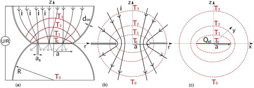
Figure (a) schematically shows two powder particles in contact with each other after plastic deformation caused by the applied mechanical load. In the most complicated case, the oxide layer has partially been cracked. Only small metallic contact spots – with that have been formed in the cracks of the oxide layer - allow the current flow. This is typically the case for thicker and non-conducting to weakly conducting oxide layers. If the oxide layer stays intact, it presents an additional film resistance for the electrical current but the latter flows homogeneously through the whole contact [Citation12,Citation15,Citation16]. In any case, the electrical current leads to an inhomogeneous temperature distribution in the powder particle, whereby the highest temperature,
, can be found at z = 0. From there on the temperature decreases towards the centre of the particle, with
. For the case of electrical contact spot formation, shown in Figure (a), despite tiny hot-spots in the direct vicinity of these contact spots, the temperature distribution in the particle is similar to that shown in Figure (b). In the latter case, the radius of the conducting contact a corresponds to the contact radius in Figure (a). No current is allowed through the contact plane for r > a. The latter problem can be solved more or less analytically [Citation17], but the solution is impractical for clearly showing the impact of current intensity, contact radius, etc. on the micro-local temperature distribution.
Figure 1. (a) Schematic representation of the 'worst case' of a realistic particle-particle contact with a surface oxide layer partially cracked in the contact zone and the current flowing through conducting spots formed along these cracks. (b) Sophisticated model-system describing volumetric electric heating of the material around a small conductive zone where the current is forced through between two electrically insulated semi-infinite bodies. (c) Simplified model with a circular heat source representing the Joule heat inside an infinite body.
To understand the contact overheating and the processes during pulsed current heating, it is reasonable to use a simplified but sufficiently accurate model as shown in Figure (c). A comparison with more sophisticated models depicted in Figure and with selected results of finite-element simulation (c.f. Section 3) show the accuracy of the calculations. The model assumes a small circular spot with radius a - that corresponds to the neck radius between the two particles – acting as heat source in an infinite body. Chapter 10.5-III in Carslaw and Jaeger's book [Citation18] gives a solution for the problem, were all the Joule heat originates from the electrical conducting circle with an area of
, with
. This differs from the electric contact heating where the volume around the contact plane is heated as the current is more and more confined. The temperature far away from the contact is kept constant at
. For the two-particle model, this would mean the temperature in the centre of the particle is not being altered during the short current pulse (this is usually not true but only leads to an overestimation of the supertemperature). It is assumed that during one pulse the temperature would not be increased too much so that constant material parameters can be used. Using Carslaw and Jaeger's solution, the contact temperature as function of the time t and the distance from the contact plane z can be calculated by:
(1)
(1) with the thermal conductivity λ and the temperature conductivity α. The heat source
, the Joule heat, is generally time dependent, if current density, contact radius, and resistivity change with varying temperature. During the short time of one single current pulse (in the order of ten milliseconds) it is safe to assume that these parameters are constant [Citation19]. If only the heat generated inside of the powder compact is considered, i.e. neglecting any heating from the graphite punches, the contact resistance,
, is responsible for more than 90% of the powder particles' resistance and therefore heat generation [Citation20]. The contact resistance is the sum of (i) the constriction resistance that originates from the current being forced through the small contact area,
, that depends on the electrical resistivity of the bulk material
and the contact radius a and (ii) the film resistance if an intact oxide layer is present, whereby
depends on the electrical resistivity
and thickness
of the oxide layer as well as the contact radius.
can than be calculated using the current through the single contact
by:
(2)
(2) For very thin oxide layers, the tunnel resistance has to be taken into account instead [Citation21]. Combining Equations (Equation1
(1)
(1) ) and (Equation2
(2)
(2) ) and rearranging them so that the content of the square brackets becomes 1 for larger times t reveals the temperature in the contact plane for z = 0:
(3)
(3)
Figure 2. Temperature in the particle contact area normalised by the maximal contact temperature in the stationary state displayed as function of τ that includes material parameters and contact radius (). The experimentally verified models developed for volumetric heating by a current passing through the contact spot [Citation11,Citation17] show a satisfying accuracy of the simplified model used in the present publication.
![Figure 2. Temperature in the particle contact area normalised by the maximal contact temperature in the stationary state displayed as function of τ that includes material parameters and contact radius (τ=λ/(ρa2) t). The experimentally verified models developed for volumetric heating by a current passing through the contact spot [Citation11,Citation17] show a satisfying accuracy of the simplified model used in the present publication.](/cms/asset/89eef99e-d10b-4004-b47b-63b009e0fe7a/ypom_a_1829349_f0002_oc.jpg)
The evolution of the contact temperature – as function of a material and geometry independent parameter – is shown in Figure . It is in good agreement with more sophisticated models that are based on the problem depicted in Figure (b). After some time, the result of Equation (Equation3
(3)
(3) ) becomes stationary. The duration of the instationary phase depends on the size of the contact area and on the thermal conductivity and density of the material. Typical times are given in Table for copper, for the martensitic steel X46Cr13, and for the austenitic steel 304L as well as for different contact radii. Iron-based materials will of course usually be austenitic at sintering temperature. If stationary conditions are assumed as soon as 90% of the final (stationary) contact temperature is reached, the instationary phase would be 40 μs for copper, 0.6 ms for the martensitic steel, and 1.3 ms for the austenitic steel if an contact radius of 10 μm is assumed. This times scale with
so that an almost immediate stationary contact temperature can be assumed for typical powder particles with a particle radius smaller than 50 μm.
Table 1. Time in milliseconds until 90% of the stationary contact-temperature is reached ( ) for copper, martensitic, and austenitic steel.
As measure for the temperature inhomogeneity, the temperature difference between the hottest and the coldest points (the particle contacts and the centre of the particles) is used, i.e. . This temperature difference is called the supertemperature. When the stationary state is reached,
becomes:
(4)
(4)
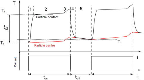
This stationary phase will only hold until the heat reaches the centre of the particles, as the model assumes conductive cooling to an infinite body. In total, the evolution of the temperature in the particle contacts and the centre during pulsed current heating can be divided into five stages that are schematically depicted in Figure . As the major part of the heat is generated in the contact, the temperature there is almost initially increased by , see Table . This is the non-stationary phase. Eventually, the stationary solution will be applicable, until the heat reaches the centres of the particles. Until this moment, the latter approximately keep the starting temperature
. From now on, the temperature in the whole particle rises, while the supertemperature
may slightly change with time if temperature dependent properties are taken into account [Citation13]. During
, when no current flows, the contact area cools down and the heat is distributed to the whole particle, increasing its temperature to a value slightly higher than
. In the last stage, the whole specimen cools down due to radiation mostly from the surface of the graphite die and due to conduction to the cooled electrodes. The particle reaches the new starting temperature
which is barely higher than
as the 'overheated' volume of the contact is only a small fraction of the particle's total volume. As an example, by considering a heating rate of 1000 K/min, the mean temperature increase during 15 ms (10 ms pulse plus 5 ms pause time) is
K.
Figure 3. Schematic representation of the temperature evolution in the contact zone between two particles (black) as well as in the centre of the particle (red) during heating by a pulsed electric current. After an instationary phase when only the particle contacts are heated up (1) the generation of heat in the contact and its dissipation become equal (2, stationary phase). Still the centre of the particle is only slightly heated by the low current density passing through it. As soon as the heat front reaches the centre, the whole particle is heated up more or less equally (3, it deviates from being equally heated only because of the temperature dependent material parameters). When the current is turned of, the temperature in the contact zone rapidly decreases (4) until the whole particle will have a uniform temperature distribution, cooling slowly by heat loss through the electrodes or radiation from the surface of the die (5).
2.1. Supertemperature for different materials
The supertemperature calculated using Equation (Equation4(4)
(4) ) is given in Figure as a function of the current through a single contact,
, for copper, martensitic steel, and austenitic steel using the material properties given in Table [Citation22,Citation23]. The values are calculated for powder particles with
μm and a relative neck radius of
. The current density is defined by the sintering temperature or the heating rate, respectively [Citation10]. As an example, the top scale gives the total current through the specimen for a powder compact with a diameter of 15 mm densified using a HPD5 SPS machine manufactured by FCT Systeme GmbH (Rauenstein, Germany). The two vertical lines in Figure correspond to (i) a fraction of 40% of the total current intensity of 320 A as it is needed for sintering copper at
C (128 A [Citation10] represented by the thin black line) and (ii) 5000 A as the limit of the machine used represented by the thick red line. It can be seen that for this typical particle size, the contacts of copper particles are only
to
K hotter than their centre. Owing to the high electrical resistivity and the low thermal conductivity of the austenitic stainless steel, a supertemperature of up to 1 K can occur in this material. As the supertemperature increases with the contact current by
, a notable microscopic temperature inhomogeneity can only be achieved for current densities at least one order of magnitude higher than used in SPS machines. Even with a pulsed current, such current densities can not be realised by commercially available SPS apparatuses [Citation10].
Figure 4. Supertemperature for different materials as a function of the current flowing through each particle-particle contact. The top scale shows approximately the currents through a powder compact of 15 mm diameter as well as the current density. The vertical lines indicate, for the same sample size, (i) the current through the specimen corresponding to the densification of copper at C when 40% of the total current of 320 A flow through the specimen [Citation10]), and (ii) the limit of the machine when all the current is assumed to flow through the sample (5000 A, thick red line). The different current assisted techniques (i) spark plasma sintering, (ii) flash spark plasma sintering (FSPS), (iii) electro-resistive sintering (ERS) and (iv) capacitor discharge compaction (CD) are given indicating the current density used for these processes. It can be seen that contact melting can be achieved for high current ERS or CD only. Note that the values are calculated for temperature independent material parameters. They will increase much faster than shown for higher supertemperatures (
K) and negative temperature coefficient of the resistivity.
![Figure 4. Supertemperature for different materials as a function of the current flowing through each particle-particle contact. The top scale shows approximately the currents through a powder compact of 15 mm diameter as well as the current density. The vertical lines indicate, for the same sample size, (i) the current through the specimen corresponding to the densification of copper at 600∘C when 40% of the total current of 320 A flow through the specimen [Citation10]), and (ii) the limit of the machine when all the current is assumed to flow through the sample (5000 A, thick red line). The different current assisted techniques (i) spark plasma sintering, (ii) flash spark plasma sintering (FSPS), (iii) electro-resistive sintering (ERS) and (iv) capacitor discharge compaction (CD) are given indicating the current density used for these processes. It can be seen that contact melting can be achieved for high current ERS or CD only. Note that the values are calculated for temperature independent material parameters. They will increase much faster than shown for higher supertemperatures (>100 K) and negative temperature coefficient of the resistivity.](/cms/asset/88e7c0ab-da8f-4e63-9734-d90a80f75e2c/ypom_a_1829349_f0004_oc.jpg)
Table 2. Temperature dependent material properties for pure copper (top) and 304 stainless steel (bottom).
2.2. Influence of particle size and densification on the supertemperature
Besides the effect of current intensity on temperature inhomogeneity, the influence of particle size and the size of the contact can be easily assessed from Equation (Equation4(4)
(4) ). For copper powder particles with a relative neck radius of
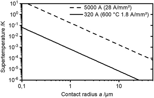
, Figure shows the influence of particle size on the supertemperature. Even powder particles in the millimetre range and the maximum current intensity of the SPS device are not enough for a supertemperature of some Kelvin. The top curve (short dashed line) of Figure shows results for a current density achievable in our custom-made lab-scale SPS machine and the corresponding FE simulations [Citation20] to demonstrate the accuracy of the simplified analytical model (the FE values are about a factor of two smaller than the analytically derived ones). Similarly, Figure clearly shows that the contact radius for a copper powder particle with a particle radius of
μm has to be reduced close to a point contact to realise a relevant supertemperature. Given that for copper a relative neck size of
is already achieved using a mechanical pressure of 10 MPa at room temperature, besides bad electric contacting, this would mean to totally yield up the advantages of pressure assisted densification.
Figure 5. Impact of changing particle radius on the supertemperature. The total current is fixed but the current through each contact changes while the current density is constant. Results from FE simulations marked with X are shown for comparison. The very high current density matches a custom-made lab-scale SPS apparatus used for the corresponding experiments [Citation20]). These results deviate by a factor of two from the calculated results using Equation (Equation4(4)
(4) ).
![Figure 5. Impact of changing particle radius on the supertemperature. The total current is fixed but the current through each contact changes while the current density is constant. Results from FE simulations marked with X are shown for comparison. The very high current density matches a custom-made lab-scale SPS apparatus used for the corresponding experiments [Citation20]). These results deviate by a factor of two from the calculated results using Equation (Equation4(4) ΔT=RcIc2πaλ.(4) ).](/cms/asset/a80a38ca-aa01-4585-a7b6-732c0cda144f/ypom_a_1829349_f0005_oc.jpg)
Figure 6. Impact of growing contact radius (densification) on the supertemperature. The total current as well as the current through each contact is fixed while the current density in the contact decreases.
2.3. Conclusions regarding the microscopic contact supertemperature
Despite the microscopic temperature inhomogeneity being frequently mentioned in reviews, books or typically in the introduction of research papers, primary sources for analytical, numerical or experimental results showing a largely increased temperature in the particle-particle contacts are surprisingly hard to find. The high supertemperature is usually the result of either an adiabatic calculation (no heat conduction) and a small neck radius down to a point contact [Citation7,Citation24] or very high electrical loads. If the latter ones are reduced to values achievable in SPS, the supertemperature decreases to less than 1 K [Citation25–27]. Other research explicitly states minimal supertemperatures for real SPS conditions or an extrapolation to those [Citation13,Citation19,Citation28–31]. Scarce experimental data for large current densities support this findings [Citation10,Citation19,Citation32]. The results obtained from analytical calculations confirmed by FE simulations support the finding of minimal supertemperatures. For typical conditions and metallic powders, the supertemperature is below K. Only if a very small mechanical pressure, an electrically insulating die, and powder particles close to the size of a millimetre are used, the maximum current strength of SPS machines can lead to a significant overheating of the contacts.
For smaller particles and higher mechanical pressures, considerably higher current intensities are necessary to enhance densification by overheating the particle-particle contacts, as indicated in Figure . Capacitor discharge (CD) techniques are a typical application that apply a higher voltage of up to 100 V which is almost fully delivered to the specimen, as punches made from metal (often copper based) instead of graphite are used. The resulting current intensities of up to are forced through the sample by using an electrically insulated die. In this case, the densification of the powder compact can be achieved within milliseconds and at least assisted by partially melting of the particles, as it has been shown for steel [Citation33],
[Citation34], as well as other metallic materials which could be fully densified [Citation35]. As another example, a technological variant called electro resistive sintering (ERS) was successfully used for the densification of hard metals [Citation36]. This technology allows improved process control, since a resistance welding based setup using alternating current with 100 A/mm
and almost one second sintering time is employed. Unlike extremely short capacitor discharges, there is enough time for the solution-precipitation mechanism to take place through the molten metal matrix that results in the faceted carbide shapes well known from conventionally processed hard metals. A possible current contribution to the solution/precipitation mechanisms has not been evaluated. A modified setup using a conventional SPS equipment was also reported recently [Citation37]. Electrically insulating the graphite while still allowing some current flow through the vertically graphite felt around the specimen and using graphite punches, the machine is basically operated at its limits. Ceramics and metals have been densified within seconds. This operating condition called flash spark plasma sintering (FSPS) allows for much faster densification accompanied by a possible loss of controllability or microstructural homogeneity without necessarily taking advantage of a local particle-particle contact overheating.
Still, even if the temperature is almost homogeneous on a microscopic scale, due to the small size of the powder particles, a supertemperature of 0.1 K can lead to a temperature gradient of tens of thousand K/m. The impact of such thermal gradients on material transport will, together with possible electromigration effects, be discussed in the following section.
2.4. Material transport by electro- and thermomigration
2.4.1. Electromigration
If a material is exposed to an electric field, the Coulomb force acts onto the positively charged metal ions, driving them in the direction of the field with a force proportional to the field strength and their electric charge. On the other hand, if the material is conductive, the electrons interact with the metal ions while being scattered by them. This leads to a transfer of momentum (and the electrical resistance of the material) that accelerates the atoms in the direction of the electron flow. In total, the sum of the forces acting on the ions causes a diffusive flux that can be described by [Citation38]:
(5)
(5) where C is the concentration of the species considered, D its coefficient of diffusion,
is the effective charge, an usually experimentally derived value that accounts for both the electron wind and the Coulomb force, e is the elementary charge, i the current density,
the Boltzmann constant and T the absolute temperature.
To describe sintering, it is convenient to use vacancies as the relevant species to be moved. In this case, the concentration C has to be replaced with the temperature dependent number of vacancies per unit volume . Instead of D, the vacancies diffusion coefficient
has to be used while the value of the effective charge for a vancancy,
, equals
. With the known coefficient for lattice self-diffusion
and
being the number of lattice sites per unit volume, Equation (Equation5
(5)
(5) ) can be rewritten as:
(6)
(6)
2.4.2. Thermomigration
The transport of atoms driven by a temperature gradient is denominated thermomigration or thermodiffusion. Considering an atom that is about to jump from one lattice site to another, the possibility of a successful jump depends on (i) the amplitude of the atoms vibrations in the plane the atom comes from, as well as (ii) the possibility of a free lattice place (a vacancy) at its destination. While the former one depends on the temperature of the lattice plane the atom starts from, the latter one depends on the temperature of the designated lattice plane. The relevant material property to describe the energy necessary to overcome the potential barrier for a single jump is the enthalpy of migration . The energy necessary to create a vacancy is the enthalpy of vacancy formation
. If both lattice planes do not have the same temperature, i.e. there exists a temperature gradient, the mutual flux from one plane to the other differs depending on the direction relative to the temperature gradient. The resulting net flux per temperature gradient then depends on the relation between
and
, see e.g. [Citation39] for a detailed derivation. Different atomistic models threat this problem in different ways [Citation40–42] but none of the atomistic models is in good agreement with experimental data. In a phenomenological treatment, there has to be a transport of heat from hot to cold, so that the experimentally determined heat of transport
is introduced to describe diffusion driven by a temperature gradient. Without further discussion, it has to be pointed out that this heat of transport can attain both positive and negative values, leading to diffusion either to the warmer or colder areas. Adopting the atom flux caused by the temperature gradient
as known from literature [Citation43] for the vacancy flux and using the heat of transport for vacancies instead of atoms with
leads to:
(7)
(7)
2.5. Material transport by surface curvature and external pressure driven diffusion
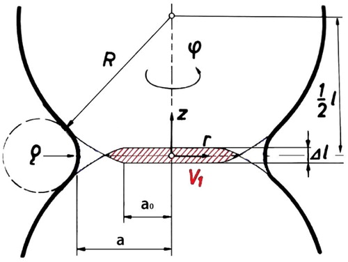
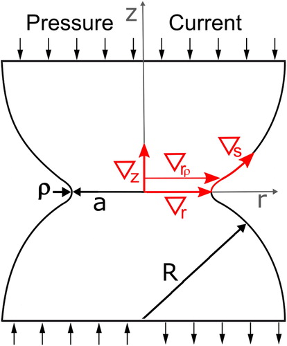
In pressureless sintering, densification is achieved by diffusion of vacancies from the surface of the neck between the sintering particles (ρ c.f. Figure ) to the contact grain boundary where they are annihilated [Citation44]. The reason for the increased vacancy concentration at the neck surface is its curvature, causing a tensile stress – the capillary pressure [Citation45]. This mechanism is thoroughly understood, even though, depending on the boundary conditions used for the mathematical treatment, the calculated flow of vacancies into the grain boundary in the contact between the sintering particles can slightly deviate in different publications [Citation46,Citation47]. The boundary conditions used in the present publication are [Citation46,Citation48,Citation49]:
the normal stress
the neck being free of normal tension without considering the external pressure
Figure 7. Dimension in the two-particle model to calculate densification rates. Densification is expressed as the approach of the particle centres. To reduce their distance l by , the Volume
has to be removed from the contact. As the material is moved to the neck surface, the contact radius grows from
to a.
With the surface tension γ, the vacancy flux per unit area and unit time driven by the surface curvature can be described by:
(8)
(8) In Equation (Equation8
(8)
(8) ) the capillary pressure as the driving force is given by
(9)
(9) For pressure assisted sintering, the compressive force reduces the vacancy concentration along the contact grain boundary, where the external pressure P is transmitted from one particle to the other. Assuming simple cubic packing of the powder particles, the resulting mean compressive stress that acts as an additional driving force besides the surface curvature is given by:
(10)
(10) Thereby the factor 3/2 is introduced as, like for pressureless sintering [Citation47] the diffusion leads to a parabolic stress distribution normal to the grain boundary, with the maximum stress being 3/2 of the mean value.
2.6. Maximal contribution to densification
The densification of a powder compact on the macroscopic scale is equivalent to the approaching centres of the particles described in the two-particle model on the microscopic scale. For the case of uniaxial pressing, with the height of the powder compact h, both values are related by . The densification rate both on the microscopic and the macroscopic scale is then generally given by
(11)
(11) The approach of the particle centres in the microscopic model is achieved by the annihilation of vacancies in the contacts grain boundary. It can be calculated from the volume
removed per unit time, with
(c.f. Figure ). This volume is also given by the flow of vacancies into the grain boundary per unit time, that can be calculated by multiplying
with the volume of an atom, Ω. Setting both volumes equal gives
(12)
(12) and the combination of Equations (Equation11
(11)
(11) ) and (Equation12
(12)
(12) ) yields:
(13)
(13) To compare the theoretical densification rates, the flux of vacancies per unit area and unit time given in Equations (Equation6
(6)
(6) ) to (Equation8
(8)
(8) ) has to be integrated over the area across which this flux is realised. For electromigration and thermomigration, as both the electrical current and the temperature gradient occur along z with z = 0 being both an isotherm as well as an equipotential [Citation50] in the analytical solution,
is used as area. Densification by curvature and pressure-assisted diffusion is driven by the vacancies coming from the neck surface, diffusing directly through the grain boundary as well as through the adjacent lattice. This flux through the grain boundary can be calculated by integrating Equation (Equation8
(8)
(8) ) including the additional driving force of the external pressure at r = a from z = 0 to
, whereby b denominates the Burgers vector, and using the grain boundary diffusion coefficient
. For lattice diffusion, with
, integration is from z = 0 to
while using the lattice diffusion coefficient
. As
, the densification rates can be calculated as given in Table .
Table 3. Formulas to calculate the densification rate for different cases of material transport under the assumption, every atom is moved in a way that it leads to densification. The densification rate for pressure assisted diffusion along the grain boundary differs by a factor of 1.3 to 2 compared to Coble's solution [Citation47], if the simplifications , , and xdx = 2Rdl are used.
Using the material properties given in Table , the resulting densification rates are presented in Figure for sintering a 15 mm diameter µm copper powder compact at
. From the total current of 320 A, approximately 40% flow through the powder compact and 60% through the die [Citation10]. The densification rates for electromigration are in the order of
, for thermomigration in the order of
, and for surface curvature driven diffusion in the order of
to
for lattice and grain boundary diffusion, respectively. The latter ones are increased by a factor of 100 when an external pressure of 17 MPa is applied. In this case, pressure assisted diffusion is by far the most important mechanism, whereby – owing to the low sintering temperature – grain boundary diffusion is more efficient than lattice diffusion.
Figure 8. Densification rates calculated using the experimentally determined current through the powder compact of 128 A, as well as the assumption, the current can be changed to 5000 and 100000 A without varying the sintering temperature. The temperature gradients are obtained from the analytical solution given in Section 2 as . Temperature gradients along z for copper particles with
μm and
are
K/m, 300 K/m, and 115300 K/m, for 128 A, 5000 A, and 100000 A, respectively.
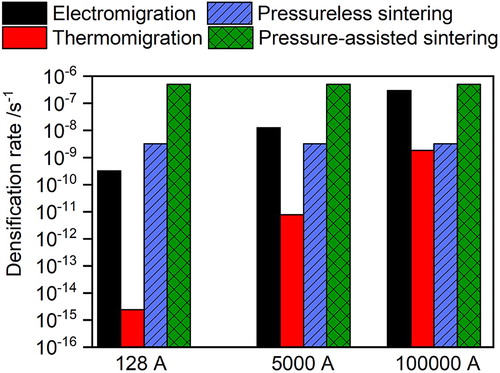
Table 4. Temperature independent material properties or such without information on temperature dependence; steel values for martensitic 1.4034, in brackets for pure α -iron, with index for γ -iron, with index for austenitic 1.4301. Coefficient of diffusion: .
If one could increase the current without changing the sintering temperature, the situation would not fundamentally change even if the current limit of the machine flows through the powder compact only (5000 A). For electromigration, in order to equal the pressure-assisted diffusion, capacitor discharge compaction with 100000 A would be theoretically necessary. In fact, this can lead to the evaporation of the powder compact. Note that the results presented give the maximal densification rates for all mechanisms under the assumption that all of the vacancies are annihilated in the grain boundary and therefore lead to densification. This is not necessarily the case, as in sintering some transport mechanisms lead to neck growth only or even swelling. The qualitative contribution of different paths and mechanisms will be discussed in the following section.
2.7. Discussion of material transport
For the comparison of different driving forces, it is often assumed that every atom is transported in a way that it leads to densification [Citation55], and additional driving forces can be added up. This means every vacancy would originate from the neck surface and would be absorbed in the grain boundary separating two particles. This is not the case here.
In this section, the conditions under which material transport may actually be beneficial for densification will be discussed. Figure shows different paths along which field gradients may occur and which have to be considered. These are (i) along z, i.e. opposite to the direction of the electric current, (ii) along r, either through the contact grain boundary or through the adjacent lattice
, and (iii) along the particles surface, starting from the grain boundary (z = 0) at r = a.
Figure 9. Two-particle model with material flow routes in axial (∇z) and radial direction (through the grain boundary (∇r) and through the adjacent lattice (∇rr)) as well as along the particles surface (∇s).
The quantitative impact on densification of the paths and mechanisms - found to be relevant - will be shown in the next section using temperature and electric field distributions obtained from FE simulations.
2.7.1. Diffusion due to field gradients along
For the path along z, the maximal densification rates due to the electric current and the temperature gradient (with ) have been calculated in Section 2.6. If the electric current transports vacancies along the negative z-direction, the vacancies can be annihilated in the contact grain boundary. This leads to densification, while the atom flux in the opposite direction leads to an increasing particle radius at least in proximity to z = 0. Due to the symmetry of the contact, however, the direct current exits the grain boundary into the next particle without a change in the current strength. Consequently, the same number of vacancies are created at the grain boundary and moved into the next particle as have been annihilated. If electrical resistance and diffusion coefficient do not change, there is no net transport of vacancies and consequently no shrinkage. The latter can be assumed, if the microstructure and temperature profile is mirror-imaged at the contact grain boundary. Furthermore the vacancy flux as described would need effective vacancy sources in one particle and sinks in the other particle. Similarly, even with highest current densities and very long 'process times' in microelectronic conducting paths, at the grain boundaries perpendicular to the current flow, no material transport can be detected. This is also the reason for creating a bamboo-like grain structure to protect conducting paths in microelectronics from electromigration failure [Citation56].
For thermomigration on the other hand, the temperature gradient occurs in the direction of the contact plane from both particle centres. The contribution of thermomigration to densification is therefore twice as high as calculated before. Considering that the heat of transport can attain both positive an negative values, thermomigration could lead to faster as well as slower densification, depending on the material. This does, however, not change its negligible contribution to the material transport as shown in Figure .
2.7.2. Diffusion due to field gradients along
The conclusions drawn above for the gradient of temperature and electric field along the z-axis stay true for diffusion along the particle surface, with the difference that surface diffusion leads to contact growth only and not to shrinkage. For electromigration, there is the possibility of forming undercuts, similar to the movement (but not shrinkage!) of a pore [Citation57]. If the vacancies' heat of transport is positive, thermomigration even leads to a shrinkage of the neck. As the convergence of the particles is not influenced this favours densification in an indirect way, but again with a negligible contribution to material transport as discussed earlier.
2.7.3. Diffusion due to field gradients along and
Gradients in temperature and in electric potential in radial direction act the same way as the gradients of the vacancy concentration created by surface tension or by external pressure known from 'classical' sintering theory. So, they can favour or hinder densification depending on the sign of the effective charge or heat of transport, respectively. has to be considered for grain boundary diffusion and
is given for material transport trough the lattice adjacent to the grain boundary. A potential impact of these gradients can only be assessed from the results of the FE simulations, as z = 0 is both isotherm and equipotential in the analytical solution.
3. Finite-element simulation
Finite-element (FE) simulations have been performed using a fully coupled 3D axisymmetric thermo-electro-mechanical model consisting of two half-spheres in contact, for details, see [Citation20]. Micro-local temperature and electric field distributions were obtained after applying a single current pulse or multiple current pulses of 10 ms followed by a 5 ms pause. From the simulations, temperature, temperature gradient and electric field distribution have been obtained. Exemplary results for temperature and electric field profiles along relevant paths, given in Figure , are presented in Figure .
Figure 10. Temperature, temperature gradient and radial component of the electric field along different paths (c.f. Figure ) from FE simulations using a current of 280 A from model SPS experiments; MPa,
μm copper particles heated with 11500 K/s to
. The relative neck radius is
.
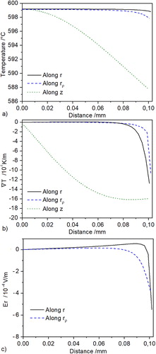
The total temperature difference between z = 0 and z = R, the supertemperature, has been used for a comparison with the analytical solution in Figure . While the mean temperature gradient along z is , the maximum of
occurs at
and is about three times higher than the mean value. Temperature evolution and electric field along the grain boundary show that close to the neck surface the assumption of the grain boundary being both isotherm as well as equipotential is not fully correct.
The maximal temperature gradients along z, r, and ρ as well as the radial component of the electric field are summarised in Table . These results are for the sintering of μm copper particles at
C after 70% of the theoretical density is reached.
Table 5. Temperature gradients , radial component of the electric field and resulting densification rates for m copper powder after heating to C with a total current of 320 A. Values for a relative neck size of in pressing direction. With % of the theoretical density, the current is assumed to flow through 18140 parallel particles.
3.1. Realistic contributions of electromigration and thermomigration to densification
The maximal contributions of electro- and thermomigration to densification have been estimated in Section 2.6. The results show that only for capacitor discharges, current densities large enough to make a significant contribution to diffusion controlled densification mechanisms can be realised. In the latter scenario, however, densification is achieved in milliseconds, and caused by melting of the contacts, whereby the liquid phase fills the pore-space between the particles [Citation33].
After a closer look at the direction of current flow as well as the role of vacancy sources and sinks in Section 2.7, FE simulations have been used to obtain accurate temperature and electric field gradients relevant for densification. Those simulations also give the gradients along the grain boundary that cannot be obtained from analytical calculations. The results are given in Table . Detailed equations used for each mechanism and path are given in Table . Compared to pressure-assisted sintering, all of these mechanisms give only negligible contributions. It has to be noted that even the calculated densification rate for pressure assisted diffusion is smaller than the measured one. We will discuss this in the last part of this series of publications.
Table 6. Equations used to calculate the densification rate with the driving forces obtained from FE simulations given in Table .
The question remains, why electro- and thermomigration are still considered relevant for SPS in many publications. To answer this question, results from other research groups will be reviewed in the following sections.
3.1.1. Electromigration in literature
The vast majority of electromigration literature comes from the field of microelectronics, where failure e.g. due to void formation is investigated. There it is shown that usually changes in the diffusion coefficient caused by microstructural features like a varying grain size are premises for a material flux. These features provide sources and sinks for the vacancies, as otherwise material transport necessarily stops after a – current density dependent – critical gradient in the concentration of vacancies is formed [Citation58]. To favour densification in SPS by moving more vacancies into the contacts grain boundary than removing from it, e.g. the grain size of the particle the current comes from would have to be larger than that of the particle the current enters next. This is not the case. Additionally, current densities in microelectronics are in the range of A/mm
, compared to
A/mm
in SPS. At the same time the duration of the electromigration experiments is hours to days, compared to a couple of minutes in SPS. The temperature is usually below SPS values, ranging from
up to
[Citation59,Citation60]. As a consequence, the principal relevance of this literature for SPS can be seen in providing values for the effective charge.
Experimental and theoretical studies from the area of contact physics found electromigration to be the most efficient mass transport mechanism [Citation61]. This, however, for a current density of A/mm
, at least four orders of magnitude higher than in SPS. If the equations developed in Ref. [Citation61] are applied to SPS conditions from the present publication, they show no relevant influence of electromigration on material transport.
In other model experiments frequently cited in support of the 'spark plasma effect', multi-layers of foils or plates were used to asses the influence of the electric current on phase formation. Growth rates of intermetallic phases or carbides are reported to be accelerated [Citation62–68]. As in these studies the enhanced phase formation was not correlated to the direction of the electric current, electromigration can be excluded as the cause. Other explanations for the enhanced phase formation had to be given, like (local) Joule heating of the contacts [Citation58], faster nucleation of the new phase [Citation63], or an enhanced mobility of defects [Citation66,Citation67,Citation69]. One of few experimental evidences stem from positron annihilation spectroscopy, that revealed a ten fold increased vacancy concentration in Al-Cu lines upon current stressing. However, the current density reached almost A/mm
[Citation70]. Despite this, it has to be noted that the concentration of vacancies is relevant for phase formation by diffusion, but does not affect densification. Densification is only determined by the gradients of the vacancy concentration along the grain boundaries in the particle contacts, which are determined by either the surface curvature and/or the external pressure [Citation71]. Furthermore, some of the experiments have been repeated by the group of Moncheaux using multi-layered foils of Ag-Zn [Citation72]. They show that for current densities up to 10 A/mm
(that could only be realised using copper punches [Citation31]), there is no influence of the electric current on phase formation. They claim that enhanced phase formation has often to be attributed to difficulties in temperature measurement in the contact between the foils. The opinion that electromigration has no influence on the formation of intermetallics is supported by R. Timsit for electric contacts, were the current densities of
A/mm
are similar to SPS (c.f. p. 43 in [Citation12]). The finding that electromigration does not influence material transport under SPS-conditions is also supported by other publications, where the observed faster formation of Cu-Ni solid solutions in experiments using multi-layered foils [Citation73] could not be reproduced in an experiment using a SPS machine for the densification of Cu and Ni powders [Citation74]. Besides the lower current density used there, SPS samples were fully densified long before any current effect on phase formation was observable.
More relevant work on the contribution of electromigration to densification was done by the group of Olevsky [Citation75,Citation76] performing a series of finite-element simulations. They show the dominance of electromigration over surface pressure or even external pressure driven densification for a grain size above μm and low porosity (
%) in SPS of aluminium. A closer look at the process parameters used for the simulations shows: the electrical conductivity of an aluminium compact with 10% porosity [Citation77] and an electric field of 4 V/cm would result in a current density of
to
A/mm
and vaporisation of the metal.
Finally, electromigration accelerated Coble creep was investigated [Citation78]. For a SPS-typical pressure of 10 MPa and a grain size of 10 μm, a current density larger than A/mm
would be necessary for electromigration to make a significant contribution to mass transport, more than 100 times larger than in SPS.
Concluding, it is out of question that electromigration exists and it seems possible to show some contribution to densification in an SPS apparatus by using no or a very low pressure ( MPa) as well as very large particles (
μm) and a non-conductive die. Yet, these cases are not relevant for a reasonable application of SPS to densify especially fine grained materials in a short time utilising the benefits of external pressure application.
3.1.2. Thermomigration in literature
The effect of thermomigration is even smaller than that of electromigration [Citation79]. That is probably the reason for the very limited amount of available research and little knowledge about exact values of the heat of transport , of which sometimes even the sign is unclear [Citation38,Citation80,Citation81].
It is the authors' present believe that the regular mentioning of thermomigration in SPS literature stems from an article by Young and McPherson [Citation55] about sintering in a plasma with a large macroscopic temperature gradient through the sample. These authors compare vacancy flux equations for thermomigration and surface curvature driven diffusion. However, the driving force of a macroscopic temperature gradient in a specimen heated from the outside must not be compared to a gradient in the concentration of vacancies caused by the curvature of the neck surface [Citation82]. Moreover the authors do not take into account any mechanical pressure. Despite that, their result of thermomigration exceeding surface curvature driven diffusion is commonly repeated.
A numerical analysis of the impact of thermomigration on densification was undertaken by the group of Olevsky [Citation83]. They asses its influence in SPS of alumina with a fixed porosity of 30% and conclude that it may even exceed densification by power law creep for temperatures above 1600 K. Even though this article is about a ceramic, it has to be pointed out that in their own experimental work, the samples are fully densified at 1423 K and the high impact of thermomigration is for unrealistic process parameters.
3.2. Impact of the pulsed current on the coefficient of diffusion
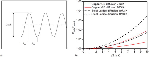
The pulsed current might affect densification in different ways. One is the difference between momentary current and root mean square (RMS) current. The latter is the equivalent steady constant current that produces the same heat as a pulsed current during a certain time interval. Pulsing the current must lead to an increased current amplitude during pulse-on time when keeping the RMS current constant [Citation10,Citation84]. For pulse patterns relevant in SPS, the peak current is % higher than the RMS current. This slight increase cannot alter the findings in the presented work that there is no influence of the electric current on material transport.
Pulsing the current also leads to fluctuations in the temperature, both on a macroscopic and a microscopic scale. This fluctuation caused by repeated Joule heating and the eventual heat loss due to conduction or radiation via the punches or the surface of the die by is schematically depicted in Figure . With the diffusion coefficient being exponentially dependent on temperature, the reduction of D during the sintering at the lower temperature
is less pronounced than its increase during sintering at the higher temperature
. Considering a pulse pattern with equal on and off time,
, to assess the rate of accelerated densification, an effective coefficient of diffusion can be calculated:
(14)
(14) This effective diffusion coefficient divided by D at temperature T is given in Figure for temperature differences up to
K. Even for
K that can be reached during (uncontrolled) heating with about 1000 K/s
(note: not per minute!), diffusion would be accelerated by 1% only. The conclusion that pulsing does not have any effect on the diffusion coefficient and consequently on phase formation or densification is supported by results from other groups [Citation67,Citation84–86].
Figure 11. (a) Schematic representation of fluctuating temperature due to the pulsed current and (b) impact of pulsed temperature on the effective diffusion coefficient.
4. Conclusions
The evolution of the micro-local temperature in a powder particle during pulsed current heating was investigated. After the current starts, initially the particle-particle contacts are heated, but the temperature reaches the centre of the particles in less than one millisecond. After that, an almost constant supertemperature – the temperature difference between contact and centre – is established. The supertemperature lies between 10
K and 1 K, depending on tool setup, material to be sintered, and heating rate. After the sintering temperature is reached, the decreasing current leads to an even smaller supertemperature.
As the 'overheating' of the particle contacts obviously cannot lead to faster densification, the maximal possible contributions of surface curvature and external pressure driven diffusion, electromigration, and thermomigration to densification were investigated. Material transport caused by the external pressure and, for nano-powders, by the surface curvature dominate over thermo- and electromigration by orders of magnitude. This findings from the analytical model presented are backed by finite-element simulations. Also, an analysis of the material flow routes showed that, even for highest current densities, electromigration won't contribute to densification due to the symmetry of material transport to and from the grain boundary in the particle contacts. If high voltages above 10 V, a non or weakly electrical conducting die, low resistance punches, very large particles and preferably a low pressure would be used, thermomigration might possibly enhance densification, or hinder it, depending on the sign of the heat of transport. This is, however, a purely academic consideration. The processing parameters in spark plasma sintering should always be chosen to exploit the very efficient enhancement of densification by external pressure driven diffusion, plastic deformation, and various creep mechanism by using a higher pressure and finer powders.
The influence of pulsing the current on temperature and with this on the diffusion coefficient is minimal for typical pulse patterns, as the RMS current and the actual (peak) current during pulse-on time do not significantly differ. The reason therefore is the limited voltage of the power supply that does not allow pulse patterns larger than . The effect on the coefficient of diffusion and therefore the acceleration of densification is an increase by less then 1%.
Still, densification rates predicted in the present publication are lower than experimentally observed, possibly due to creep deformation. This will be discussed in the third part of this set of papers.
Acknowledgments
This research has been supported by the German Research Foundation (DFG) under the grants KI506/20-2 and WA2323/10-2.
Disclosure statement
No potential conflict of interest was reported by the author(s).
Notes on contributors
Johannes Trapp received his Ph.D. in Engineering from Technische Universität Dresden in 2017. He now works in the field of additive manufacturing focusing on selective electron beam melting (EBM) at the Dresden Lab of Fraunhofer Institute of Manufacturing and Advanced Materials (IFAM). He also works on powder metallurgical processes, spark plasma sintering, capacitor discharge compaction, joining techniques, high energy milling and self-propagating high-temperature synthesis.
Artem Semenov got his doctorate degree from the St. Petersburg Polytechnic University in 1996, specialising in nonlinear continuum mechanics. He now works at the Department of Mechanics of Multifunctional Structures (Technische Universität Dresden) and as head of the chair of Strength of Materials and deputy director of the High school of Mechanics and Сontrol processes in the Institute of Applied Mathematics and Mechanics (Peter the Great St. Petersburg Polytechnic University). His research interests include theory of plasticity, fracture and damage mechanics, ferroelectricity/ferroelasticity, and computational mechanics.
Oliver Eberhardt is a Ph.D. student at the chair for Mechanics of Multifunctional Structures at the Institute of Solid Mechanics at TU Dresden. His thesis focusses on the behavior of nanoscale materials adressed by a molecular mechanics approach. His research comprises the behavior of nanoscale materials, the numerical solution of multi-field problems and more recently wearable robotics. He has been a reviewer for multiple scientific journals.
Michael Nöthe received his Ph.D. in natural sciences from RWTH Aachen University in 2000. Starting in 2001 he has been working at the Technische Universität Dresden on fundamental investigations of the cooperative material transport during sintering of metal powders using high resolution computed tomography combined with computed image analysis. Since 2014 he is conducting experimental investigations of the fundamentals of spark plasma sintering.
Thomas Wallmersperger is a full professor for Mechanics of Multifunctional Structures at the Institute of Solid Mechanics and Associate Dean of the Faculty of Mechanical Science and Engineering at TU Dresden. His research topics comprise coupled multi-field problems, material modelling, micromechanics, adaptive materials and smart structures, discretisation and numerical modelling. He completed his Ph.D. thesis in 2003 and his habilitation in 2010 in Stuttgart, Germany. Currently he is Associate Editor of the Journal of Intelligent Material Systems and Structures as well as Member of the Editorial Board of Acta Mechanica and of Micromachines.
Bernd Kieback works at Technische Universität Dresden, Institute of Materials Science. From 1993 until 2019 he held the chair ‘Powder Metallurgy, Sintered and Composite Materials’. From 1992 until 2019 he also worked at Fraunhofer Institute of Manufacturing and Advanced Materials (IFAM) as director of the Dresden Lab. The activities in both organisations are oriented on processes of powder metallurgy, sintered materials and metal matrix composites.
Additional information
Funding
References
- Castro R, van Benthem K. Sintering: mechanisms of convention nanodensification and field assisted processes. Berlin Heidelberg: Springer; 2013.
- Guillon O, Gonzalez-Julian J, Dargatz B, et al. Field-assisted sintering technology/spark plasma sintering: mechanisms, materials, and technology developments. Adv Eng Mater. 2014;16(7):830–849.
- Orrù R, Licheri R, Locci AM, Consolidation/synthesis of materials by electric current activated/assisted sintering. Mater Sci Eng: R: Rep. 2009;63(4-6):127–287.
- Saunders T, Grasso S, Reece MJ. Plasma formation during electric discharge (50 V) through conductive powder compacts. J Eur Ceram Soc. 2014;35(3):871–877.
- Hulbert DM, Anders A, Dudina DV, et al. The absence of plasma in spark plasma sintering. J Appl Phys. 2008;104(3):33305–33307.
- Hulbert DM, Anders A, Andersson J, et al. A discussion on the absence of plasma in spark plasma sintering. Scr Mater. 2009;60(10):835–838.
- Yanagisawa O, Kuramoto H, Matsugi K, et al. Observation of particle behavior in copper powder compact during pulsed electric discharge. Mater Sci Eng A. 2003;350(1-2):184–189.
- Suárez M, Fernández A, Menéndez JL, et al. Challenges and opportunities for spark plasma sintering: a key technology for a new generation of materials. In Burcu Ertuğ, editor, Sintering applications, London: IntechOpen; 2013. p. 319–342.
- Ragulya AV. Fundamentals of spark plasma sintering. Ref Module Mater Sci Mater Eng. 2016: 1–5.
- Trapp J, Kieback B. Fundamental principles of spark plasma sintering of metals: part i– joule heating controlled by the evolution of powder resistivity and local current densities. Powder Metall. 2019;62(5):297–306.
- Holm R, Holm E. Electric contacts: theory and application. Berlin Heidelberg: Springer; 1967.
- Slade PG. Electrical contacts: principles and applications. Boca Raton:Taylor & Francis Group; 2014.
- Semenov AS, Trapp J, Nöthe M, et al. Experimental and numerical analysis of the initial stage of field-assisted sintering of metals. J Mater Sci. 2017;52:1486–1500.
- McWilliams B, Zavaliangos A. Multi-phenomena simulation of electric field assisted sintering. J Mater Sci. 2008;43(14):5031–5035.
- Greenwood J, Harris J. Electrical conduction in solids. III. The contact of iron surfaces. Proc R Soc A: Math Phys Eng Sci. 1960;257(1288):83–97.
- Herger P. Elektrische Leitfähigkeit von kugelförmigem Kupferpulver unter Druck. Arch Elektrotech. 1977;59(5):275–277.
- Kohler M, Zielasek G. Der zeitliche Temperaturverlauf in elektrischen Kontakten. Abhandlungen der Braunschweigischen Wissenschaftlichen Gesellschaft. 1952;4:117–126.
- Carslaw HS, Jaeger JC. Conduction of heat in solids. Oxford:Oxford University Press; 1959.
- Trapp J, Kieback B. Temperature distribution in metallic powder particles during initial stage of field-activated sintering. J Am Ceram Soc. 2015;98(11):3547–3552.
- Semenov AS, Trapp J, Nöthe M, et al. Thermo-electro-mechanical modeling, simulation and experiments of field-assisted sintering. J Mater Sci. 2019;54(15):10764–10783.
- Simmons JG. Generalized formula for the electric tunnel effect between similar electrodes separated by a thin insulating film. J Appl Phys. 1963;34(6):1793–1803.
- Zinoviev VE. Thermo-physical properties of metals at high temperatures. Moscow: Metalurgia; 1989.
- Chu TK, Ho CY. Electrical resistivity and thermal conductivity of nine selected AISI stainless steels. Technical report, Defense technical information center, 1977.
- Song X, Liu X, Zhang J. Neck formation and self-adjusting mechanism of neck growth of conducting powders in spark plasma sintering. J Am Cera Soc. 2006;89(2):494–500.
- Holland TB, Anselmi-Tamburini U, Quach DV, et al. Effects of local Joule heating during the field assisted sintering of ionic ceramics. J Eur Ceram Soc. 2012;32(14):3667–3674.
- Kuz'mov AV, Olevsky EA, Aleksandrova EV. Effect of micrononuniform heating of powder in field-Assisted sintering on shrinkage kinetics. Powder Metallurgy Metal Ceram. 2013;51(11):657–665.
- Zhao J, Wang GX, Dong Y, et al. Multiscale modeling of localized resistive heating in nanocrystalline metals subjected to electropulsing. J Appl Phys. 2017;122(8):085101.
- Bulat LP, Nefedova IA, Pshenay-Severin DA. Targeted Use of SPS Method for Improvement of Thermoelectrics. In Pietro Vincenzini Advances in Science and Technology: 6th Forum on New Materials - Part A, Vol. 93, Trans Tech Publ. Baech: Switzerland; p. 168–173. 2014.
- Mani MK, Viola G, Hall JP, et a. Observation of curie transition during spark plasma sintering of ferromagnetic materials. J Magn Magn Mater. 2015;382:202–205.
- Collard C, Trzaska Z, Durand L, et al. Theoretical and experimental investigations of local overheating at particle contacts in spark plasma sintering. Powder Technol. 2017;321:458–470.
- Trzaska Z, Collard C, Durand L, et al. Spark plasma sintering microscopic mechanisms of metallic systems: experiments and simulations. J Am Cera Soc. 2018;102:1–8.
- Rogachev AS, Vadchenko SG, Kudryashov VA, et al. Direct observation of processes at particle-to-particle contacts during electric pulse consolidation of a titanium powder. Doklady Physical Chemistry. 2019;488(2):151–153.
- Schütte P, Garcia J, Theisen W. Electro discharge sintering as a process for rapid compaction in pm-technology. pages 91–99. Proceeding Nr. 3, EPMA Euro PM2009, Copenhagen, Denmark (12-14 October 2009), 2009.
- Leich L, Röttger A, Theisen W, et al. Densification of nanocrystalline ndfeb magnets processed by electro-discharge sintering – microstructure, magnetic, and mechanical properties. J Magn Magn Mater. 2018;460:454–460.
- Fais A. A faster FAST: electro-sinter-forging. Metal Powder Rep. 2018;73:80–86.
- Lagos MA, Agote I, Schubert T, et al. Development of electric resistance sintering process for the fabrication of hard metals: processing, microstructure and mechanical properties. Int J Refractory Metals Hard Mater. 2017;66:88–94.
- Manière C, Lee G, Olevsky EA. All-materials-inclusive flash spark plasma sintering. Sci Rep. 2017;7:1–8.
- Huntington HB. Electromigration in metals. Diffusion in solids: recent developments, 303–352, 1975.
- Adda Y, Philibert J. La diffusion dans les solides. Paris: Presses Universitaires De France; 1966.
- Wirtz K. Zur kinetischen Theorie der Thermodiffusion im Kristallgitter. Phy Z. 1943;44(11):221–231.
- Wever H. Thermodiffusion in binären metallischen Mischphasen. Z Naturforsch A. 1963;18(11):1215–1224.
- Fiks VB. The thermal-diffusion mechanism in liquids. Soviet Phys -- Solid State. 1961;3(3):994–997.
- Gillan MJ. Diffusion in a Temperature Gradient. In Mass Transport in Solids, Boston, MA:Springer US; 1983, p. 227–250.
- Schatt W. Sintervorgänge / Grundlagen. Düsseldorf: VDI Verlag; 1992.
- Geguzin JE. Physik des Sinterns. Lepzig: Deutscher Verlag für Grundstoffindustrie; 1973.
- Johnson DL, Clarke TM. Grain boundary and volume diffusion in the sintering of silver. Acta Metallurgica. 1964;12(10):1173–1179.
- Coble RL. Diffusion models for hot pressing with surface energy and pressure effects as driving forces. J Appl Phys. 1970;41(12):4798–4807.
- Lányi P. Strukturelle Aktivität und Verdichtungskinetik im Frühstadium des Sinterprozesses. PhD thesis, Akademie der Wissenschaften der DDR, 1980.
- Staab T. Positronenlebensdauerspektroskopieuntersuchungen zum Sinterprozess in Metallpulverpresslingen: der Einfluss von Gefüge und Mikrostruktur auf den Materialtransport. PhD thesis, Martin-Luther-Universität Halle-Wittenberg, 1997.
- Kohlrausch F. Über den stationären Temperaturzustand eines elektrisch geheizten Leiters. Ann Phys. 1900;306(1):132–158.
- Brandes EA, Brook GB. Smithells metals reference book. Oxford, Burlington: Elsevier Butterworth-Heinemann; 1992.
- Deutsche Edelstahlwerke GmbH. 1.4034 -- Nichtrostender martensitischer Chrom-Stahl, 2007 .
- Deutsche Edelstahlwerke GmbH. 1.4301 -- Nichtrostender austenitischer Chrom-Nickel-Stahl, Revisions-Nr. 1.4301/1, 2008 .
- Frost HJ, Ashby MF. Deformation-mechanism maps: the plasticity and creep of metals and ceramics. Oxford [Oxfordshire], New York: Pergamon Press; 1982.
- Young RM, McPherson R. Temperature-gradient-driven diffusion in rapid-Rate sintering. J Am Ceramic Soc. 1989;72(6):1080–1081.
- Kwok T. Effect of metal line geometry on electromigration lifetime in al-cu submicron interconnects. In 26th Annual Proceedings Reliability Physics Symposium, p 185–191, 1988.
- Fridline DR, Bower AF. Influence of anisotropic surface diffusivity on electromigration induced void migration and evolution. J Appl Phys. 1999;85(6):3168–3174.
- Orchard HT, Greer AL. Electromigration effects on compound growth at interfaces. Appl Phys Lett. 2005;86:231906.
- Pierce DG, Brusius PG. Electromigration: A review. Microelectron Reliab. 1997;37:1053–1072.
- Ceric H, Selberherr S. Electromigration in submicron interconnect features of integrated circuits. Mater Sci Eng R: Rep. 2011;71(5-6):53–86.
- Runde M, Kongsjorden H, Kulsetås J, et al. Detection of a-spots in aluminum contacts. IEEE Trans Compon, Hybrids, Manuf Technol. 1986;9(1):77–85.
- Liu WC, Chen SW, Chen CM. The Al/Ni interfacial reactions under the influence of electric current. J Electronic Mater. 1998;27(1):L6–L9.
- Bertolino N, Garay J, Anselmi-Tamburini U, et al. Electromigration effects in Al-Au multilayers. Scr Mater. 2001;44:737–742.
- Garay JE, Anselmi-Tamburini U, Munir ZA. Enhanced growth of intermetallic phases in the Ni-Ti system by current effects. Acta Mater. 2003;51(15):4487–4495.
- Friedman JR, Garay JE, Anselmi-Tamburini U, et al. Modified interfacial reactions in Ag-Zn multilayers under the influence of high DC currents. Intermetallics. 2004;12(6):589–597.
- Kondo T, Yasuhara M, Kuramoto T, et al. Effect of pulsed DC current on atomic diffusion of Nb-C diffusion couple. Mater Sci. 2008;43(19):6400–6405.
- Kondo T, Kuramoto T, Kodera Y, et al. Enhanced growth of Mo2C formed in Mo-C diffusion couple by pulsed DC current. J Japan Soc Powder Powder Metall. 2008;55(9):643–650.
- Kondo T, Kuramoto T, Kodera Y, et al. Influence of pulsed DC current and electric field on growth of carbide ceramics during spark plasma sintering. J Ceramic Soc Japan. 2008;116(1359):1187–1192.
- Garay JE, Glade SC, Anselmi-Tamburini U, et al. Electric current enhanced defect mobility in NiTi intermetallics. Appl Phys Lett. 2004;85:573.
- Asoka-Kumar P, OBrien K, Lynn KG, et al. Detection of current-induced vacancies in thin aluminum-copper lines using positrons. Appl Phys Lett. 1996;68(3):406–408.
- Skorokhod VV. Investigation of densification kinetics during sintering. Poroshkovaya Metallurgiya. 1961;3:31.
- Trzaska Z, Monchoux JP. Electromigration experiments by spark plasma sintering in the silver-zinc system. J Alloys Compd. 2015;635:142–149.
- Zhao J, Garay JE, Anselmi-Tamburini U, et al. Directional electromigration-enhanced interdiffususion in the Cu – Ni system. J Appl Phys. 2007;102: 114902.
- Rudinsky S, Brochu M. Interdiffusion between copper and nickel powders and sintering map development during spark plasma sintering. Scr Mater. 2015;100:74–77.
- Olevsky EA, Froyen L. Constitutive modeling of spark-plasma sintering of conductive materials. Scr Mater. 2006;55(12):1175–1178.
- Olevsky EA, Kandukuri S, Froyen L. Analysis of mechanisms of spark-Plasma sintering. Key Eng. Mater.. 2008;368–372:1580–1584.
- Montes JM, Cuevas FG, Cintas J, et al. Electrical conductivity of metal powders under pressure. Appl Phys A: Mater Sci Process. 2011;105(4):935–947.
- Li ZH, Dong Y, Li S, et al. Electromigration-induced coble creep in polycrystalline materials. Appl Phys Lett. 2007;91:191–902.
- Runde M. Mass transport in stationary contact points. Components, Hybrids, Manufact Technol, IEEE Trans on. 1987;10(1):89–99.
- Oriani RA. Thermomigration in solid metals. J Phys Chem Solids. 1969;30:339–351.
- Wever H. Elektro- und Thermotransport in Metallen. Leipzig: Barth; 1973.
- Johnson DL. Comment on: Temperature-gradient-driven diffusion in rapid-rate sintering. J Am Ceramic Soc. 1990;73(8):2576–2578.
- Olevsky EA, Froyen L. Impact of thermal diffusion on densification during SPS. J Am Ceramic Soc. 2009;92:S122–S132.
- Chen W, Anselmi-Tamburini U, Garay JE, et al. Fundamental investigations on the spark plasma sintering/synthesis process: I. Effect of dc pulsing on reactivity. Mater Sci Eng A. 2005;394:132–138.
- Xie G, Ohashi O, Chiba K, et al. Frequency effect on pulse electric current sintering process of pure aluminum powder. Mater Sci Eng A. 2003;359(1-2):384–390.
- Anselmi-Tamburini U, Gennari S, Garay JE, et al. Fundamental investigations on the spark plasma sintering/synthesis process II. Modeling of current and temperature distributions. Mater Sci Eng A. 2005;394:139–148.