
ABSTRACT
In this work, the results of a detailed art technological investigation of the icon Last Supper from the Russian Memorial Church in Leipzig (Germany) are presented. The icons of the iconostasis of the church were made in the workshop of N.S. Emelyanov in Moscow in 1912. The investigation showed that the painter in principle technologically adhered to the traditional way of making icons. The panel is made of boards of lime wood with two crossbars on the reverse. The paint was applied to a chalk ground over a textile layer. The traditional iconographer’s palette was expanded by a few contemporary pigments. The binding agent is classic egg tempera. Originally, the layers of paint had an oil varnish (olifa). The main aim of the project VirtEx, introduced in this paper, is to expand existing methods with numerical material and structural models to be able to predict quantitatively the behaviour of wooden artefacts under loads due to climate changes as well as mechanical loads. The detailed art technological investigation provides the required data for the computer models. The numerical data can then be validated with technologically exact copies and replicas. In the introduction to the article, the current state of research on icon painting techniques is also outlined.
Introduction
The main topic of this article is the artistic technique of the icon Last Supper in the Russian Memorial Church in Leipzig. Furthermore, the larger project in which this investigation takes place, as well as the historical development of art technology of Russian icons, are presented. Virtual Experiments for Artwork (VirtEx) is an international and inter-disciplinary project carried out at Dresden University of Fine Arts (HfBK), Institut für Holztechnologie Dresden (IHD), and Institute for Structural Analysis at Technische Universität Dresden (ISD) together with further experts and institutions in the fields of art history, art technology, restoration, and diagnostics and monitoring.
The main project goal is to develop an objective, numerical decision-making tool for conservation and restoration. On the one hand, the tool will enable the careful restoration of wooden objects of cultural heritage. On the other hand, there is the intention to protect artwork preventively and to define or to deal with ambient climate conditions. The idea is to evaluate the effect of different measures on the wooden object for given load or climate conditions by virtual experiments on ‘digital twins'. The evaluation is not limited to visual surface criteria but will give insight into the inner structural load-bearing behaviour. In comparison to other non-destructive monitoring techniques [e.g. X-ray (Stratis et al. Citation2014), acoustic emission (Łukomski et al. Citation2017)], this method is not limited to utilising monitored results but can be used in a preventive manner.
Many artworks are at least mounted on a wooden load-bearing structure or are made primarily of wood. Several challenges in the numerical simulation of wooden artefacts can be identified. Wood has in common with other natural materials that it is sensitive to environmental conditions and long-term mechanical loading. Moreover, wood is anisotropic, i.e. all material properties show a distinct dependency on the material direction (radial, tangential, and longitudinal) (Niemz and Sonderegger Citation2017). Wood is hygro-expansive with changing moisture content. Long-term loading can lead to irreversible creep deformation. Structural defects such as knots, cracks, biological decay, and insect infestations lead to partial weakening. The effective structural and load-bearing behaviour, as well as the load-bearing capacity until damage, are generally not directly observable externally.
For panel paintings, icons, and similar objects, damage to the paint layers must be prevented. Damage can occur inside the ground and paint layers as brittle cracks due to tension or shear, or between the support structure and these layers as interfacial cracks due to shear, which might lead to kinking of these layers under re-compression (Nicolaus and Westphal Citation1999).
Generally, climate changes can cause irreversible damage to wooden artworks like panel paintings. These impairments are difficult to detect and evaluate directly by conventional empirical methods. Climate data are measurable and predictable to a certain extent. But often, the climate cannot be adjusted easily and sustainably in situ. It is state of the art to use empirically determined environmental ranges in which the artwork will not be damaged (IIC Citation2014). The boundaries are based on experience and literature values, which are partially still under discussion.
Within the last decade, different research projects have dealt with risk assessment of wooden artworks and climate control scientifically (Michalski Citation2009; Ashley-Smith, Burmester, and Eibl Citation2013; Duin and Kos Citation2014). Basic research on moisture influence on panel paintings has been carried out at several institutions (Mecklenburg, Tumosa, and Erhardt Citation1998; Hagan, Quasney, and Mecklenburg Citation2004; Bratasz Citation2013). However, realistic predictions of the impact of climate changes on panel paintings and other wooden artworks remain limited up to now. To determine critical strains for the paint layer in the support, Kupczak et al. (Citation2018) presented an online tool to approximate strains in panel paintings dependent on the panel thickness and the climate changes. As it is a rather one-dimensional approach, this simplified tool is not able to yield further information on the overall structural performance of an object such as ‘wash board' (also ‘flying board’) effects, or interactions with support constructions. Both effects are present in the case of the icon investigated in this study. A numerical model and parameter study to analyse the hygro-mechanical interaction between support constructions and ground and paint layers in case of damage are available (Bosco, Suiker, and Fleck Citation2020, Citation2021).
In those cases where the structure is more complex or more accurate results are needed, the finite element method (FEM) can be applied. In order to predict the structural behaviour of the object, the solution is to apply a theoretical, numerical, virtual model of the structure close to reality. The better the input data, i.e. the information on material characteristics and multi-physically coupled material behaviour, the more accurate are the predictions of changes and damage due to climate changes, high mechanical loads, or creep. With the help of FEM, great progress in the description of material characteristics, structural components, and processes in diverse application ranges has been achieved in the recent decade. Our achievements accompanied by more detailed reviews are presented elsewhere (Konopka, Gebhardt, and Kaliske Citation2017; Konopka and Kaliske Citation2018).
Recently, some further experimental and numerical studies in the framework of FEM have been carried out to investigate these aspects in detail. Cracking in historical oak wooden cabinets under indoor climate conditions is predicted using analytical and numerical modelling (Luimes et al. Citation2018; Luimes and Suiker Citation2021). The damage behaviour of the ground and paint layers, i.e. inside these layers and interfacial cracks, is considered by cohesive material formulations (Tantideeravit et al. Citation2013; Wood et al. Citation2018).
The main goal of the VirtEx project is to further develop this digital, universal, economical method towards a practical application serving as an analysis tool for artworks and to evaluate wood properties as well as the interaction between the wooden structure and the ground and paint layers of paintings. FEM applied to artworks can enable predictions on possible or probable damage scenarios and how to react before damage occurs. Appropriate environmental ranges can be defined by virtual experiments for a unique artwork at unique local loadings. In contrast, remediating any actually occurring damage would be much costlier. Furthermore, unnecessarily high cost and environmentally harmful ‘over optimized' and complex air-conditioning can be avoided if more detailed and accurate predictions are available ().
Figure 1. Virtual experiments for an objective decision-making tool for conservation and restoration.
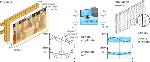
The starting point of this holistic experimental approach is the real artwork. Data on art techniques and materials are prerequisite for understanding mechanical and physical material properties, which allow extraction of the parameters for the numerical material and structural models. Based on historic techniques, an exact copy of a historical painting on a wooden support is produced as precisely as possible to provide data for the modelling as well as to validate the numerical simulations carried out with the model. Together with information on the loading, the virtual experiments based on these models will finally lead back to the artwork, e.g. in terms of simulated deformations or damage potential provoked by a real or hypothetical climate scenario. This straightforward approach is accompanied by experiments on the structural scale to validate the predictive capabilities of the models. In long-term experiments, the deformation and the hygric load are measured photogrammetrically and by sensors inside and outside the structure. A knowledge of artistic techniques and materials gained in this project is necessary for the development of test specimens, too. The exact parameters of these replicas and their climate loadings can be used as input data for the numerical simulation. After successful validation, virtual experiments based on these numerical models of the artwork at different loading cases and climates will help to identify objectively based restoration and conservation measures.
Icons are a class of wooden artwork of almost two-dimensional panel construction. The thick panels (ca. 4 cm), however, cannot be simplified as a two-dimensional structure. The icon Last Supper of the Russian Memorial Church at Leipzig was chosen as the original artwork serving as a reference in this project. Results of the art technological examination as well as its history, including former restoration campaigns, are given below.
Specifically, the investigation of the original icon presented here is aimed at eliciting the following characteristics: type of wood, wood density, wood moisture content, position of the annual rings of the boards, quality of the bond lines, coating materials, thickness of the layers, and application process.
State of scientific knowledge of icon technology
The scientific investigation on the technique of Russian icons has its own history. Since the field of art history in the Western world has not been as focused on icons as has the research in Eastern Europe, a short introduction to this topic follows. In recent times, many technological examinations of icons have been published (e.g. Sandu et al. Citation2009; Stratis et al. Citation2014; Christache et al. Citation2015). However, investigations of early twentieth century icons are still rare. The reason for this lack of interest might be the fact that these icons are simply too young to gain interest. Only lately has this attitude started to change. But still there are huge gaps in technological knowledge about younger icons. With the technological examination of the Leipzig icon Last Supper, we can provide more details about the art technology of icons of that time.
Since analytical results always require an interpretation, the context of the object examined is of interest. It is therefore worth taking a closer look at the history of art technology of icons. Since the second half of the nineteenth century, Russian society's interest in the ancient Russian art of icon painting had begun to grow noticeably. This can be attributed to the trend to remember one's own cultural roots that took place during this period. Icons were no longer seen merely as cult objects but as works of art and were increasingly collected and restored. During these restorations, the original artwork was revealed when layers of overpainting and darkened drying oil were removed. This fuelled the already existing interest even more and the study of Russian icon painting techniques quickly gained popularity.
The first restorers were themselves icon painters and were well versed in the techniques of icon painting, such as N.S. Emelyanov, the author of the icon discussed in this paper. Nevertheless, the primary research was aimed at systematizing knowledge about icons. It was often focused on dating historic artworks and determining the artistic centres of origin. During this period, the foundation was laid for stylistic analysis of historic works of art based on the materials used. In the earliest publications, observations regarding painting techniques were only casually mentioned and rather hidden amongst other topics more pertinent at the time (Aggeev Citation1886; Guryanov Citation1906).
In the 1920s, despite the fact that the leadership of the Soviet Union had no interest in religious paintings, questions regarding iconographic techniques once again became of interest. With the development of photography and its potential, the chance appeared of uncovering artwork layer by layer while creating detailed photographic records of each layer for further research. At this time, the techniques used in early icons were primarily studied in the restoration departments of renowned museums where numerous icons were sent following the closure of monasteries and churches. The necessity of preserving historic pieces and employing more gentle restoration methods began to be acutely felt. It became obvious that oversight was needed by an agency responsible for transferring the uncovering of icons into the academic sphere. In 1918, on the initiative of I.E. Grabar, the oldest state restoration organization in Russia was established in Moscow: The All Russian Commission for the Preservation and Uncovering of Old Russian Art. In 1924, it was reorganized as the Central State Conservation Workshops. The legal successor of this organization is currently the I.E. Grabar All Russian Scientific Art Restoration Centre. Petersburg had its own school of restoration, and, in 1919, the Institute of Archaeological Technology was founded. The objectives of the latter included technical art research as well as giving recommendations on the selection of solvents and creating a methodology for uncovering and preserving historic icons. For this purpose, chemical laboratories were established at both conservation centres. In 1919, I.E. Grabar attempted to take X-ray images of icons for the purpose of further study. The first Russian specialists in this field were S.A. Toporov in Petersburg and N.T. Tikhonov in Moscow. In their work, they drew on the experience of the museums of Europe. The study of icons also took place outside of Russia (Durnovo Citation1926; Schweinfurth Citation1930; Shchavinsky Citation1935).
The second stage of this close attention to iconographic techniques began in the post-war period. Overall, this was linked to the need to restore artwork, including icons that had been damaged during the war. In Moscow in 1957, the All Russian Central Scientific Research Laboratory was founded for the conservation and restoration of museum objects. The study of paintings began to develop as a separate scientific discipline, with research projects dedicated to the study of paintings and iconography appearing in the Soviet Union and abroad (e.g. Onasch Citation1961, 1968). In addition to the practical conservation of historic artworks, a comprehensive integrated study of their material composition was undertaken: conservation materials and techniques for preserving artworks were developed using laboratory studies of pigments, studies using UV and IR radiation, studies in monochromatic light, and spectrophotometry. The results of the scientific efforts of these institutions resulted in a few publications and many internal documents, and in methodical recommendations used for teaching art conservation and in practice within conservation departments of museums. One of the first academic publications on art technique of Russian icons in the Soviet Union was the dissertation of V.V. Filatov (Citation1961). Sources for technical and technological studies in the Soviet Union included the findings of Y.I. Grenberg, later published as a series of articles (Grenberg Citation1971–1975, Citation1976). X-radiography likewise became a standard tool for art researchers.
The role of icons as collectors’ items meant that criminals also began to take an interest in this field. The knowledge gained from the investigation of icons was used in the creation of copies and forgeries. In order to establish authenticity and put a stop to fraud, technological studies conducted by scientists once again came into play. The leading museums of Russia established departments for the study of iconographic techniques, chemical laboratories, and internal evaluation departments. These systematic research efforts enriched the existing knowledge of historic icon techniques with new discoveries, and stylistic differentiation between icons began to be technologically substantiated (Yakovleva Citation1987; Naumova Citation2018).
The icon Last Supper is part of the iconostasis of the Russian Memorial Church in Leipzig, created in 1912–1913. It is the central icon of the festal row depicting the last supper of Jesus and his disciples ( and ).
Figure 2. View of the lower part of the iconostasis of the Russian Memorial Church Leipzig; the icon Last Supper is located directly above the Tsar-door.
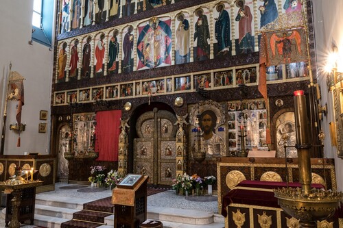
Figure 3. Icon Last Supper (149 × 66.5 cm) by N.S. Emelyanov.
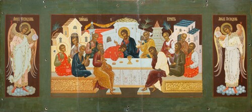
This icon was painted in the workshop of Moscow iconographer Nikolay Sergeyevich Emelyanov (1879 – after 1917). He belonged to the circle of the first restorers independently uncovering medieval icons. He undoubtedly saw the icon Holy Trinity by Andrey Rublev, which V.P. Guryanov stripped of later overpaintings in 1904–1905 (Guryanov Citation1906). According to its style, the icon from Leipzig was painted under the impression and reinterpretation of the historic works of the Novgorod, Moscow, and Pskov schools of iconography of the fifteenth to the early sixteenth centuries.
Nikolay Emelyanov was born into a poor family, in the village of Chorikova (Tarutinskaya volost, Borovsky uyezd) of the Kaluga governorate. In the 1890s, he came to Moscow to find work. The talented young iconographer joined a restoration brigade tasked with various restoration projects in the churches of Moscow and learned the techniques of conservation through hands-on experience. Over time, he was engaged in major projects as an iconographer capable of painting icons in the ancient style. By the 1910s, he was working on major state commissions, including those of the royal family. In Moscow, he led a workshop, which, according to a list in his workshop books, simultaneously worked on the iconostasis for the memorial church in Leipzig, fulfilled large-scale orders for the adornment of the St Theodore Cathedral in Saint Petersburg built in honour of the 300th anniversary of the Romanov dynasty, as well as the St Theodore Cathedral in Tsarskoye Selo at the residence of Tsar Nicholas II (Derzhavina Citation2015, 48). As a result, he became the last iconographer of the Romanov royal family. Signed works by Nikolay Emelyanov are found in museums, churches, and private collections.
Methods
The icon was examined under visible light as well as ultraviolet light. Infrared photography was carried out by Gisbert Sacher (Focus Leipzig GmbH) using a modified SLR camera (Nikon D800, sensitive up to about 1100 nm, with a UV-Nikkor 4.5–105 mm lens and a Heliopan RG715 filter which transmits above 715 nm).
On small wood samples, microscopic identification of the species was carried out. For wood moisture measurements, the electrical resistance method was used. A Hydromette RTU 600 meter (Gann) was used. To validate the measurements, the oven-drying method was used on a small piece of the same wood found on the back of the Leipzig iconostasis. A second measurement was carried out using a different meter, GMH 3800 (Greisinger).
The average wood density was measured by weighing the whole icon.
Computer tomography (CT) (built for scanning humans, System Symbia Intevo 2 (SPECT/CT) from Siemens, resolution 1.4 mm for all directions) was used to examine the construction. X-ray parameters were set according to Fuhrman et al. (Citation2019).
For pigment identification with polarized light microscopy (PLM), samples of the paint layer were treated with methanol to remove the binder and, subsequently, embedded in a thermoplastic resin (Cargille Meltmount, n = 1.662). A Jenavert (Carl Zeiss Jena) and a Leitz–Wetzlar optical microscope were used.
For preparation of cross-sections, the paint samples were embedded in light curing acrylic resin (Technovit 2000LC) or polyester resin (Vosschemie GTS) and polished with abrasive paper and abrasive cloth (Micro-Mesh®). Light microscopy was performed using a Leica DM6000 (incident light from a 100W halogen bulb) with objectives 5×–50×. UV fluorescence was achieved with an HBO-100 mercury vapour lamp and a Leica filter block ‘A'. Histochemical staining of cross-sections was carried out with a fluorescent reactive dye specific to protein (Sypro ruby) (Sandu et al. Citation2012).
Portable X-ray fluorescence (pXRF) was carried out with a hand-held Thermo Niton XL3 air, equipped with an Ag anode and a SDD-‘GOLDD' detector. Measuring parameters were 50 kV, 200 μA (2 W). Filters and measuring time were standard (10 s), low (10 s), high (10 s), light (30 s), measuring spot diameter was 3 mm. Evaluation of data was carried out with the instrument’s software; the chosen routine was ‘minerals with Cu/Zn’ (Analyticon).
Fourier transform infrared spectroscopy (FTIR) was performed with a Bruker Hyperion 2000 attached to a Tensor 27. The samples were manually prepared in a diamond anvil cell (HPDO) and measured in transmission using a 20x IR objective. Alternatively, selected areas of cross-sections were measured in attenuated total reflection (ATR) mode, using a Bruker ATR objective (25x) equipped with a germanium crystal. For FTIR spectroscopy in reflection mode (R-FTIR) on the surface of the painting, a Bruker ALPHA FTIR spectrometer equipped with reflection module was used, with measuring spot diameter of 6 mm.
Raman microspectroscopy (RS) was performed on cross-sections previously prepared for microscopic investigations. A dispersive Horiba Jobin Yvon XPlora Raman microscope was used, equipped with objectives 10x, 50x, and 100x and a charge-coupled device (CCD) detector. A diode pumped solid-state laser (532 nm, P ≤ 50 mW) or a continuous wave diode laser (785 nm, P ≤ 12 mW) were applied. Output laser powers were adjusted to the Raman response of the different samples. A holographic grating of 1200 rulings/mm provided a dispersion of 14.2 cm−1/mm (532 nm) or 6.5 cm−1/mm (785 nm).
Scanning electron microscopy with X-ray spectroscopy (SEM-EDX) was performed on cross-sections previously prepared for microscopic investigation, and sputter-coated with carbon. A Philips XL30 SEM at 20 kV was used, equipped with a BSE detector and a Bruker XFlash 6/30 EDX detector (Bruker Esprit 2.1 software).
For gas chromatography-mass spectrometry (GC-MS), the samples were, prior to analysis, prepared in three different ways:
Transesterification (methylation) of up to 1 mg sample with MethPrepII (Alltech) in methanol at 60°C for 60 min. Standards: hexadecane and tridecanoic acid (Sigma Aldrich).
Silylation of up to 1 mg sample with N,O-Bis(trimethylsilyl)trifluoroacetamide (BSTFA, Fluka) in isooctane at 60°C for 30 min (Colombini et al. Citation2000).
Identification of amino acids: after extraction with trichloromethane/methanol (3 + 1 v/v), the residue was hydrolysed under 50 μl hydrochloric acid HCl/water (6 mol/l) for 24 h at 105°C. After drying with nitrogen gas, the hydrolysate was derivatized with N-tert-butyldimethylsilyl-N-methyltrifluoroacetamide (MTBSTFA, Fluka) (1% TMS) in pyridine/isooctane solvent for 30 min at 60°C. Standard: norleucine (Sigma-Aldrich). A Varian GCMS4000 equipped with an injector 1177 and ion-trap detector was used. Chromatographic column was an Agilent VS-5 ms 15 m × 0.25 mm, internal diameter 0.25 μm. GC-settings were: injector temperature 280°C, splitless mode, temperature program: 80–320°C (10 K/min), transfer line: 280°C, carrier gas He 1.2 ml/min. MS settings were: external ionization at +70 eV, ion scan: 50–650 m/z. The data were evaluated using AMDIS (V2.62) software, NIST (2.0d) database and internal MS references.
Results
Wooden structure
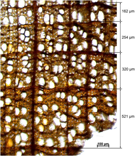
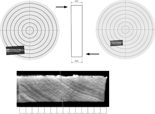
The panel is made of wood from small-leaved lime (Tilia cordata). Large-leaved lime is highly unlikely as only small-leaved lime is native to Russia and the Moscow region (Caudullo, Welk, and Ayanz Citation2020). The tree ring width is remarkably small. It varies from 0.2 to 0.6 mm and sometimes even 0.16 mm (). Obviously, the trees grew very slowly compared to lime trees in Central Europe.
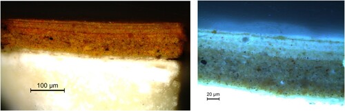
Figure 4. Cross-section of a sample of the panel: individual values of the tree ring widths are: 521, 320, 254, and 162 μm.
The wood of the crossbars (sliders) was also analysed. The characteristics found agree with those of larch (Larix spp.). Since the icon was made in Russia and the wood comes from Russia, it can be assumed that the material is from Siberian larch (Larix sibirica).
The icon to be investigated was stored in a conservation workshop with a fairly stable climate of 50% relative humidity for two months before measuring the wood moisture. The result for the lime wood is 5.2–5.8% in different depths of the icon.
Measuring by electrical resistance method highly depends on the species and the density of the wood that was used. It is quite inaccurate in the lower moisture ranges due to the high electric resistance in these ranges. To check the results, it was validated by the oven-drying method on a piece of another sample of lime wood from the back of the iconostasis of the Russian Memorial church. It turned out that the result of the electrical method shows a 0.7 percentage point lower value than the oven-drying method. The moisture content of the samples was 7.1% and 6.9% measured by the electrical method and 7.7% and 7.6% measured by the oven-drying method.
The data on the equilibrium moisture content of lime wood at a relative humidity of 50% and 24 °C in the literature varies between 6.0% and 7.9% (Rachwał et al. Citation2012, 369) and 7.1% and 9.2% (Jakieła, Bratasz, and Kozłowski Citation2008, 24) for ad- and desorption, respectively. In Popper and Niemz (Citation2009, 119), a value of 8.91% at a relative humidity of 50% and 20°C is stated. Although the measured values are at the lower end of the literature data, they are within the range of the sorption hysteresis and the natural variation of material parameters within one wood species.
In the larch wood crossbar, a wood moisture content of 10% was determined by the electrical method. However, during the measurement pine wood is assumed, as the measuring device does not have the specific resistance curve of larch wood. This seems reasonable, since, referring to Popper and Niemz Citation2009 (119), the characteristics of larch and pine are similar.
The average density of the whole icon including all ground and paint layers with this moisture content is approximately 0.51 g/cm3. This is determined by weighing the whole icon and, therefore, it represents an average value. The density of the single boards can vary considerably even within a single tree.
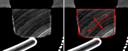
The crossbars are 20 mm longer than the width of the icon. We cannot be absolutely certain that at the time of manufacture or installation the panel was exactly as wide as the crossbars were long. But it is quite likely that the dimension in width reduced significantly. Even if we assume that the shrinkage is 10 mm, this means that the wood contained much more moisture or was fairly fresh when processed. From the X-ray cross-section of the upper crossbar (), it is seen that the deformation due to shrinkage is significant. The angle of one side is 83°, and the other is 90°. Due to more shrinkage in the tangential direction, the formerly identical angles have altered. This means that the wood of the crossbars contained more moisture (or was fresh) when processed.
Figure 5. X-Ray image of the upper crossbar (Photograph: Kerstin Hohdorf 2019). The red sketch represents the likely outline of the cross-section when the bar was made.
On the basis of the CT, a drawing of the construction was made (). The panel consists of twelve boards with simple butt joints. The joints run vertically but are not straight at a right angle. This could be an indication that the boards were manually rather than machine planed and joined.
Figure 6. Drawing of the construction of the panel based on CT, with three CT-sections of the panel (top, centre, bottom).
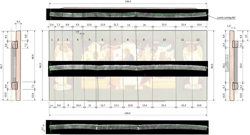
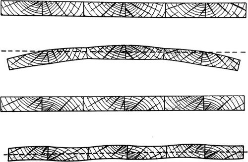
The position of the tree rings was made visible by CT. Thus, a fairly accurate drawing of each board including the position of the annual rings could be made (). In the drawings, the structure of the board is shown somewhat simplified because the structure of lime wood tends to not be straight like that of coniferous trees but is often bent. The annual rings are usually not perfectly circular, but rather wavy.
Figure 7. Example of a drawing of a single board of the panel. The wavy shape of the tree rings is visible.
The direction of the annual rings of boards 1–4, 6, 9, and 12 is oblique. On three boards, the annual rings are even parallel to the surface (boards 8, 10, 11). Only on boards 5 and 7 can we assume standing annual rings.
The adhesive used for the joints was not analysed. Due to the sensitivity to water, the reaction to heat and the smell, it is highly likely that it is glutin glue. The typically bright fluorescence of the glue in the joints under UV illumination also indicates glutin glue (see ). The glue layer of the joint itself varies in thickness. A sample for a cross-section was taken. It shows an ideal bond line of almost no width. The other joints show a glue layer of approximately 0.1 mm, sometimes even more, as can be seen in . The glue layer thickness in a joint always varies because it is virtually impossible to fit thick boards of 4 cm absolutely perfectly with a hand plane. Thus, in some areas of the joint, the boards touch each other while the other areas show a gap.
Figure 8. A cross-section of joint No. 4 from the back of the icon in normal light (left) and under UV illumination (middle). The glutin glue reveals itself by a bright bluish fluorescence. There is virtually no layer of glue. The glue penetrated the wood cells. On joint No. 11 (right), a glue layer of more than 0.1 mm is visible.
The sides of the icon were bevelled with a jack-plane, obviously after the ground layer and paint were applied, probably during the mounting in Leipzig when it was realized that the icon was too wide. The top edge was also cut with a coarse saw to fit the icon into the iconostasis.
The two crossbars on the back are wedge shaped, diminishing in width by 7 mm from left to right. The angles of the sides in the conical groove, where the crossbars fit in, were measured as 77° and 83°. The angle of the sides of the crossbar varies from 83° to even 90° (). However, the angles are not steep enough to hold the crossbars in place. Due to the cupping of the panel, the crossbars partially slid out of the rabbet. Actually, this can be seen as a lucky incident because otherwise more joints would have opened.
The Last Supper is located in the second row in the centre directly above the Tsar-door (). Currently, the gilded frame of the icon is screwed onto the panel by at least six long metal screws from the back of the icon. The icon with the mounted frame is then fixed to the beams with other screws. The original fixing was apparently different. The panel was first screwed to the beams and boards of the base construction like the icons of row 3–7 of the iconostasis. The gilded frame was mounted afterwards, also by means of long metal screws. In any case, the movement (shrinking and swelling) of the panel was blocked by the tight fixings and caused the open joints and cracks. This situation is unusual for iconostases in Russia, since the behaviour of wood was well known to the craftsmen and iconographers. One can assume that the people who fixed the icons onto the structure were not professionals.
Sizing and textile lamination
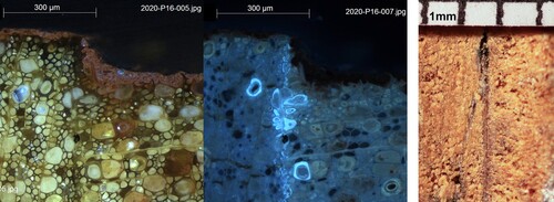
The wooden support was sized with an obvious thick glue layer of a thickness of 100–200 μm. According to FTIR analysis, it consists of protein glue with traces of chalk (calcium carbonate) and cellulose fibres. This layer can be identified by fluorescent staining with Sypro-Ruby® (). The fibres originate from a coarse textile (4/cm × 8/cm thread count). They were identified by polarized light microscopy as cotton fibres.
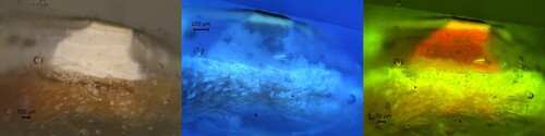
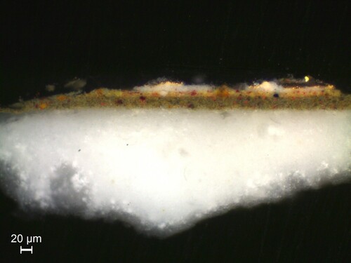
Figure 9. Cross-section of a sample from the green background: (left) visible light, (centre) UV fluorescence, (right) stained with Sypro Ruby® under blue light fluorescence (Leica I3) showing the entire stratigraphy, textile layer with thick sizing layer, ground layer with yellow discolouration, and double green paint layer.
Ground layer
On top of the sizing, a ground layer of 600–650 μm thickness is visible. It consists of approximately four comparatively thick layers (). According to FTIR analysis, the ground layer consists of chalk (calcium carbonate) and protein. Traces of sulphate and silicate were also detected. In the majority of the investigated spots, the ground layer was discoloured by a yellow tone from the surface into a depth of 70–400 μm, about the first layer. Here, besides chalk and silicate, drying oil was detected by FTIR in six spots (). This layer seems to be influenced by impregnation with oil from the surface. In contrast, the thick, multi-layered flesh tone () and one area of the foreground coated with metal foil () do not exhibit discolouration of the ground layer.
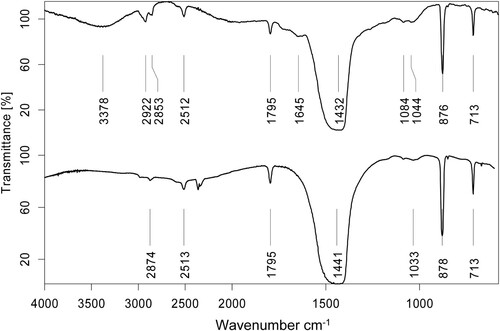
Figure 10. FTIR spectra (transmission mode): (top) yellow discoloured ground layer. Alkyl bands (2922 cm−1 and 2863 cm−1) indicate oil content, other absorptions are caused mainly by calcium carbonate and protein (1645 cm−1); (bottom) linseed oil reference.
The cross-sections of the paint on the front do not show a separate layer of binding medium on top of the ground layer indicating that no binding medium was applied to adjust the absorbency. The paint was obviously applied directly onto the ground layer. The reverse coating does not have any ground layer.
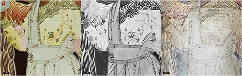
With infrared light, the sketch is visible under the bright paint layers if the sketch differs from the actual lines (, centre). Illuminated in reflected light, scratches – called graphja – are visible (Onasch Citation1968, 91). They often differ from the actual painted lines, too.
Figure 11. Detail of the right angel under (left) visible light, (centre) infrared, and (right) visible reflective light. In infrared, the lines of the sketch are visible. The scratches (graphja) are seen as dark lines when illuminated in reflected light. The bubbles in the ground layer are recognizable as round dark spots (right).
Paint layers
The paint layers generally are very thin (5–40 μm) and consist of one layer, except the green background which shows two layers of approximately 45 μm thickness together (). In contrast, the flesh tone () consists of a multi-layered structure of two paint layers and three glazes (in total c. 100–110 μm). Here, an increasing proportion of binder towards the top is observed, including the uppermost glaze.
Figure 12. Cross-section of a sample from flesh tone of the neck of the apostle in the left foreground, (left) visible light, and (right) UV fluorescence: on top of the white ground layer, two paint layers and then three very thin paint layers are visible.
The pigments and fillers as identified by several analytical methods (pXRF, SEM-EDX, PLM, FTIR) can be summarized as follows. Red, pink, and brown paints (six spots analysed) consist of iron oxide red (in most of the cases earth pigment, as proven by the content of clay minerals), iron oxide yellow (in most of the cases earth pigment, as proven by the content of clay minerals), cinnabar, and Paris blue (Prussian blue).
Yellow and ochre paints, including flesh tones (seven spots analysed) consist of iron oxide yellow (in most of the cases earth pigment), iron oxide red (in most cases earth pigment), cinnabar, carbon black, Paris blue, and viridian. Green paints (including the green background, four spots analysed) consist of iron oxide yellow (in most of the cases earth pigment) combined with Paris blue, iron oxide red (in most cases earth pigment), carbon black, and viridian. Blue paint (one spot analysed) consists of Paris blue and iron oxide red.
Grey paints (two spots analysed) consist of iron oxide red (earth pigment), indigo, and Paris blue. In several paints additionally lead white is detected. Gypsum, baryte, and silicates (e.g. china clay, quartz, and glass powder) are identified as fillers with FTIR. X-ray fluorescence (pXRF) additionally reveals indications for copper-, chrome-, lead-, and cadmium pigments.
Binding media
Protein, as well as oil, was detected by FTIR spectroscopy in eight of the investigated paint samples (). Protein was confirmed by reflection FTIR at two additional points.
Figure 13. FTIR spectra (transmission mode): (top) grey paint, (middle) green paint after extraction prior to GC-MS analysis, (bottom) egg yolk reference. Absorptions at 2930 cm−1, 2860 cm−1, and 1735 cm−1 indicate oil content. Weaker absorptions at 1650 cm−1 (shoulder) and 1540 cm−1 indicate protein. Other absorptions in the spectrum of the green paint (middle) are caused mainly by pigments: Prussian blue (2091 cm−1), lead white (1411 cm−1, 684 cm−1), and clay minerals (3700 cm−1, 3623 cm−1, 1036 cm−1, 915 cm−1).
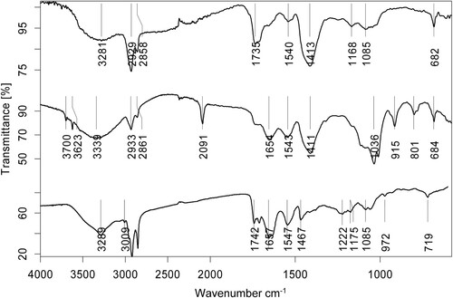
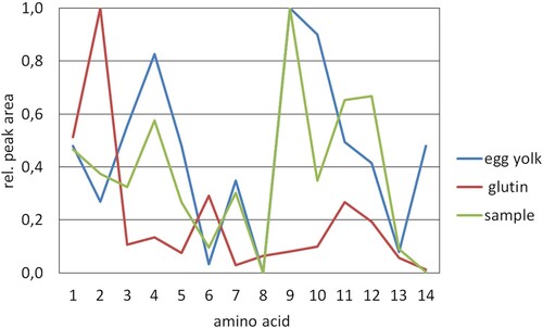
One sample of green paint was analysed with GC-MS for oils, fats, wax, and resin. The fatty acid profile, particularly the dicarbonic acids (e.g. azelaic acid) as typical ageing products, indicate a highly oxidized drying oil. The ratio of palmitic acid to stearic acid of P/S = 2.2 lies in the range given in the literature for linseed oil (P/S = 1.0–3.3) (Mills and White Citation1994, 33), although it might be influenced by the content of beeswax (P/S = 23) (Mills and White Citation1994, 50). Furthermore, this value cannot reliably be used as an evidence for the biological origin of aged oils (Bonaduce et al. Citation2012). Derivates of abietic acid indicate conifer resin. Additional traces of beeswax are identified (e.g. tetradecanoic acid, paraffins with odd-numbered alkanes). Further specific components indicate polysaccharides (maleic acid) or contaminants. The analysis of amino acids by GC-MS of the same paint sample revealed a high accordance with an egg yolk standard. Although decisive proof for egg (e.g. cholesterol) was not detected, a mixture of egg and oil can be assumed ().
Figure 14. Results of GC-MS analysis of amino acids in a green paint sample, depicted as amino acid profile based on normalized peaks: 1 = L-alanine 2TBDMS derivative, 2 = glycine 2TBDMS derivative, 3 = L-valine 2TBDMS derivative, 4 = L-leucine 2TBDMS derivative, 5 = isoleucine 2TBDMS derivative, 6 = L-proline 2TBDMS derivative, 7 = L-aspartic acid 2TBDMS derivative 8 = L-hydroxyproline 2TBDMS derivative, 9 = L-serine 3TBDMS derivative, 10 = L-phenylalanine 2TBDMS derivative, 11 = L-aspartic acid 3TBDMS derivative, 12 = L-glutamic acid 3TBDMS derivative, 13 = L-lysine 3TBDMS derivative, 14 = L-tyrosine 3TBDMS derivative.
Metal leaf applications
Some areas on the paintings such as ornaments and letters are covered with a metal leaf application consisting of gold as found by pXRF. The metal foil was applied on a white preparation layer of approximately 10 μm thickness () which is composed of lead white, silicate, quartz, protein, and oil according to FTIR analysis. Generally, the composition of the preparation layer resembles that of the paint. A yellow retouching layer is partially applied on areas of missing metal application. Elemental analysis (SEM-EDX) reveals hints of titanium white as well as iron-, chromium-and cadmium-containing pigments.
Figure 15. Cross-section of a sample from the metal leaf application on the bench in the left foreground, under visible light: on top of the white ground layer two paint layers, a white preparation layer, and gold foil are visible.
Varnish coating
Under UV irradiation, the olifa (traditional oil varnish on Russian icons) shows a yellowish fluorescence. Two more layers of varnish are identifiable. A varnish layer with a pale yellowish fluorescence covers the whole surface of the icon. The fluorescence is not as strong as the fluorescence of the olifa or the layer is not as thick as the remains of the olifa. A third layer of varnish was applied only partially. The fluorescence is bluish green as can be seen in .
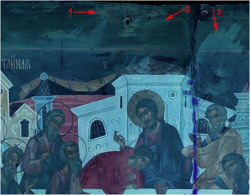
Figure 16. Detail under UV irradiation (contrast enhanced): arrow 1 indicates yellowish fluorescent islets that can be interpreted as remains of the partially removed upper layer of the olifa, arrow 2 indicates a second varnish layer that can be found on the entire surface, and a third varnish layer (arrow 3) that was applied partially. Retouching and overpainting lying above the varnish layers appear darker, as can be seen on the joint (on the right side of the photograph).
One sample was taken from the second varnish layer, where no bluish green fluorescence is visible. It is not possible to completely separate the varnish layers, so the sample contains traces of the olifa as well as the first varnish. The GC-MS analysis of this sample reveals drying oil with a fatty acid profile different from that of the green paint from the front and the reverse coating. A lower content of azelaic acid and the content of oleic acid indicate a lesser degree of oxidation. Furthermore, markers for animal fat (e.g. squalene) were identified. Derivates of abietic acid (e.g. dehydroabietate) indicate conifer resin. A considerable number of compounds typical for beeswax were detected (e.g. tetradecanoic acid, paraffins with odd-numbered alkanes). Furthermore, three components reveal a composition different from the oil-resin-mixture as analysed for the green paint: marker substances indicate the triterpenoid resins dammar (e.g. hexakisnordammaran) and mastic. Further specific substances indicate diterpenoid copal resin.
Reverse side coating
The reverse side is coated with a double layer of red paint with an overall thickness of approximately 30 μm, separated by an intermediate varnish. No sizing was observed on the cross-section under light microscopy. According to the pXRF and FTIR analyses, the red paint contains red earth with iron oxide, China clay, and quartz, baryte, gypsum, and a carbonate pigment. The GC-MS analysis of the binder reveals a pattern of fatty acids and dicarbonic acids (e.g. azelaic acid) typical for a strongly oxidized drying oil. Derivates of abietic acid (e.g. dehydroabietate) indicate conifer resin. Some markers of beeswax (e.g. tetradecanoic acid) are present as well. Further components can be caused by polysaccharides (citric and maleic acids) or contamination. In contrast to the green paint on the front side, the FTIR spectrum of the paint after extraction prior to GC-MS analysis does not show absorption bands of protein.
The bottom face is covered with the ground layer (levkas) without the textile lamination. Presumably, this had also been the case on the side faces and the top face when the icon was painted. As mentioned above, the upper edge and the sides were cut back during the mounting in the iconostasis in 1912. The surface of the upper side and the levkas of the bottom now have a layer of a wax-like substance (melting point of 60°C), very likely applied to reduce the diffusion of water vapour. However, it is not possible to identify whether it was applied during the mounting in 1912 or later. The side faces do not have such a coating.
Former restoration campaigns
The icons of the iconostasis have been restored several times as can be seen on the icons themselves. However, it is impossible to find out when the measures were carried out. The files of the State Office for Monument Preservation indicate several campaigns took place in which the icons could have been treated: 1927/28, 1945 (Schüppel Citation1956), 1963 during the preparation for the 50th anniversary, 1988, and 1995 (Derzhavina Citation2015, 67). The last treatment was carried out in 2018.
The olifa was also removed on the area that is covered by the frame. One layer of varnish was applied completely and a second layer partially. Numerous retouchings and small overpaintings were applied as can be seen under UV irradiation (). The open joints that can be seen in a photograph from 1987 were closed and secured with metal staples at the upper and lower edges, probably during the restoration in 1995. In 2017, the joint between boards 5 and 6 opened due to the shrinkage of the panel and the tight fixation to the frame. It was re-adhered with a mixture of polyvinyl acetate and cotton-like fibres by a conservator of the Russian parish. This joint opened again and was at another time reglued with polyvinyl acetate in 2019. This time, a very thin wedge of limewood was inserted between the panels from the reverse side to reduce the tension caused by the cupping of the panel.
Overall, the condition of the icon can be summarized as very stable. The ground and paint layers do adhere very well and are not at all endangered, which confirms that the art technique of Emelyanov does fulfil its purpose. The cupping of the panel nevertheless has to be accepted. The fixation of the icon to the frame recently was improved by using thinner screws that allow movement due to shrinkage and swelling of the panel.
Discussion
The boards used were not the best choice for making a panel, particularly boards 8, 10, and 11 (). A closer look at the arrangement of the boards indicates that the common rule to join the boards in a manner that the panel stays fairly flat when drying (; Spannagel Citation1954, 51) seems to have been ignored.
Figure 17. Drawing from Spannagel (Citation1954, 51) showing the correct method to join boards to prevent cupping of a panel.
This lack of quality could be interpreted as sacrificing the carpenter's sacred rules to efficiency. Considering that the workshop of Emelyanov was engaged in making another two iconostases in this period as mentioned before (Derzhavina Citation2015, 48) and the Leipzig iconostasis was produced within one year, one can understand that the character of the whole process should be called industrial rather than artisanal. It can also be assumed that Emelyanov hired an inexpensive contractor, who was simply unaware of the quality standards for the manufacturing of panels for icons.
Another interpretation of the arrangement of the boards on this icon could be that it was just not important to the panel makers because it was known that all icons cup convex sooner or later. Considering that most of the icons in the Leipzig iconostasis are in good condition (apart from the open joints that are due to the tight fixation), the position of the annual rings actually seems to play only a minor role.
The remarkable thick sizing layer with the cotton textile is mentioned in an almost contemporary source. In 1946 Schneider (Шнейдер and Федоров Citation2002, 243–244) gives detailed instructions concerning the sizing and the textile (Russian: pavoloka). It is described that the surface is pre-sized at least twice. After drying of the sizing, another thick layer of glue is applied on which a textile that is soaked in the glue is laid. This could result in a very thick glue layer like on the icon Last Supper. According to the literature for guilders, the lower layer should be able to absorb the binding medium of the next layers (Kellner Citation1992, 16). A glue layer of up to 0.2 mm means that the surface is sealed. Nevertheless, there are only very few areas of loosened paint on the icons of the entire iconostasis. Thus, the technique was obviously suitable to prevent the coating (meaning the whole package of sizing, textile, ground layer, paint layer, and varnish layers) from chipping off. The reconstruction tests showed that it is quite difficult to obtain a glue layer of 0.2 mm thickness by only one application. Therefore, it is more likely that this layer was intentionally made that thick.
The observed ground corresponds to the traditional multi-layered application of chalk, bound with animal glue (Russian: lefkas) (Onasch Citation1968, 88; Högy Citation1978, 121; Шнейдер and Федоров Citation2002, 246). The slightly wavy character of the surface shows that it was not smoothened very thoroughly with abrasive tools or paper. One can find even small bubbles that were not filled or removed (, right). In traditional icon painting, the image was transferred to the ground in different ways (pouncing, stencils, and just painting with charcoal). On the icon Last Supper, these transferring techniques are not visible. However, the infrared photograph shows the drawing (risunok) lines that were drawn probably with a thin brush (, middle). Clearly visible are the scratches of the outlines and the main internal elements of the drawing in the ground layer (graphja) (, right). The scratches allow the sketch to be seen even when dark colours are used and the drawing is covered (Onasch Citation1968, 89–91).
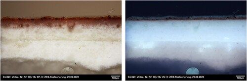
For painting the icon both traditional pigments, mostly of natural origin (red and yellow iron oxide earth pigment, cinnabar, carbon black, lead white, gypsum, silicates) as well as modern pigments (e.g. Paris blue, viridian, baryte, cadmium-based pigment) were used. Among the possible sources for the oil detected in the top layer of the preparation, the impregnation with oil prior to painting or absorbed oil from the paint seems unlikely because some areas (e.g. gilded area or flesh tone) do not show oil in the ground layer and the paint layers generally are very thin. In fact, impregnation with oil subsequent to painting seems much more probable as it resembles the traditional way of painting icons (olifa coating) as described below. This treatment could be recognized in the cross-sections of samples taken from the work under investigation here where it obviously has penetrated the paint into the ground layer. Otherwise, the thick, multi-layered flesh tone and the gilded areas do not show oil in the ground as the layers probably hindered the olifa from penetrating ( and ). Furthermore, this assumption is supported by a very similar appearance of a cross-section under microscopic investigation sampled from a technological replica that was produced using the results of this investigation and traditional icon painting technique ().
Figure 18. Cross-section of a sample from a replica manufactured according to the traditional technique of icon painting, (left) visible light, (right) UV fluorescence. The impregnation of the white ground layer with the oil coating (olifa) into a depth of about 250–300 μm is visible especially under UV fluorescence. (Photographs by S. Reuther, Landesamt für Denkamlpflege, Dresden).
The structure of the paint layer corresponds in general to the traditional way of painting an icon as described in the literature (Onasch Citation1968; Högy Citation1978; Weissmann Citation2012): earth or natural colours are mixed with egg yolk plus a thinning liquid. This is supported by the protein detected by FTIR in most of the paint samples as well as the egg proteins confirmed by GC-MS analysis of one green paint sample in the work under investigation here. Consequently, the oil detected in the majority of the analysed paint samples can be explained by the olifa coating rather than a painting medium mixed from egg and oil. According to the GC-MS analysis, it contains diterpenoid resins along with the drying oil. On the other hand, the markers for triterpenoid resins (dammar, mastic), as well as copal analysed in a second varnish sample probably, are not components of the original olifa.
The polysaccharides that are detected in the sample might come from the thinning liquid. In the literature, kvass, a kind of beer made from bread, is mentioned as well as diluted fig milk (Onasch Citation1968, 95). Thinned wine and vinegar are also known as a diluent (Гренберг Citation2004, 149, 161). Modern iconographers use wine, but as in the past wine was considered an expensive imported product, kvass was probably preferred.
Three layers of varnish can be detected (). The first is the olifa that has a yellowish-green fluorescence. Numerous yellowish-green fluorescent islets indicate that this layer was partially removed during a former restoration campaign. The second varnish layer found on top of the remainders of the olifa consists of resins like dammar, mastic, and copal. It was very likely applied during one of the restoration campaigns. In , one can see another layer of a more blueish fluorescing varnish that was incompletely applied (: arrow 3).
From the very similar composition of the fatty acid fraction and the degradation products resembling aged linseed oil, contained both in the green paint on the front side and the red paint on the reverse, it can be concluded that similar oil was used for the olifa and the reverse side coating.
Conclusions and outlook
As a part of the VirtEx project, the technology of the icon Last Supper of the iconostasis in the Russian Memorial Church Leipzig by Emelyanov was thoroughly investigated. The results presented are the basis for the appropriate and realistic material and structural modelling as well as for production of realistic copies and replicas.
The examination gives valuable information on the art technique of Emelyanov’s workshop. Obviously, with the Leipzig icon Emelyanov basically followed the traditional icon painting technique but deviated in details such as the application of some modern pigments, the thick starch-based sizing layer, and the choice of wooden boards (specifically the position of the annual rings). How consciously Emelyanov proceeded here, whether he revived the traditional technique in the course of his preoccupation with the Old Masters or practised the traditional technique from the outset, can only be found in the course of examining his oeuvre as a whole. How representative the Leipzig iconostasis (concerning the choice of wood and art technique) is to the icon painting technique of the beginning of the twentieth century in Russia in general remains to be investigated.
Of special interest to the VirtEx project are the very thick glutinous glue layer and the olifa, which penetrated the painting layer and the primer very deeply. The thick and reinforced glue layer might have an influence on mechanical behaviour. Both details have an effect on the vapour permeability of the coating and are therefore important for the modelling work.
The main subsequent steps towards the goal of the VirtEx project are:
– production of the mentioned technological replicas, a copy and test specimens on the basis of this technological investigation;
– determination of the mechanical and hygric parameters of the wood and coatings (ground, paint, and varnish layers);
– long-term experiments on the replicas and the copy with exact measurements of the climate, the wood moisture content, and three-dimensional photogrammetrical measurements;
– material modelling with the determined material parameters of lime wood, bond lines, and ground, paint, and varnish layers;
– virtual experiments, i.e. numerical simulation of the icon under different climate conditions, considering the time and hygro-mechanical dependencies with the evaluation of damage potential, including damage simulation;
– evaluation of the quality of the models and methods by comparing the simulation results to the measurement results of the replicas and the copy.
Publications on the other parts of the project will follow.
Acknowledgements
The authors are grateful to the Russian Church in Leipzig and the archpriest Father Alexei Tomjuk, who allowed us to investigate the icon. Many thanks also go to the Landesamt für Denkmalpflege Sachsen (Saxon State Office for the Preservation of Monuments), in particular to Manfried Eisbein, on whose idea the project was initiated. Many thanks are due to Alexander Kozmin and Galina Maximova from the Surikov Institute Moscow for advice and help with the preparation of the copy and replicas that were produced as a part of the project, and especially to Natalja Sharova for painting the copy of the icon. We are very grateful to Dr Kerstin Hohdorf (Nuclear Medicine Practice Leipzig) for performing the computer tomography of the icon and to Sylvia Hoblyn for the R-FTIR measurements. Great thanks to Fokus GmbH Leipzig for the infrared photograph of the icon.
Disclosure statement
No potential conflict of interest was reported by the author(s).
Additional information
Funding
References
- Aggeev, P. Y. 1886. “Technical Notes of Painting. Paints of Old Russian Iconographers.” Vestnik Izyaschnyh Iskussnv (Bulletin of Fine Arts) T 4 (6): 450–464.
- Ashley-Smith, J., A. Burmester, and M. Eibl, eds. 2013. Climate for Collections. Standards and Uncertainties. Munich: Archetype Publications Ltd and Doerner Institut.
- Bonaduce, I., L. Carlyle, M. P. Colombini, C. Duce, C. Ferrari, E. Ribechini, P. Selleri, and M. R. Tiné. 2012. “New Insights Into the Ageing of Linseed Oil Paint Binder. A Qualitative and Quantitative Analytical Study.” PLoS One 7: e49333.
- Bosco, E., A. S. J. Suiker, and N. A. Fleck. 2020. “Crack Channeling Mechanisms in Brittle Coating Systems Under Moisture or Temperature Gradients.” International Journal of Fracture 225: 1–30.
- Bosco, E., A. S. J. Suiker, and N. A. Fleck. 2021. “Moisture-Induced Cracking in a Flexural Bilayer with Application to Historical Paintings.” Theoretical and Applied Fracture Mechanics 112: 102779.
- Bratasz, L. 2013. “Allowable Microclimatic Variations for Painted Wood.” Studies in Conservation 58: 65–79.
- Caudullo, G., E. Welk, and J. S. Ayanz. 2020. Chronological Data for the Main European Wood Species, Mendeley Data, V9. Euforgen 2020. European Forest Genetic Resources Programme. Accessed April 12, 2021. http://www.euforgen.org/species/tilia-cordata/.
- Christache, R., I. Sandu, A. Simionescu, V. Vasilache, A. Budu, and I. Sandu. 2015. “Multi-Analytical Study of the Paint Layers Used in Authentication of Icon from XIXth Century.” Revista de Chimie 66: 1034–1037.
- Colombini, M. P., F. Modugno, S. Giannarelli, R. Fuoco, and M. Matteini. 2000. “GC-MS Characterisation of Paint Varnishes.” Microchemical Journal 67: 385–396.
- Derzhavina, V. 2015. Die kulturelle Bedeutung der Russischen Gedächtniskirche zu Leipzig. Gedächtniskirche zur Russischen Ehre in Leipzig 1913-2013, 92–104. Beresta, St. Petersburg.
- Duin, P. V., and N. Kos. 2014. The Conservation of Panel Paintings and Related Objects. Den Haag: NWO.
- Durnovo, L. A. 1926. Old Russian Painting Technique. Materials of Techniques and Conservation Technologies. Leningrad: Russian Museum.
- Filatov, V. V. 1961. Russian Easel Tempera Painting. Techniques and Restoration. Moscow: Iskustvo.
- Fuhrman, A., V. Hietschold, M. Eisbein, K. Püschner, and B. Weiß. 2019. “Extraktion ölgetränkter Holzobjekte.” VDR Beiträge 16: 73–83.
- Grenberg, Y. I. 1971–1975. Sketches of the History of the Development of Technical and Technological Research of Paintings. Papers of the All-Russian Central Scientific-Research laboratory for Conservation and Restoration of Museum Art-works (VtsNILKR – Всероссийская центральная научноисследовательская лаборатория по консервации и реставрации музейных художественных ценностей), 26–29.
- Grenberg, Y. I. 1976. Fundamentals of Museum Preservation and Research of Easel Artwork. Part 2: Primary Analytical Methods of Technical and Technological Research. Moscow: Iskusstvo.
- Гренберг, Ю. И. 2004. От фаюмского портрета до постимпрессионизма. История технологии станковой живописи: две тысячи лет эволюции. Москва: Искусство.
- Guryanov, V. P. 1906. Two Local Icons of the Holy Trinity in Holy Trinity Cathedral of the Holy Trinity-St. Sergius Lavra and Their Restoration. Moscow: Pechatnia A. I. Snegirevo.
- Hagan, E., E. Quasney, and M. Mecklenburg. 2004. “A Parametric Analysis of Relative Humidity. Effects on Traditional Panel Paintings.” MRS Proceedings 852: OO2.8.
- Högy, T. 1978. Russische Ikonen. Gießen: Wilhelm Schmitz Verlag.
- IIC. 2014. IIC – ICOM CC Declaration on Environmental Guidelines. International Institute of Conservation. Accessed April 12, 2021. https://www.iiconservation.org/node/5168.
- Jakieła, S., Ł Bratasz, and R. Kozłowski. 2008. “Numerical Modelling of Moisture Movement and Related Stress Field in Lime Wood Subjected to Changing Climate Conditions.” Wood Science and Technology 42: 21–37.
- Kellner, H. 1992. Vergolden. Das Arbeiten mit Blattgold. München: Callwey.
- Konopka, D., C. Gebhardt, and M. Kaliske. 2017. “Numerical Modelling of Wooden Structures.” Journal of Cultural Heritage 27S: 93–102.
- Konopka, D., and M. Kaliske. 2018. “Virtual Experiments on Stringed Wooden Instruments. Influence of Mechanical and Climate Loading.” In Wooden Musical Instruments. Different Forms of Knowledge. Book of End of WoodMusICK COST Action FP1302, edited by M. A. Pérez and E. Marconi, 291–309. Paris: Cité de la Musique - Philharmonie de Paris.
- Kupczak, A., M. Jędrychowski, M. Strojecki, L. Krzemień, Ł Bratasz, M. Łukomski, and R. Kozłowski. 2018. “A Web-Based Decision-Supporting Tool for Assessing Risk of Physical Damage Using Various Failure Criteria.” Studies in Conservation 63: 151–155.
- Luimes, R. A., and A. S. J. Suiker. 2021. “Numerical Modelling of Climate-Induced Fracture and Deformation in Wood: Application to Historical Museum Objects.” International Journal of Solids and Structures 210–211: 237–254.
- Luimes, R. A., A. S. J. Suiker, A. J. M. Jorissen, P. H. J. C. van Duin, and H. L. Schellen. 2018. “Hygro-mechanical Response of Oak Cabinet Door Panels Under Relative Humidity Fluctuations.” Heritage Science 6: 1–23.
- Łukomski, M., M. Strojecki, B. Pretzel, N. Blades, V. L. Beltran, and A. Freeman. 2017. “Acoustic Emission Monitoring of Micro-Damage in Wooden art Objects to Assess Climate Management Strategies.” Insight 59: 256–264.
- Mecklenburg, M. F., C. S. Tumosa, and D. Erhardt. 1998. “Structural Response of Painted Wood Surfaces to Changes in Ambient Relative Humidity.” In Painted Wood. History and Conservation, edited by V. Dorge and F. C. Howlett, 464–483. Los Angeles: The Getty Conservation Institute.
- Michalski, S. 2009. “The Ideal Climate, Risk Management, the ASHRAE Chapter, Proofed Fluctuations, and Towards a Full Risk Analysis Model.” In Proceedings of Experts’ Roundtable on Sustainable Climate Management Strategies, Tenerife 2007, edited by F. Boersma. Los Angeles: Getty Conservation Institute. Accessed April 12, 2021. https://www.getty.edu/conservation/our_projects/science/climate/climate_experts_roundtable.html.
- Mills, J. S., and R. White. 1994. The Organic Chemistry of Museum Objects. 2nd ed. Oxford: Butterworth-Heinemann.
- Naumova, M. M. 2018. Late Antiquity – The Middle Ages – The Renaissance – Painting Materials and Techniques. A Collection of Articles and Statements. Moscow: Indrik.
- Nicolaus, K., and C. Westphal. 1999. The Restauration of Paintings. Köln: Könemann Verlagsgesellschaft.
- Niemz, P., and W. Sonderegger. 2017. Holzphysik. Physik des Holzes und der Holzwerkstoffe. München: Hanser-Verlag.
- Onasch, K. 1961. Ikonen. Berlin: Union.
- Onasch, K. 1968. Die Ikonenmalerei. Grundzüge einer systematischen Darstellung. Leipzig: Köhler & Amelang.
- Popper, R., and P. Niemz. 2009. “Wasserdampfsorptionsverhalten ausgewählter heimischer und überseeischer Holzarten.” Bauphysik 31: 117–121.
- Rachwał, B., Ł Bratasz, M. Łukomski, and R. Kozłowski. 2012. “Response of Wood Supports in Panel Paintings Subjected to Changing Climate Conditions.” Strain 48: 366–374.
- Sandu, I., S. Bracci, I. Sandu, and M. Lobefaro. 2009. “Integrated Analytical Study for the Authentication of Five Russian Icons (XVI–XVII Centuries).” Microscopy Research and Technique 72: 755–765.
- Sandu, I., A. Roque, P. Matteini, S. Schäfer, G. Agati, C. Correia, and J. Viana. 2012. “Fluorescence Recognition of Proteinaceous Binders in Works of Art by a Novel Integrated System of Investigation.” Microscopy Research and Technique 75: 316–324.
- Шнейдер, ИВ, and ПА Федоров. 2002. Техника иконописи. Руководство к практическому изучению писания православных икон по приемам первых иконописцев. В: Вздорнов Г. И., Залесская З. Е., Лелекова О. В.: <Общество «Икона» в Париже. Т. 2., Прогресс-Традиция, Москва, 241–280.
- Schüppel, H. 1956. Brief des Beauftragten des Institutes für Denkmalpflege des Rates der Stadt Leipzig an das Institut für Denkmalpflege Dresden 16.08.1956. Akte zur Russischen Gedächtniskirche Leipzig im Landesamt für Denkmalpflege Sachsen.
- Schweinfurth, P. 1930. Geschichte der Russischen Malerei im Mittelalter. Haag: Martinus Nijhoff.
- Shchavinsky, V. A. 1935. “Essays on the History of Painting Techniques and Paint Technique in Ancient Russia.” In News of the State Academy of the History of Material Culture, 115. Moscow-Leningrad: Gosudarstvennoe sotsialno-ekonomicheskoe isdatelstvo (State Social-Economical Publishing House).
- Spannagel, F. 1954. Der Möbelbau. Ein Fachbuch für Tischler, Architekten, Lehrer und Liebhaber. Ravensburg: Otto Maier.
- Stratis, J. A., C. Makarona, D. Lazidou, E. G. Sánchez, A. Koutsoudis, M. Pamplona, R. Pauswein, G. Pavlidis, S. Simon, and N. Tsirliganis. 2014. “Enhancing the Examination Workflow for Byzantine Icons: Implementation of Information Technology Tools in a Traditional Context.” Journal of Cultural Heritage 15: 85–91.
- Tantideeravit, S., M. N. Charalambides, D. S. Balint, and C. R. T. Young. 2013. “Prediction of Delamination in Multilayer Artist Paints Under low Amplitude Fatigue Loading.” Engineering Fracture Mechanics 112–113: 41–57.
- Weissmann, G. 2012. Techniques of Traditional Icon Painting. Tunbridge Wells: Search Press Ltd.
- Wood, J. D., C. Gauvin, C. R. Young, A. C. Taylor, D. S. Balint, and M. N. Charalambides. 2018. “Cracking in Paintings due to Relative Humidity Cycles.” Procedia Structural Integrity 13: 379–384.
- Yakovleva, A. I. 1987. Techniques of Old Russian Painting (Pre-Mongolian Period). Dissertation at All-Union Scientific-Research Institute of Arts. Moscow.