
 ?Mathematical formulae have been encoded as MathML and are displayed in this HTML version using MathJax in order to improve their display. Uncheck the box to turn MathJax off. This feature requires Javascript. Click on a formula to zoom.
Abstract
This work elaborately conducts the coupled vibration analysis of suspended monorail train and curved bridge (SMTCB) considering a nonlinear wheel-track contact relation. First, a high-efficiency coupled dynamic model of the SMTCB is developed based on a co-simulation method where the train subsystem is established using the multi-body dynamics software UM and the curved bridge subsystem is built adopting the finite element software ANSYS, whose modal information is extracted to put into the UM software; Two subsystems of the train and bridge are coupled by an improved wheel-track contact model (IWTCM) that considers the real nonlinear radial stiffness of a suspended monorail rubber tire. Then, the effects of the extracted modal orders of the bridge on vehicle-bridge vibrational responses are analyzed and discussed in detail, and the minimum modal orders extracted of the bridge that guarantee the convergence and accuracy of the proposed model are also obtained. Subsequently, the vibrational responses obtained by numerical simulation and field test are compared when the vehicle runs on a curved bridge, validating the reliability of the developed model. On this basis, by comparing the vehicle-bridge vibration responses between the traditional FIALA tire model and the IWTCM, some remarkable differences are distinguished, revealing the significances and advantages of adopting the IWTCM. Finally, employing the developed model, the vehicle-curved bridge coupled vibration features are investigated comprehensively and several key parameters are also chosen reasonably. The research results may provide some useful guidance for the design of the SMTCB.
1. Introduction
Nowadays, the urbanisation is in a stage of rapid development, and more and more people are gathering in big cities. Urban transportation systems are facing serious challenges. To mitigate the pressure of urban traffic congestion, many big cities have constructed large-capacity rail transit systems, such as subway and light rail [Citation1,Citation2]; however, they need large construction investment, a long construction cycle, and a high cost of operation and maintenance. Therefore, it would be unrealistic to build them in every city. The suspended monorail system (SMS), as a new sky traffic system, has many outstanding advantages of small investment, short construction period, low noise, small footprint, small turning radius and good landscape, etc., which would be a good choice for improving the urban traffic jam [Citation3–5].
Compare with the conventional railway system, the SMS has a special vehicle structure, bridge type and wheel-track relation, so the monorail vehicle-bridge interactive features may have obvious discrepancies. It is necessary to conduct a comprehensive investigation on the suspended monorail vehicle-bridge interaction (VBI). So far, a number of investigation on the railway VBI has been carried out [Citation6], such as theoretical modeling methodology [Citation7–11], numerical integration method [Citation12,Citation13], nonlinear wheel-rail contact behaviour [Citation14–17], vehicle-bridge interactive features [Citation18], vehicle running safety evaluation subjected to moderate earthquake and derailment impacts [Citation19,Citation20] and seismic response control of bridge [Citation21,Citation22], etc. With regard to the straddle-type monorail, some literatures also reported the vehicle-beam interaction features [Citation23], dynamic performances of vehicle and beam [Citation24, Citation25] and key parameters optimisation [Citation26], etc. In terms of the SMS, several scholars conducted a preliminary investigation. Cai et al. [Citation27] and He et al. [Citation28,Citation29] proposed a refined vehicle-bridge coupled dynamic model of the SMS by using the ANSYS parametric design language (APDL), and it was preliminarily validated with field tests; in this approach, the bridge considered a full-mode finite element model (FEM) and its vibration responses were solved with the direct stiffness method (DSM) in ANSYS. This approach could comprehensively assess the vehicle-bridge dynamic performances, including the vehicle vibrational responses, bridge vibration level and structural strength of the bridge; however, the simulation process would cost a lot of computing time due to the solution of the enormous (FEM). Bao et al. [Citation30] and Jiang et al. [Citation31] built a VBI model of the SMS employing a co-simulation method where the vehicle model is established using the multi-body dynamics software, and the bridge model is built using the finite element software, whose main modes is extracted and put into the multi-body dynamics software to couple with vehicle model; in this methodology, the degrees of freedom (DOFs) of the bridge were reduced by extracting the low-order vibration modes, and the bridge vibration responses were obtained adopting the modal superposition method (MSM). The co-simulation method significantly improves calculation efficiency, which would be an effective way to model the vehicle-bridge interaction with an enormous bridge model. Noteworthily, in the co-simulation method, how many bridge modes should be extracted is a fundamental and key question, which would directly influence the reliability and accuracy of the simulation results, especially for the suspended monorail beam with an open bottom; however, the research about this aspect is reported rarely in the existing literature. Therefore, it is essential for this issue to conduct a detailed investigation.
The wheel-track relation is the core of connecting the vehicle and bridge subsystems, which has important influences on the vehicle-bridge interactive features. In the modeling of monorail vehicle-bridge interaction, most of the existing study directly adopt the point-contact tire model with the linear stiffness or the classic tire contact models used in the road car [Citation23–27,Citation29–31], such as the FIALA tire model. Noteworthily, the monorail vehicle adopts a rubber tire to drive, thus the contact behaviour between the tire and the track has strong nonlinear mechanical characteristics due to the properties of the rubber materials. Generally, the radial stiffness of the tyre under different radial deformation would be obviously different, which usually increases with an increase of the radial compression displacements. Adopting the wheel-track contact model with the linear radial stiffness means that the tyre radial stiffness always keeps the same under different compression deformation, which cannot fully reflect the change of the tyre radial stiffness along with radial compression deformation under actual operating conditions. Besides, compared with the road car tire, the rubber tire of the suspended monorail vehicle has a larger structure size and load capacity, whose performance parameters would be significantly different, especially the radial stiffness of the tire. Therefore, employing the point-contact tire model with the linear stiffness and the classic tire contact models with the performance parameters of the common car tire may cause a large calculation deviation. To better model the wheel-track radial contact behaviour in the SMS, He [Citation28] developed a patch-contact tire model by adopting the equally distributed spring-damping elements; this tyre model can well model the radial contact behaviour because of considering contact patch, especially simulating the local impact action, however, the simulation of longitudinal and transverse contact characteristics was greatly simplified, in which the side force and aligning torque of the tyre were considered to be linearly related to its lateral slip angle and the longitudinal creep and sideslip of the tire were also not considered in this tire model. Therefore, the existing study on the wheel-track contact models in monorail system is still not sufficient enough. To accurately evaluate the monorail vehicle-bridge vibrational responses, it is essential to further improve the tire contact model.
Additionally, the suspended monorail vehicle has an outstanding advantage of a small turning radius, and it would run through many curved bridges in the actual operating lines. However, the existing study mainly focuses on the monorail train-straight bridge, and the investigation on the vehicle-curved bridge interactive characteristics is relatively less.
In the current study, the coupled vibration analysis of suspended monorail train and curved bridge (SMTCB) is elaborately carried out. Firstly, an improved wheel-track contact model (IWTCM) is proposed on the basis of the traditional FIALA tire model, which considers the real nonlinear radial stiffness of a suspended monorail rubber tyre. Following which, based on the theory of multi-body dynamics and finite element method, a coupled dynamic model of the SMTCB is established where the bridge model considering some main low-order modes is coupled with the vehicle dynamic model through the IWTCM. Then, the effects of the extractive bridge modal orders on the convergence and accuracy of the proposed model are studied, and the simulation results are also validated with experimental results. On this basis, the dynamic responses between the traditional FIALA tire model and the IWTCM are compared in detail, and the vehicle-curved bridge interactive characteristics are also studied comprehensively. The research results may be helpful to the modeling of the vehicle-curve bridge interaction and the optimal design of the SMS.
2. Analysis method for the train-curved bridge interaction
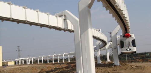
The SMS, as a new rail transit type, has a special vehicle structure, bridge type and wheel-track system. The train runs under the box beam and the wheel-track system is installed inside the box beam, which can avoid the risk of vehicle derailment because of the novel structure design. In the actual operating line, the monorail train would travel on the curved bridge with different radiuses, as shown in Figure . To study the dynamic responses of the suspended monorail train-curved bridge system, this work intends to establish a high-efficiency coupled dynamic model based on a co-simulation method.
Figure 1. Suspended monorail train-curved bridge system.
2.1. Vehicle subsystem
Some main structural features of suspended monorail vehicle are summarised as follows:
Each vehicle includes two bogies, two bolsters, two hanging beams, two articulated four-link suspension devices, a car body and the suspension systems.
Each bogie includes four guiding wheels and four driving wheels, and all wheels adopt rubber tires. The driving wheels bear the weight of the whole vehicle, as well as act as primary suspension. The guiding wheels could provide important help for the self-guiding of the vehicle running through the curve line.
The air spring is used as the secondary suspension of the bogie, and its upper surface supports the bolster and the lower surface connects the bogie frame. The center pin is connected with the bolster using the column pair, so only one rotational freedom around the Z-axis between them. The car body is suspended using the articulated four-link suspension device. Besides, the rubber block and anti-roll shock absorber are installed inside the four-link suspension device to suppress the car-body roll motion.
In this work, to precisely model the mechanical behaviour among suspended monorail vehicle components, a refined train dynamic model with two-vehicle elements is established adopting the software UM, as presented in Figure . Each vehicle includes 42 DOFs and the detailed description is listed in Table . To avoid the vehicle-bridge resonance, it is essential to understand the vehicle vibration frequencies, especially the first several fundamental vibration frequencies. Because the established vehicle model adequately considers the DOFs of motion of each component, the vehicle vibration frequencies obtained by the established train model would be plentiful. Table only presents the first several main vibration frequencies of the vehicle subsystem.
Figure 2. Vehicle dynamic model of the SMS.
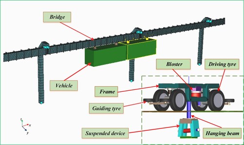
Table 1. DOFs of vehicle subsystem.
Table 2. Main natural vibration frequencies of the vehicle under normal load.
2.2. Bridge subsystem
2.2.1. Component modal synthesis
The component modal synthesis (CMS), as a high-efficiency solution methodology, is usually adopted for the vibration analysis of large-sized and complicated structures in the engineering field. Typically, Hurty [Citation32,Citation33] proposed a fixed-interface modal synthesis method in 1960, and Hou [Citation34] developed a free-interface modal synthesis method in 1969. Later, some scholars also further made some improvements on the abovementioned modal synthesis methods [Citation35–39]. The CMS method is also named as the modal synthesis method of branch structure, in which a large-scale and complex structure could be separated into a few substructures according to its structural characteristics; subsequently, the modes of each substructure could be obtained by the modal analysis, whose main low-order vibration modes would be extracted for the dynamic analysis; subsequently, all the substructures would be combined into a whole based on the interface constrain conditions. Due to the fact that only the main lower-order modes of the substructures are extracted, the DOFs of the entire large-scale structure are reduced tremendously, which can greatly enhance the calculation efficiency.
2.2.2. Modelling of the suspended monorail bridge
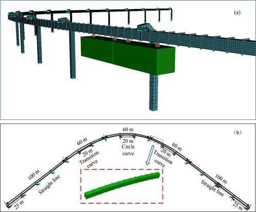
The suspended monorail bridge consists of the thin-walled box beams with an open bottom and the piers with an inverted ‘L’ shape and the constrain between them is the simply supported type. Based on its structural characteristics, the bridge could be divided into several substructures including the girders and the piers, and low-order modes of all substructures can be obtained based on modal analysis in ANSYS software; On this basis, the girders and piers can be combined into a whole bridge subsystem based the fixed interface modal synthesis method where the girders and piers are connected by the simply-support constrains. To obtain the bridge modes, a refined 3D FEM including the straight bridges with 25 m span and the curved bridges with 20 m span is built adopting the Shell181 element in ANSYS software, and it includes the girder, pier and connection, as presented in Figure . The simply-supported constraint is employed between the beam and pier and all pier bottoms are subjected to the fixed constraints. The material and geometric parameters of the bridge can be seen in the Appendix.
Figure 3. Suspended monorail train-curved bridge interaction model: (a) Train running through curved bridge (b) Sketch of simulation line.
To reveal the natural vibration features of the monorail bridge, Figure gives a few main modal shapes and corresponding vibration frequencies of the circle curved bridge. Simultaneously, Table gives the main vibration frequencies of the first 70 orders of the established bridge FEM.
Figure 4. Main modal shapes of the circle curved bridge.
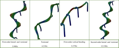
Table 3. Main modal of the bridge.
2.2.3. Solution method
Based on the structural dynamics theory, the motion equation of the bridge could be expressed as follow [Citation13]:
(1)
(1) Where M, C and K are the mass matrix, the damping matrix and the stiffness matrix, respectively; Fv(t) is the tire forces that are applied to the track surface.
The damping matrix of the bridge can be expressed with the Rayleigh-damping widely used as follow [Citation40]:
(2)
(2) Where a and b denote the constant coefficients of mass and damping matrixes, respectively.
Based on the modal superposition method (MSM), the elastic deformation of the monorail bridge is expressed as:
(3)
(3) where
,
,
,
; α and β represent the girder substructure and pier substructure, respectively; i and j denote the interior displacement coordinates and interface displacement coordinates, respectively.
By adopting the MSM, the vibration of the bridge could be written as uncoupled equations in the form of generalised coordinates. After the first coordinate conversion, the bridge motion equation could be act as:
(4)
(4) Where Mp, Cp and Kp denote matrices of the generalised mass, the generalised damping and the generalised stiffness, respectively.
These matrixes above can be obtained from the equations as follows:
(5)
(5)
(6)
(6)
(7)
(7)
(8)
(8)
The non-independent generalised displacement coordinates are included in the matrix p, which cannot be solved directly, so a second coordinate conversion is required.
The compatibility condition on the displacement of girders and piers is given as [Citation39]:
(9)
(9)
The compatibility condition on the force of the interface nodes is as follow:
(10)
(10)
According to the formula (3) and the compatibility displacement condition on the displacement of the girder and the pier, it can be obtained as follow:
(11)
(11) where
,
; α and β represent the girder substructure and pier substructure, respectively.
The generalised displacement coordinates on interface nodes can be expressed as:
(12)
(12) Where pI is the independent generalised displacement coordinates and pd is the non-independent generalised displacement coordinates.
The formula (11) can be expressed as:
(13)
(13) Where DI is the modal shape matrix for the independent generalised displacement coordinates and Dd is the modal shape matrix for the non-independent generalised displacement coordinates.
Consequently, p can be obtained as:
(14)
(14) Where S denotes the second coordinate conversion matrix; q is the independent generalised displacement coordinates and
.
The motion equation of the entire bridge subsystem includes the girders and piers could be written as:
(15)
(15) Where Mz, Cz and Kz represent the matrices of the mass, damping and stiffness after the second coordinate transformation, respectively.
(16)
(16)
(17)
(17)
(18)
(18)
(19)
(19)
After the second coordinate transformation, q will be the independent generalised displacement coordinates, and the generalised displacement coordinates of the flexible bridge can be obtained with the Park integral method [Citation41]. According to Equation (1), the vibrational responses of the bridge can be got.
2.3. Wheel-track contact model
In the existing study of the monorail VBI, a point-contact tire model with the linear stiffness was often used to model the wheel-track radial contact behaviour because of its simpleness [Citation23–26,Citation29,Citation30]; even if the point-contact model can reflect basic wheel-track interaction features to some extent, it may also cause a larger error of evaluating the wheel-track dynamic responses due to its great simplification. To more reasonably model the wheel-track mechanical behaviour of the monorail system, some scholars directly adopted the FIALA tire model that is a classic tire contact model used in road car because the rubber tire used in monorail system is similar to the tire in road car system [Citation31]; compared with the point-contact tire, the FIALA tire model could more comprehensively reflect the mechanical features of rubber tire, which can simulate the radial force, side force, longitudinal force, aligning torque, etc. It is worth pointing out that the values of the side force, longitudinal force, and aligning torque are related to the radial force in this FIALA model; thus, the reasonable modeling of the tire radial force is the key to accurately reflect the wheel-track contact behaviour.
In this work, to accurately model the wheel-track dynamic features, the FIALA tire model is improved based on the mechanical characteristics of the monorail tire where a nonlinear radial mechanical model of the monorail tire is adopted, whose radial stiffness and damp are determined by a mechanical experiment. Figure (a) presents the experimental set-up for a full-scale suspended monorail rubber tire test, and the detailed experimental introduction can be found in the literature [Citation28]. Figure (b) shows the radial static tire forces under the different radial static displacements.
Figure 5. The experiment set-up for a suspended monorail rubber tire [Citation28]: (a) experiment set-up; (b) Force-displacement curve of the tire obtained by the test.
![Figure 5. The experiment set-up for a suspended monorail rubber tire [Citation28]: (a) experiment set-up; (b) Force-displacement curve of the tire obtained by the test.](/cms/asset/94b3fd4f-ea36-4b1e-a182-7cf1bab6a843/nvsd_a_1918727_f0005_oc.jpg)
As presented in Figure (b), there is a nonlinear relation between radial tire force F and the deformation s of the tire center. The relation expression of F and s was obtained through a nonlinear fitting procedure [Citation28]:
(20)
(20)
Further, the nonlinear stiffness k(s) was also obtained by calculating the first derivative of the F(s) [Citation28]:
(21)
(21)
Additionally, the damping coefficient of the tire was also obtained by the dynamic test [Citation28], which is about 12.4 kN·s/m.
An improved mechanics formula for calculating tire radial force could be expressed as follows:
(22)
(22) Where kz denotes the nonlinear radial stiffness of the tire that is determined by the experiment, whose expression is shown in Equation (21). cz is radial damping of the tire; zw is the radial displacement of the driving tire; zr and zi are the vertical displacement of the bridge and track irregularity at the wheel-track contact point, respectively; vΔz represents the gradient of the tire deformation.
In this work, referring to the FIALA tire model [Citation42], the creep of the tire is defined as:
(23)
(23) Where Sx and Sy are the longitudinal creep and sideslip of the tire, respectively; w denote the rolling angular velocity of the tie; Re is the effective radius of the tire; v and u represent the velocities in longitudinal and lateral directions, respectively.
(24)
(24) Where s and s* denote the bounding points for longitudinal forces of the tire, respectively; Fz denote the tire radial force; μ is the friction coefficient in the sliding state of the tire.
The longitudinal force of tires could be expressed as follow:
(25)
(25) Where Sx and Sy are the longitudinal creep and sideslip of the tire, respectively; μ is the friction coefficient in the tire sliding state, μ = μ0 + (μ1 − μ0)s, μ0 and μ1 are the coefficient of static and kinetic friction, respectively.
(26)
(26) Where h and s′ denote middle parameters and bounding points for the forces of tires, respectively; FZ represents the tire radial force; cx is the longitudinal creep stiffness, cy is the cornering stiffness.
Tire side forces of the tire could be expressed as:
(27)
(27) Where FZ denotes the tire radial force; Sx and Sy are longitudinal creep and sideslip of the tire, respectively.
The aligning moment of the tire is as follow:
(28)
(28) Where FZ denotes the tire radial force; Rt is the toroidal radius of tire; Sy is longitudinal creep and sideslip of tire; h and s′ denote middle parameters and bounding points for the forces of the tire, respectively.
It is worth noting that the values of the longitudinal force Fx, side force Fy, and aligning torque Mz in Equations (25)–(28) are related to the radial force Fz, and the radial force Fz is calculated by the improved mechanics’ formula shown in Equation (20).
2.4. Modelling of train-curved bridge interaction
In this work, the coupled vibration analysis of the SMTCB is conducted based on a co-simulation method where a detailed train subsystem is built employing the software UM, and a curved bridge subsystem is built adopting the software ANSYS, whose modal information is also extracted to put into the UM software. The train and bridge are coupled in the UM software by an improved wheel-track contact model (IWTCM). The proposed approach has the following merits:
The bridge is established based on the component modal synthesis, and its main DOFs are extracted for the dynamic simulation. Thus, the total DOFs of the bridge are reduced tremendously, which greatly enhances the calculation efficiency.
An IWTCM is proposed and adopted for the simulation of the SMTCB, and its simulation parameters were obtained by the full-size experiment. The IWTCM considers more real radial contact relation of the monorail tire with nonlinear features, which can reflect the change of the tyre radial stiffness along with radial compression deformation, thus it can more reasonably model the interactive features between the monorail tire and the track.
This approach can allow for the accurate modeling of the vehicle subsystem with complicated components owing to the powerful modeling capacity of UM software.
3. Model validation
The accuracy and convergence of the CMS method highly dependent on the number of the extracted modes of the target structure. If the extracted modes are too many, the calculation cost would be greatly increased; if the extracted modes are not enough, the simulation results may have a large error. In most of the existing study [Citation30,Citation31], the convergence and accuracy of this method are discussed rarely, and it is also a lack of validation with the field test. In this section, taking the SMS as an example, the convergence and precision of the CMS method are comprehensively investigated. Referring to the specification [Citation43], the care frequencies of the vertical vibration of the suspended monorail bridge are below 20 Hz in the evaluation of time-history responses. Therefore, the bridge accelerations are filtered with a low-pass of 20 Hz in this work. The research results could provide some useful references for similar researches.
3.1. Convergence and accuracy analysis of the proposed model
Adopting the proposed model, the empty vehicle-straight bridge dynamic responses under different numbers of the extracted modes are analyzed and also compared with the experimental results. The adopted simulation parameters are presented in the Appendix. The bridge track irregularities were measured and obtained in Ref. [Citation27,Citation28]. Figure presents the comparison results of vehicle-straight bridge vibrational responses when the vehicle travels through the bridge at 40 km/h under empty load.
Figure 6. Vibrational response comparisons under different extracted modal orders of bridge: (a) Bridge vertical displacement; (b) Bridge vertical acceleration; (c) Car-body vertical acceleration; (d) Radial force of the driving tire.
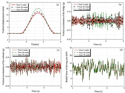
It could be seen from Figure , the number of extracted bridge modes has significant influences on the bridge acceleration and displacement, however, it presents small influences on the vehicle accelerations and radial force of the driving tire. The main reason may be that when the extracted modes are not enough, the bridge vibration at the higher frequency range would be missing, which causes a large error of the bridge acceleration and displacement. For the monorail vehicle, the track irregularity is the dominant factor influencing the carbody vibration, and the vibration and deformation of bridge have relatively smaller influences on the vehicle acceleration.
To further explore the effects of the extracted modal orders on the bridge vibration responses and determine the minimum extracted orders that ensure reliable and accuracy simulation results, Figure gives the accelerations and displacements of the straight bridge along with the extracted modal orders under different train running velocities (20, 40 and 60 km/h). The velocity of 60 km/h is the maximum design speed of the suspended monorail vehicle.
Figure 7. Vibrational responses of bridge with the extracted modal orders under different running velocities: (a) Bridge acceleration under 20 km/h; (b) Bridge displacement under 20 km/h; (c) Bridge acceleration under 40 km/h; (d) Bridge displacement under 40 km/h; (e) Bridge acceleration under 60 km/h; (e) Bridge displacement under 60 km/h.
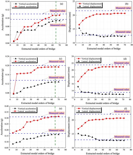
As presented in Figure , under different train running velocities, the bridge vibration responses would be gradually close to the measured data with an increase of the extracted modal order. Noteworthily, when the extracted modal order is lower than 10, the accelerations and displacements of the bridge will have a big error compared with the measured values, showing that too few extracted modes of the bridge may cause wrong simulation results. However, it could also be found that when the extracted modal order is more than 65, all dynamic responses under different vehicle running velocities change slightly and are also consistent with the measured results. Therefore, for ensuring the accuracy of the bridge vibrational responses subjected to low-pass filter of 20 Hz, the extracted modal orders of the bridge are recommended to be more than 65.
3.2. Dynamic response comparison by simulation and test
To further check the effectiveness of the developed model, the vehicle-bridge vibrational responses from numerical analysis and field tests are compared when an empty vehicle runs on a curved line with a horizontal radius of 170 m at 40 km/h, as shown in Figure . In the field tests, the accelerations located at the car-body floor and the displacements and accelerations of 1/2 span beam are measured; the detailed test method and measuring position arrangements could be found in the literature [Citation27]. In this simulation, the extracted modal order is 65, and the locations of the simulation points are consistent with those of the test points.
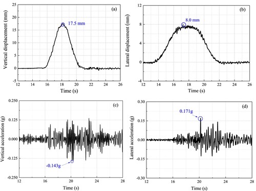
Figure 8. Vibrational response comparisons of the vehicle and circular curved bridge: (a) Bridge vertical displacement;(b) bridge lateral displacement;(c) Bridge vertical acceleration; (d) Bridge lateral acceleration; (e) Car-body vertical acceleration; (f) Car-body lateral acceleration.
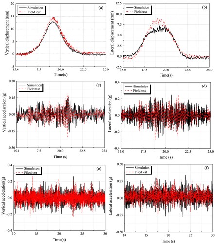
It could be seen from Figure , the modeling results are well consistent with the test data, validating the reliability of the proposed model. Moreover, it can also be found that compared with the conventional railway system, the monorail vehicle and bridge have stronger vibration levels and the monorail bridge has larger deformation under train load. It is meaningful to elaborately carry out an investigation on the interactive feature of the SMTCB.
4. Effect of the nonlinear wheel-track contact relation
To research the effects of wheel-track contact relation on the vehicle-bridge interaction and reveal the significance of adopting the improved wheel-track contact model (IWTCM), the vehicle-bridge vibration responses under the IWTCM are compared with those under the traditional FIALA tire model used in a road car. The main discrepancy between the two tire models is that the traditional FIALA tire model usually considers a linear radial stiffness, however, the IWTCM considers a nonlinear radial stiffness that is obtained by a full-size experiment. Some introduction about the tire models could be found in section 2.3. Firstly, Figure reports the main simulation results under the above two tire models while the train goes through the straight bridge. In this simulation, the vehicle is considered to be under normal load condition that denotes a normal number of passengers, and the main simulation parameters could be seen in the Appendix; the vehicle velocity is 40 km/h; the linear radial stiffness with 3kN/mm is considered for the traditional FIALA tire model. It should be pointed out that the 3 kN/mm is only taken as an example to reveal the differences between the two models in this section.
Figure 9. Dynamic response comparisons between the IWTCM and FIALA tire models: (a) Radial force of driving tires; (b) Vertical acceleration of the bogie center; (c) Car-body vertical acceleration; (d) Car-body lateral acceleration; (e) Bridge vertical acceleration; (f) Bridge lateral acceleration.
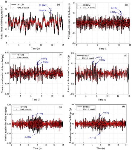
As can be seen in Figure (a), the amplitudes of the tire radial forces under the IWTCM are larger than those under the traditional FIALA tire model by about 3.15 kN. Further, as demonstrated in Figure (b)–(f), compared with those under the traditional FIALA tire model, the vertical acceleration of the bogie under the IWTCM increases by around 25.5%; the car-body vertical acceleration and lateral acceleration under the IWTCM increase by around 24.6% and 26.9%, respectively; the vertical acceleration and lateral acceleration of the bridge under the IWTCM also add by around 20.0% and 27.6%, respectively. It is shown that the wheel-track contact relation has significant effects on the coupled vehicle-bridge vibration responses. When the driving tire has the nonlinear vertical stiffness, the wheel-track dynamic interaction is obviously stronger and the vehicle-bridge coupling vibration responses would be also larger.
To further compare the discrepancies between the abovementioned two tire models, the frequency spectra of the tire force, vehicle acceleration and bridge acceleration are presented, as shown in Figure .
Figure 10. Frequency spectrum comparisons of dynamic responses between IWTCM and FIALA tire models with linear stiffness: (a) Radial force of driving tire; (b) Bogie vertical acceleration; (c) Car-body vertical acceleration; (d) Bridge vertical acceleration.
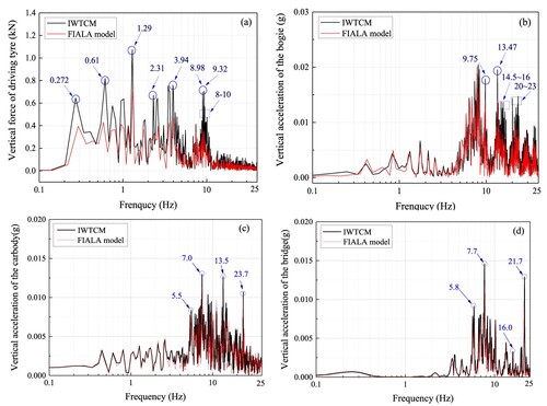
By observing Figure (a), the frequency spectrum amplitudes of the driving tire force under the IWTCM are obviously larger than those under the FIALA tire model with linear stiffness in the entire frequency domain range, indicating that the nonlinear wheel-track vertical stiffness significantly influences the wheel-track vertical interaction force. As presented in Figure (b), under the IWTCM, the frequency spectrum amplitudes of the bogie acceleration are bigger above 7.35 Hz; however, the frequency spectrum amplitudes of the bogie vertical accelerations between the abovementioned two tire model have relatively small discrepancies at low-frequency range.
As presented in Figure (c) and (d), under the IWTCM, the frequency spectrum amplitudes of the vehicle acceleration are obviously bigger within 5.5–23.7 Hz and the frequency spectrum amplitudes of the bridge acceleration are larger in the entire frequency domain range; additionally, it could be found that the frequency spectrum amplitudes of the vehicle and bridge accelerations between the abovementioned two tire models have relatively smaller discrepancies at low-frequency range (below 5.5 Hz). These research results show that the nonlinear wheel-track vertical stiffness mainly increases the high-frequency vibration of the vehicle and bridge, however, it has a small influence on their low-frequency vibration.
Besides, to further compared the differences between IWTCM and the traditional Fiala tyre model, the dynamic responses obtained by the traditional Fiala tyre model with different radial stiffness are compared with those obtained by the IWTCM, as listed in Table .
Table 4. Comparison results between IWTCM and the Fiala tyre model with different radial stiffness.
As listed in Table , when the radial stiffness is considered to be 3, 5, and 7 MN/m, respectively, the dynamic responses obtained by the traditional FIALA model present some obvious differences compared with those obtained by the IWTCM. With the increase of the radial stiffness, all dynamic responses obtained by the traditional FIALA model would significantly increase. It is clear that the choice of the radial stiffness of the traditional FIALA model has prominent effects on the evaluation results of the monorail vehicle-bridge vibrational responses.
It is worth pointing out that the radial deformation of the rubber tyre would continually change due to the effects of random track irregularity. Generally, the radial stiffness of the rubber tyre under different radial deformation would be obviously different, which usually increases with an increase of the radial compression deformation. The traditional FIALA tyre model with a constant stiffness means that the tyre radial stiffness always keeps the same under any compression deformation, thus it cannot fully reflect the change of the tyre radial stiffness under different compression deformation. In this regard, the IWTCM considers a real nonlinear radial contact stiffness of suspended monorail tyre, thus it can well reflect the change of the tyre radial stiffness under different compression deformation. Therefore, to better evaluate the monorail vehicle-bridge vibration responses, adopting the IWTCM would be more reasonable in modeling suspended monorail vehicle-bridge interaction.
5. Coupled vibration analysis between vehicle and curved bridge
The suspended monorail bridge includes many small radius curves in actual operation lines. To investigate the coupled vibration features between the vehicle and small curved bridge, a comprehensive dynamic analysis for the SMTCB is conducted. In this simulation, considering that the monorail train would often travel through a small curved line under actual operation condition, the horizontal radius of the circular curved bridge is considered to be 100 m, and the bridge route can be seen in Figure (b); the vehicle is considered to be under normal load; the vehicle velocity is 30 km/h.
When the vehicle runs through a curved bridge, the mechanical characteristic of the driving and guiding tires of the bogie are shown in Figure . PgL1∼PgL4 and PgR1∼PgR4 denote the radial forces of left and right guiding tires of the wheelsets 1∼4, respectively; FCL1∼FCL4 and FCR1∼FCR4 denote the side forces of left and right driving tires of the wheelsets 1∼4, respectively; MCL1∼MCL4 and MCR1∼MCR4 denote the aligning torque of left and right driving tires of the wheelsets 1∼4, respectively; Lg denotes the half of guide tire wheelbase, Lt denotes the half of driving tire wheelbase.
Figure 11. The mechanical features of bogie when passing through the curved bridge.
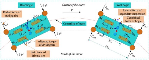
Taking the front bogie as an example, the balance equation of yawing motion moment of bogie could be expressed as follows:
(29)
(29)
5.1. Vehicle-bridge vibration responses
Firstly, to reveal the mechanical characteristic of each tire of the vehicle running through the curved bridges, Figure presents the wheel-track forces of the driving tire and guiding tire.
Figure 12. Dynamic responses of driving and guiding tire forces on the front bogie: (a) Radial force; (b) Aligning torque; (c) Side force; (d) Guiding force.
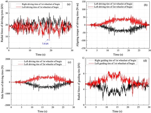
As seen from Figure (a), when the vehicle goes through the curved bridge, the radial force of the left driving tire located at the outside of the curve is reduced, while the radial force of the right driving tire located at the inside of the curve is significantly increased. It could be found that the minimum value of the radial force of the left driving tire is around 7.8 kN under 30 km/h; if the vehicle velocity increases, the radial force of the left driving tire may turn to be 0 due to larger centrifugal force of the train, which means that the left driving tire may leave the track at some moments; meanwhile, the radial force of the right driving tires would significantly increase, which may accelerate the wear and damage of tire, as well as be harmful to the vehicle dynamic performance.
As demonstrated in Figure (b) and (c), when the vehicle goes through the curved bridge, the side forces and the aligning torque of the front and rear driving tires of the bogie is in the opposite direction, and their values are very small. Generally, the side forces and the aligning moments of the rubber tire increase with an increase of the slip angle and camber of the tire. In comparison to the road car, the suspended monorail line has larger curve radius, thus the slip angle and camber of the monorail tire would be smaller; simultaneously, the slip angle and camber of the monorail tire would be further decreased with the help of guiding tires. The above reasons can account for the small side force and aligning torque of the monorail driving tire. To sum up, the radial forces of driving tires of monorail vehicles running on the curve line should be paid more attention to. Additionally, it can be seen from Figure (d), the radial force of the left guiding tire gradually increases, while the radial force of the right guiding tire gradually decreases, which mainly is caused by inertia force.
Figures and present the vehicle-bridge vibration responses when the vehicle passes through the curve bridges.
Figure 13. Vibrational responses of vehicle: (a) Rolling angular acceleration; (b) Pitching angular acceleration; (c) Vertical acceleration; (d) Lateral acceleration.
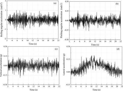
Figure 14. Dynamic responses of the circle curved bridge: (a) Vertical displacement; (b) Lateral displacement; (c) Vertical acceleration; (d) Lateral acceleration.
As shown in Figure (a) and (b), the rolling and pitching angular acceleration peaks of the vehicle are 1.1 and 0.26 rad/s2, respectively. It is shown that the rolling vibration of the monorail vehicle is significantly stronger than its pitching vibration. As seen in Figure (c) and (d), the vertical and lateral accelerations of the monorail vehicle are bigger compared with the traditional railway vehicle, showing that the vibration of running monorail vehicles is stronger. It could be also found that when the vehicle runs from the straight to the curve, the car-body vertical acceleration has a small change, however, the car-body lateral acceleration would increase due to the influences of the line curvature change and the car-body centrifugal force.
By observing Figure , the vertical and lateral displacements of the circular curve bridge are 17.5 mm and 8.0 mm, respectively, showing the monorail bridge produces a large deformation under the trainload. The vertical and lateral accelerations of the circular curve bridge are 0.143 and 0.171 g, respectively; it could be seen that the lateral vibration of the bridge is stronger than its vertical vibration, which may be due to its special structure features.
By the above research, it could be known that when the suspended monorail vehicle runs on the curved bridge, the monorail vehicle would produce larger vibration; especially, the driving tire of the bogie would have an obvious unbalance loading, and this may sharply decrease the tire life, thus influencing the vehicle dynamic performances.
5.2. Influences of key parameters
The lateral distance of the driving tires (the distance between two tires of each wheelset) and the secondary suspension parameters, as the key design parameters, have important influences on the curve negotiation performances of monorail vehicles. To reveal their influences, Tables summarised the vehicle-bridge vibration responses under different secondary suspension parameters and lateral distances of the driving tires. Simultaneously, regarding each maximum dynamic index (listed in Tables ) as the reference value, the normalised vibrational responses also are presented in Figure .
Figure 15. Normalised dynamic responses under different influence factors: (a) Lateral distance of the driving tires; (b) Vertical stiffness of the secondary suspension (c) Vertical damping of the secondary suspension.
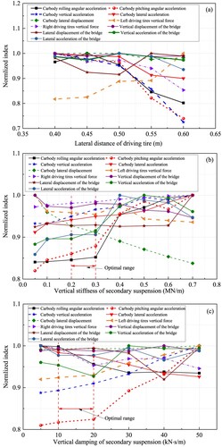
Table 5. The vehicle-bridge vibration responses under different lateral distances of the driving tires.
Table 6. The vehicle-bridge vibration responses under different vertical stiffness of the secondary suspension.
Table 7. The vehicle-bridge vibration responses under different vertical damping of the secondary suspension.
As shown in Table and Figure (a), with an addition of the lateral distance of driving tires, the car-body accelerations and lateral displacement gradually decrease, and the unbalanced loading of left and right driving tires also reduces obviously, indicating that increasing the lateral distance of driving tires could effectively improve the vehicle dynamic performances and wheel-track system. Besides, it can be found that the lateral distance of driving tires has a smaller effects on the bridge vibrational responses. Therefore, under the premise of meeting the design and installation requirements, the lateral distance of the driving tires is suggested to be designed to be as large as possible. Based on current structure sizes of bogie and box beam, the lateral distance of the driving tires is recommended to be 0.6 m.
By observing Table and Figure (b), with a decrease of the vertical stiffness of secondary suspension, the vehicle and bridge accelerations gradually deduce, however, the lateral displacement of the vehicle would rise. This shows that decreasing the secondary suspension vertical stiffness could well suppress the vehicle vibration, but it could also increase the car-body lateral motion amplitude. Besides, it can be also found that the secondary suspension vertical stiffness has a smaller influence on bridge displacement. From the angle of effectively controlling the vehicle-bridge vibration and car-body lateral displacement, the secondary suspension vertical stiffness is recommended to be 0.2–0.3 MN/m.
As presented in Table and Figure (c), with an increase of secondary suspension vertical damping, the vertical acceleration and pitching angular acceleration of the carbody would increase, while its lateral acceleration and the rolling angular acceleration would decrease. The main reason may be that increasing the secondary suspension vertical damping aggravates the car-body pitching motion, thus intensifying the car-body vertical vibration. Similarly, increasing the secondary suspension vertical damping suppresses the car-body roll motion, thus improving the car-body lateral vibration. To simultaneously consider the vertical and lateral vibrations of the monorail vehicle, the secondary suspension vertical damping is recommended between 10 and 20 kN·s/m.
6. Conclusion
In this article, a high-efficiency dynamic model has been built to investigate the coupled vibration features of suspended monorail train and curved bridge (SMTCB). For this purpose, firstly, the train dynamic model and bridge model have been established based on the theory of multi-body dynamics and finite element method, respectively. Meanswhile, an improved wheel-track contact model (IWTCM) has been proposed based on the traditional FIALA tire model, which considers nonlinear radial stiffness. The train and bridge subsystems are coupled by the IWTCM where the main modes of bridge are extracted for calculating its vibration responses. Then, the effects of the extracted bridge modal orders on vehicle-bridge vibrational responses have been discussed in detail and some obvious discrepancies have been also found by comparing the vehicle-bridge response results between the traditional FIALA tire model and the IWTCM. Finally, the coupled vibration features of the SMTCB have been studied comprehensively and a few key parameters have been also chosen reasonably. The main conclusions are as follows:
A highly-efficient coupled dynamic model of the SMTCB is developed adopting a co-simulation method, which is validated by the field test. The developed model can make an accurate and highly-efficient prediction for the monorail vehicle-curved bridge coupling vibration responses.
The mode order extracted of the bridge has significant influences on the simulation results of vehicle-bridge dynamic responses, especially the acceleration and displacement of the bridge. For ensuring the accuracy of the bridge vibrational responses subjected to low-pass filter of 20 Hz, the mode orders extracted of the bridge are suggested to be more than 65.
The wheel-track relation has important influences on the monorail vehicle-bridge vibrational responses in time and frequency domains. Compared with the traditional FIALA tire model with a linear radial stiffness, adopting the improved wheel-track contact model with the nonlinear radial stiffness could more reasonably model the wheel-track contact behaviour.
When the suspended monorail vehicle travels through the curve line, the left and right driving tire of the bogie would have an obvious unbalance loading and the monorail vehicle would produce larger vibration. To ensure a good vehicle dynamic performance, it is recommended that the reasonable ranges of secondary suspension vertical stiffness and damping are 0.2 MN/m and 10–20 kN·s/m, respectively; the lateral distance of the driving tires should be designed to be as large as possible under the precondition of satisfying the design and installation requirements.
Disclosure statement
No potential conflict of interest was reported by the author(s).
Additional information
Funding
References
- Grava S. Urban transportation systems, choices for communities. New York: McGraw-Hill; 2003.
- Zhai WM, Zhao CF. Frontiers and challenges of sciences and technologies in modern railway engineering. J Southwest Jiaotong Univ. 2016;51(2):209–226.
- Boehm E, Frisch H. The new operating system of the H-train in dortmun. Verkehr Technik. 1994;47(10):465–470.
- Rahier HW, Scharf P. Sicherheitstechnische prüfung derfahrerlosen kabinenbahn des flugha-fens duesseldorf. Signal Draht. 2002;94(10):20–22.
- He Q, Cai C, Zhu S, et al. Field measurement of the dynamic responses of a suspended monorail train–bridge system. P I Mech Eng F J Rai. 2020;234(10):1093–1108.
- Zhai WM, Han Z, Chen Z, et al. Train–track–bridge dynamic interaction: a state-of-the-art review. Veh Syst Dyn. 2019;57(7):984–1027.
- Yang YB, Lin CW. Vehicle-bridge interaction dynamics and potential applications. J Sound Vib. 2005;284(1-2):205–226.
- Zhai WM, Xia H, Cai CB, et al. High-speed train–track–bridge dynamic interactions – part I: theoretical model and numerical simulation. Int J Rail Transp. 2013;1:3–24.
- Zhu Z, Zhang L, Gong W, et al. An efficient hybrid method for dynamic interaction of train–track–bridge coupled system. Can J Civ Eng. 2020;47(9):1084–1093.
- Cantero D, Arvidsson T, Obrien E, et al. Train-track-bridge modelling and review of parameters. Struct Infrastruct E. 2015;12(9):1051–1064.
- Dimitrakopoulos EG, Zeng Q. A three-dimensional dynamic analysis scheme for the interaction between trains and curved railway bridges. Comput Struct. 2015;149(3):43–60.
- Tanabe M, Sogabe M, Wakui H, et al. Exact time integration for dynamic interaction of high-speed train and railway structure including derailment during an earthquake. J Comput Nonlin Dyn. 2016;11(3):031004.
- Zhang N, Xia H. Dynamic analysis of coupled vehicle–bridge system based on inter-system iteration method. Comput Struct. 2013;114(1):26–34.
- Montenegro PA, Neves SGM, Calçada R, et al. Wheel–rail contact formulation for analyzing the lateral train–structure dynamic interaction. Comput Struct. 2015;152(3):200–214.
- Dinh VN, Kim KD, Warnitchai P. Dynamic analysis of three-dimensional bridge-high-speed train inter-actions using a wheel-rail contact model. Eng Struct. 2009;31(12):3090–3106.
- Antolín P, Zhang N, Goicolea JM, et al. Consideration of nonlinear wheel–rail contact forces for dynamic vehicle–bridge interaction in high-speed railways. J Sound Vib. 2013;332(5):1231–1251.
- Iwnicki SD, Brickle BV. The dynamic behaviour of a rail locomotive with solid rubber tyres and flanged steel wheels. Veh Syst Dyn. 1988;17(1):173–185.
- Xia H, Zhang N. Dynamic analysis of railway bridge under high-speed trains. Comput Struct. 2005;83(23-24):1891–1901.
- Montenegro PA, Calçada R, Vila Pouca N, et al. Running safety assessment of trains moving over bridges subjected to moderate earthquake. Earthq Eng Struct D. 2016;45(3):483–504.
- Ling L, Dhanasekar M, Thambiratnam DP. Dynamic response of the train–track–bridge system subjected to derailment impacts. Veh Syst Dyn. 2018;56(9):638–657.
- Matin A, Elias S, Matsagar V. Distributed multiple tuned mass dampers for seismic response control in bridges. Proc Inst Civil Eng Struct Build. 2019;173(3):1–18.
- Chen Z, Han Z, Zhai W, et al. TMD design for seismic vibration control of high-pier bridges in Sichuan–Tibet Railway and its influence on running trains. Veh Syst Dyn. 2019;57(2):207–225.
- Naeimi M, Tatari M, Esmaeilzadeh A, et al. Dynamic interaction of the monorail–bridge system using a combined finite element multibody-based model. Proc Inst Mech Eng. 2015;229(2):132–151.
- Leng H, Ren L, Ji Y, et al. Radial adjustment mechanism of a newly designed coupled-bogie for the straddle-type monorail vehicle. Veh Syst Dyn. 2020;58(6):1407–1427.
- Lee CH, Kawatani M, Kim CW, et al. Dynamic response of a monorail steel bridge under a moving train. J Sound Vib. 2006;294(3):562–579.
- Zhou J, Du Z, Yang Z, et al. Dynamic parameters optimization of straddle-type monorail vehicles based multiobjective collaborative optimization algorithm. Veh Syst Dyn. 2020;58(2):357–376.
- Cai C, He Q, Zhu S, et al. Dynamic interaction of suspension-type monorail vehicle and bridge: numerical simulation and experiment. Mech Syst Signal Pr. 2019;118(3):388–407.
- He Q, Cai C, Zhu S, et al. An improved dynamic model of suspended monorail train-bridge system considering a tyre model with patch contact. Mech Syst Signal Pr. 2020;144(10):106865.
- He Q, Cai C, Zhu S, et al. Key parameter selection of suspended monorail system based on vehicle–bridge dynamical interaction analysis. Veh Syst Dyn. 2019;58(2):339–356.
- Bao Y, Li Y, Ding J. A case study of dynamic response analysis and safety assessment for a suspended monorail system. Int J Env Res Pub He. 2016;13(11):1121.
- Jiang Y, Wu P, Zeng J. Researches on the resonance of a new type of suspended monorail vehicle-bridge coupling system based on modal analysis and rigid-flexible coupling dynamics. Veh Syst Dyn. 2021;59(9):135–154.
- Hurty WC. Vibrations of structural systems by component mode synthesis. J Eng Mech Divis. 1960;86(4):51–70.
- Hurty WC. Dynamic analysis of structural systems using component modes. AIAA J. 1965;3(4):678–685.
- Hou SN. Review of modal synthesis techniques and new approach. Shock Vib Bull. 1969;40(9):25–399.
- Zhang W, Lv S, Ni Y. Parametric aeroelastic modeling based on component modal synthesis and stability analysis for horizontally folding wing with hinge joints. Nonlinear Dyn. 2018;92(2):1–11.
- Zucc S. On the dual Craig-Bampton method for the forced response of structures with contact interfaces. Nonlinear Dyn. 2017;87(11):2445–2455.
- Craig RR, Bampton CC. Coupling of substructures for dynamic analyses. AIAA J. 1968;6(7):1313–1319.
- Lou M, Ghobarah A, Aziz TS. A modal synthesis method for dynamic substructuring. Eur J Mech A Solids. 1993;12(12):403–416.
- Suarez LE, Singh MP. Modal synthesis method for general dynamic systems. J Eng Mech. 1992;118(7):1488–1503.
- Agabein ME. The effect of various damping assumptions on the dynamic response of structures. Bull Int Inst Seismol Earthq Eng. 1971;8(1):217–236.
- Park KC. An improved stiffly stable method for direct integration of nonlinear structural dynamic equations. Int J Appl Mech. 1975;42(6):464–470.
- Fiala E. Seitenkrafte am Rollenden Luftreifen. V.d.I. 1954;96:973–979.
- DBJ51/T 099. Standard for design of suspended monorail transit. Chengdu: Southwest Jiaotong University Press, 2018. (in Chinese).
Appendix
Table A1. Main parameter of the vehicle and the bridge.