
ABSTRACT
The location of covert graves is an important but challenging part of missing persons investigations. Although traditional search techniques, such as foot searches and cadaver dogs, have proved successful, the incorporation of higher technology methods, such as geophysical techniques, can be used to increase the chances of locating covert graves. This article will present a field method for the use of two geophysical techniques, including ground penetrating radar and electrical resistivity tomography, which can successfully locate covert graves in an Australian environment. If the soil and climate conditions permit, this technical protocol can be applied to other clandestine grave search sites as well. Ultimately, by increasing chances of locating the covert grave, and by extension the missing person, a successful judicial outcome can be achieved and highly sought after answers can be provided to the family.
Introduction
Currently, in Australia, there are over 2,600 long-term missing individuals (classified as those missing for three months or more), some of which can be assumed to be buried in covert (or clandestine) graves. From an offender’s perspective, burying their victim is advantageous because unmarked graves, by design, are difficult to findCitation1,Citation2. Being able to locate these burials is important, both for a successful judicial outcomeCitation3,Citation4, as well as for the victims’ families, as they may begin the grief processCitation5,Citation6.
The task of locating these covert burials falls within the remit of a police detective, or a team of officers/detectives, however specialist services, such as a forensic anthropologist or archaeologist, and occasionally a geophysicist, may be called upon. In a missing persons investigation where the individual is presumed dead and likely buried in a covert grave, an investigatory plan would be put together to search for them. This decision is made by a detective (or a team) based on compelling evidence, such as a witness statement, admissions made by the suspected offender, evidence from phone records or CCTV, as well as a suspect’s vehicle kilometres (or GPS) that suggest that they have recently attended an area that would allow for a covert burial (i.e. the bush). Search techniques vary from low-tech methods such as foot or pedestrian searchesCitation7,Citation8, and cadaver dogsCitation8,Citation9, to more technologically advanced methods such as satellite imagingCitation10, aerialCitation11 photography, light detection and ranging (LiDAR)Citation12,Citation13, drones and other Unmanned Aerial Vehicles (UAVs)Citation14–18, and near surface geophysical surveysCitation13,Citation19,Citation20. The latter, which are all considered remote sensing methods, are particularly beneficial because they image the subsurface quickly and non-invasively and allow investigators to be more sure about the location of a potential grave, as well as the grave’s dimensions, before undertaking a time-consuming and destructive excavation. Despite these benefits, their applicability has not yet been fully exploited by investigative agencies in Australia.
The purpose of this article is to present a technical protocol for using ground penetrating radar (GPR) and electrical resistivity tomography (ERT) when locating missing persons buried in covert graves. Although the survey parameters guiding a geophysical investigation will depend on the site, the nature of the suspected burial, and the soil conditions, this article will present a field method that can successfully detect graves. This article is not meant to act as a standardized guide, nor as a review of the use of GPR and ERT for grave detection, as these have both been previously done in Donnelly and HarrisonCitation21 and Berezowski et al.Citation19, respectively.
Background
Covert burials as a means of body deposition
A covert grave is defined as a hidden or illegal burial containing human remainsCitation22. Covert burials are generally only 0.5 m-1 m deepCitation23, often dug in discrete areas, in haste with hands or a shovel, and may be irregular in shapeCitation24. The main goal of a clandestine grave is detection (and prosecution) avoidanceCitation13. However, forensic anthropological practice demonstrates that clandestine graves often exhibit certain site and surface cues (referred to here as burial site logistics and surface-level changes) that, if present, can indicate buried human remainsCitation12. Burial site logistics (see ) are macro-level decisions made by the offender when choosing a location to bury their victim. These decisions are made out of convenience and expediency, as transporting a deceased individual is difficult, as well as to avoid apprehension. Subsequently, the act of creating the grave leaves micro-level surface changes (see ). When conducting a search for the grave, the search team will take into account the burial site logistics as well as the surface-level to aid in its discovery.
Table 1. Burial site logistics and surface-level changes that are taken into consideration when searching for covert burials.
Ground penetrating radar (GPR)
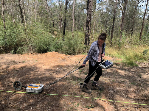
GPR is the most commonly used geophysical technique for clandestine grave detection because it produces high-resolution data in a relatively short amount of timeCitation19. A typical GPR system consists of a control unit, transmitting and receiving antennae, and a monitor that displays and records real-time data. GPR systems can be operated in many different ways, including being attached to a handle and pulled (shown in ), placed on a cart and pushed like a lawnmower, driven by a vehicle, and attached to a boat (known as water penetrating radar).
Figure 1. Mala X330 GPR in use. The transmitting and receiving antennae are inside the grey Mala box, with the GPR wheel at the back, and an extendable pole at the front. The monitor is used to set the survey parameters and can also display real-time data as the survey is progressing. This is useful to check that the wheel is tracking distance correctly.
GPR works best on flat sites with few surface obstructions, in sandy soils, fresh water, or through anthropogenic materials such as bitumen or concreteCitation27. Although GPR can directly detect grave materials, such as a decomposing bodyCitation28, skeletal remains (very rarely)Citation29, material evidence within the grave (i.e. weapons)Citation30, or materials used to wrap a body (for example, a tarp)Citation24,Citation31,Citation32, it is the soil disturbance resulting from digging and refilling the grave that is most often detectedCitation33. A GPR survey cannot definitively validate the presence of human remains (this can only be done with excavationCitation12), but can assess an area important to a missing persons investigation for potential gravesites. Once the survey is complete, a list of prioritized areas to excavate can be made and given to an excavation team.
GPR works by emitting electromagnetic waves into the ground (from the transmitting antenna), which are then reflected back to the receiving antenna as they encounter subsurface features with varying electrical propertiesCitation19,Citation34. These reflections are recorded as one-dimensional (1D) traces, and then automatically displayed as a 2D profile on the monitorCitation19. The electrical properties of subsurface materials (specifically their dielectric permittivity, defined as the degree of polarization that a material experiences while being exposed to an external electrical fieldCitation35), are dictated by material composition, water content, and porosityCitation19. The greater the contrast in dielectric permittivity between subsurface materials, the higher the resulting amplitude of the GPR response. When using GPR to locate covert burials, the anomaly created by the infilling of the grave with disturbed soil rarely has an obviously large contrast from undisturbed soil and so careful interpretation of the data is required. The receiving antenna also measures the signal return time, and this coupled with an estimation of the velocity properties of the subsurfaceCitation34,Citation36 allows for an experienced practitioner to estimate the depth of any subsurface features. This is known as a conversion of time to depth, and can be done accurately using hyperbola fitting, however, using a value of 0.1 m/ns provides a rough estimate in most conditions.
Important parameters necessary for a successful GPR survey include selecting antennae frequency, trace increment, and line spacing. Firstly, choosing the correct antennae frequency, which can range from 50 MHz to 2000MHzCitation36,Citation37, is important as it will dictate how deep the electromagnetic waves can penetrate, as well as the resolution of the dataCitation28. A lower frequency antenna can provide greater depth penetration; however, the resulting resolution will be low. Inversely, a higher frequency antenna can provide higher resolution, but may not penetrate as deepCitation28,Citation30,Citation36. To achieve both acceptable depth penetration and resolution, forensic surveys generally use antennae frequencies that range from 250 to 900MHzCitation33,Citation38, with SchultzCitation28,Citation30 stating that 500 MHz provides the best results. The recent availability of multi-frequency antennae, allows for both great depth penetration and high resolution dataCitation39. Regardless of the antenna frequency being used, depth penetration may be limited by conductive materialsCitation39,Citation40 such as clay rich and high saline soilsCitation27.
Next, choosing an appropriate trace/line increment (distance between each electromagnetic wave reflection) will increase the likelihood of locating anomalies that are consistent with a covert burial. Literature on hypothetical or synthetic GPR modelling that specifically focuses on human burial detection has found that the trace increment should be less than 0.10 m 23,Citation41. Notable experimental studies between 2008 and 2020, conducted by Pringle and colleaguesCitation23,Citation24,Citation31,Citation32, have generally replicated this parameter, by using 0.10 m, 0.05 m, and 0.025 m trace increments, however, three of the studies also included a survey with a 0.20 m trace increment. Depending on the size of the site and the number of GPR lines that will be collected, a trace increment between 0.10 m and 0.025 m should be used. This optimizes the balance between having a small enough trace increment to visualize the grave related anomalies, as well as the size of the resulting data files. Finally, to maximize target location, line spacing (the distance between each GPR line) should be no more than half of the shortest axisCitation19, which in the context of human burials should be no more than 0.5 m, however, a line spacing between 0.2 m to 0.5 m is appropriate. Again, this provides an acceptable balance between the number of GPR lines collected (more lines equates to more time on scene and more time subsequently processing each line) and maximizing the chances of visualizing the covert grave.
Electrical resistivity tomography (ERT)
Although not as commonly used as GPR in a forensic capacity, ERT is a useful geophysical technique to locate unmarked graves. Like GPR, it cannot confirm the presence of an internment, but can identify likely locations for excavation. ERT measures differences in the ground’s electrical properties, with highly disturbed areas (like graves) showing anomalous resistivity values compared to the surrounding/background soilCitation34. More specifically, an electrical current is run between two current (injects electrical current) and two potential (measures potential difference) electrodes in varying formations and spacings, that provides information about the resistivity of the subsurface at a variety of depthsCitation42. The resistivity of the subsurface is controlled by its composition, porosity, fluid saturation, and fluid chemistryCitation43, all of which are affected by the creation of a covert burial, due to the soil disturbance and the decomposition fluids. ERT data can be presented in 2D, 3D, or 4D, and requires specialized training to process and interpret.
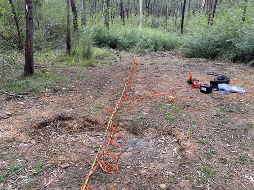
An ERT survey involves the use of multiple metal electrodes/stakes placed in the ground (depending on the manufacturer, the number of stakes varies), equidistant and across the mid-point of the area of interest (see for a fully set up ERT line). The length of an ERT line and the electrode configuration will dictate the maximum depth that can be achieved, with the total penetration being approximately 20% of the total line lengthCitation34. Other important survey parameters include the electrode spacing, as well as the electrode configuration (or array). Electrode spacing (space between the electrodes) controls the resolution of the resulting data, with the minimum spacing being equal to the maximum resolutionCitation19. To visualize grave-related subsurface anomalies, an electrode spacing of no more than 0.5 m should be used, however, optimal electrode spacing is < 0.25 m. As for electrode configuration, the relative placement of the current and potential electrodes will dictate the data resolution, sensitivity (to the target), and signal-to-noise ratio (a high signal-to-noise ratio will produce a reliable high-resolution image)Citation42,Citation44. Common configurations for covert burial detection include Wenner and Dipole–Dipole, however, LokeCitation42 provides a list of the additional electrode configurations. Research conducted by Cavalcanti et al.Citation45 and Doro et al.Citation46 demonstrated that while both show similar sensitivities in the shallow subsurface, the Dipole-Dipole array shows better sensitivity to the heterogeneity of the graves and the Wenner arrays show better resolution of the lateral boundaries and better vertical resolution. Time permitting, ERT data should be collected using multiple arrays to optimize the observability of the covert grave.
Figure 2. Fully set up ERT line, using a ZZ FlashRes64. The ERT line above is 16 m with a 0.25 m electrode spacing. The two orange 32 multi-core cables, which pass the electrical current, are attached to each of the electrodes and then attached to the ERT machine in the middle of the line. Power is obtained from a car battery with the ZZ software being run off a tablet.
ERT can work well in any type of terrain and is particularly useful in areas where GPR is less effective, such as clay-rich and high-saline soils, for sites where additional depth penetration is required, or areas with large surface and subsurface obstructionsCitation34,Citation37,Citation43. Experimental research has shown that an ERT survey should be undertaken prior to any sort of excavations or soil disturbances, such as those associated with validating metal detector surveys, as these can create false grave like features in the dataCitation47 (this would be the same for GPR as well). Another significant downside to ERT is its greater set up and data collection time, which is approximately 100x slower with 25x less horizontal resolution than GPRCitation19. This can be problematic with forensic searches as there is often a time limitation.
Technical protocol for grave detection
The following section will detail a geophysical survey method for both GPR and ERT that can successfully locate clandestine burials. The presented method was used in an Australian environment (Western Sydney, NSW), however, the survey set-up and many of the survey parameters can be used in other environments as well. Although different GPR and ERT brands may have slightly different acquisitions and outputs, the basic protocol, including antennae frequency, line spacing, and trace increment for GPR, and electrode spacing and electrode array for ERT, can be followed with any brand.
The ability for ground-penetrating radar and resistivity surveys to locate clandestine graves lies mainly in their ability to detect soil disturbances. More specifically, these techniques can differentiate between the disturbed soil of the grave and the undisturbed soil surrounding it, highlighting the disturbed areas as anomaliesCitation19. These anomalies, if consistent with the depth, shape, and size of a grave, can then be earmarked for excavation. These techniques are also highly affected by the soil and climate conditions. For this reason, an in-depth site investigation, including the site’s history and current uses, as well as the soil and climate conditions, needs to be conducted. Firstly, understanding the history of the site and its current uses will result in better data interpretation. For example, if the site has a subsurface pipe system, these may show up as non-relevant anomalies. Subsequently, the geophysical survey can be better planned, and thus have a higher chance of success, when the history of the site is extensively investigated and understood. Secondly, if there are large subsurface objects (old cemeteries, trees), they may also present as an anomaly which would not be relevant to the forensic investigation. Knowing that those objects may be present, can better direct the results to ensure that the grave anomaly is highlighted. Finally, the soil and climate conditions may affect GPR and ERT’s ability to detect unmarked graves. For example, although the success of an ERT survey is not as highly dependent on the soil conditions as GPR, it may not work as well in overly dry soils if there is not enough water poured onto each stake. In contrast, GPR will likely be successful in dryer soils, especially if the soil is sandy, as it allows for greater depth penetration. GPR will be less successful in soils that lack sedimentary structure, as well as highly clayed soils. The former is because a grave is observable with GPR due to the stratigraphic breaks resulting from creating the grave, however, if the soil lacks sedimentary structures, there is no stratigraphy to break. As for the latter, the clay horizon in highly clayed soils can mask the geophysical response from the graveCitation28, and this type of soil scatters the electromagnetic energy preventing good depth penetrationCitation19. That being said, SchultzCitation28 highlighted that shallow graves in clay horizons can still be observable because the soil can better preserve the stratigraphy breaks from creating the grave.
GPR
The equipment necessary to undertake a successful GPR survey includes a GPR unit, at least two open reel fibreglass measuring tapes (10 m+), and enough line markers (evidence markers or pegs) to cover the area of interest. An RTK-GPS unit or Total Station would be useful, as well as traditional scene documentation and mapping equipment.
As the location of the grave within the area of interest is not known, the first step is to set up a grid. This will increase the chances of locating the grave. This can be done with multiple measuring tapes, with the position of each one thoroughly documented (GPS, photography, mapping, etc.), or choosing a starting point (mark with a line marker) running the length of the scene (marking the end of the line as well), and then moving sideways running a parallel GPR line. In both cases, it is recommended that the start and end of each line are marked with a cm accurate RTK-GPS or Total Station, to position the data during processing and interpretation. The more important parameter to consider is the spacing between each GPR line. For forensic investigations, to ensure that the clandestine grave is detected on multiple lines, the distance between each line should be between 0.20 m and 0.50 m. Smaller line spacings will provide more detailed sub-surface information but come at the cost of increasing survey and processing time.
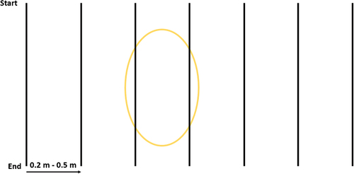
Prior to beginning the GPR survey, a decision must be made as to which orientation to run the GPR lines. GPR is most likely to locate a grave when the orientation of the lines is perpendicular to the long axis of the burial, as it increases detectability. This is visualized in , with having more GPR lines over the grave detecting the grave-related anomalies compared to . In the former, there is an increased chance of locating the grave as well as providing more precise dimensions. Although it is unlikely that the orientation of a clandestine grave will be known prior to the survey, the surface-level changes, such as mounds, depressions, or abnormal plant growth, can help the geophysicist in deciding which way to orient the grid.
Figure 3. Basic multi-line GPR survey set up with perpendicularly oriented grave. The yellow oval depicts the clandestine grave, with the black lines depicting the GPR survey lines. This way, multiple GPR lines can detect the grave-related anomalies, increasing the chances of locating the grave, as well as providing more precise grave dimensions.
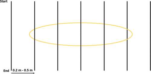
Figure 4. Basic multi-line GPR set up with vertically oriented grave. The yellow oval depicts the grave, with the black lines depicting the GPR lines. This way, there are fewer GPR lines that can detect the grave-related anomalies, potentially affecting the ability to locate the grave and provide more precise grave dimensions. In this scenario, only two GPR lines are covering the grave, meaning only two GPR lines may show a grave-related anomaly. This can be problematic because finding the precise location of grave may be more difficult.
Once the survey grid is laid out, the equipment can be assembled, and the survey parameters can be set. Important parameters include the antenna frequency, estimated depth penetration, time, number of stacks, number of samples per trace, and line/trace increment. highlights the optimal survey parameters for most forensic investigations. Once these are set, the GPR unit can be walked over each line, with the acquisition direction alternated between lines to improve efficiency.
Table 2. Best practice GPR settings for forensic investigations.
The GPR data are shown in real-time on the screen, but this should primarily be used to ensure that the unit is operating correctly. Interpretation of grave locations should be based on processed data, which allows subtle features to be accentuated and the geometry of the anomalies to be determined. Although data processing is not the main purpose of this article, an optimal processing method includes, 1) moving the start time via a static correction, 2) subtracting mean from traces via a ‘de-wow’, 3) applying an energy decay gain, 4) applying a bandpass Butterworth filter, and 5) applying a 2D running average filter.
ERT
The equipment necessary for a successful ERT survey includes an ERT unit (consisting of the ERT machine, metal stakes, and one to two multi-core cables), a car battery, and a tablet/laptop (pictured in ). Additionally, an open reel fibreglass measuring tape, pegs, a mallet, one to two 20 L water containers, and pool salt are also necessary for set up. The total time for an ERT survey (including set up), running Dipole-Dipole and Wenner arrays, is approximately 2 hours, however, the time of the survey itself can be increased or decreased depending on the survey parameters chosen.
The first step is to set out the measuring tape and peg each end into the ground; this will be the base of the ERT line. The length of the line is based on the number of metal stakes available and the desired distance between each peg. For a forensic investigation, the distance between each stake should be no more than 0.25 m. If using a 64 stake ERT unit, the maximum line length can be 15.75 m. The centre of the ERT line should be emplaced over the area of greatest interest, as this is where the depth penetration is greatest. Next, starting at the zero point on the measuring tape, place each stake into the ground and use a mallet to hammer them in. It is best to have them two thirds of the way into the ground. The cable then needs to be attached (there are clearly numbered attachment sites). The first attachment site of the first cable should be attached at the zero point. Once the cables are attached, each stake should be thoroughly watered with salty water (containers of water with handfuls of pool salt added). Some ERT units require a grounding stake. This should be placed away from the ERT line, and close to the machine itself. This stake should also be watered.
The final step is to attach the cables to the ERT instrument, as well as attaching the machine to the battery and the tablet/laptop. This way the unit can be turned on, the contact resistance (CR) can be checked, and the survey parameters can be set. CR, defined in , will dictate how well the electrical current can flow into the ground. If the soil is highly resistive (which can happen when the soil is dry), the data quality will be compromised. Measuring CR can be initiated by the software and will produce a CR value for each stake. For best results, the values should be as low as possible, and similar in number. With high CR values, more salt water can be poured onto the stakes to try and lower it. CR values can indicate if there is something going on with the subsurface (i.e. if a stake is sitting next to a rock, the CR value will be high, and no amount of salt water can fix that. In that case, the peg should be moved slightly), or if the cables are not properly attached to the pegs.
Table 3. Best practice ERT settings for forensic investigations.
Once the CR is assessed, and approved, the survey parameters can be set. Important survey parameters include the electrode interval, the survey configuration, the on/off time, and the output voltage. See for the optimal survey settings. It is important to note that while the ERT survey is running, the pegs should not be touched or moved, firstly because there is electricity running through them, but also because it will skew the data. Once completed, the data file can be saved. Before an interpretation can be done and the location of the clandestine grave can be passed on to the excavation team, the ERT data should be extracted, transformed and filtered,Footnote1 and then processed (exterminating bad data points) and inverted (using a least squares L1 robust inversion) in the appropriate software (the authors use Res2DInv).
Discussion
The literature highlights that GPR and ERT can both successfully locate clandestine graves in a forensic (not experimental) context (see Barone and MaggioCitation48, Novo et al.Citation49, BillingerCitation50, Pringle et al.Citation51, and Fernández-Álvarez et al.Citation52 for forensic uses of GPR, and MoffatCitation53, and Molina et al.Citation54 for forensic uses of ERT), however, they can most effectively be used once the law enforcement agency have a good idea of where the missing individual may be buried, i.e. after other large-scale search techniques have narrowed down the list of search areas (see Donnelly and HarrisonCitation21ʹs Geoforensic Search Strategy – GSS – for comprehensive guidelines on the methods available for grave searches, and Berezowski et al.Citation13 for a multidisciplinary method that explores the use of geographic profiling and LiDAR prior to a near-surface geophysical survey). Then, as GPR is significantly faster than ERT, the list of narrowed down search areas can be surveyed using a grid technique to further narrow down the grave, with ERT being subsequently used to corroborate. Due to the considerably higher set up and survey time associated with an ERT survey, it is not efficient to be used as a reconnaissance tool. Finally, when both techniques are used at the same site, GPR should be used first because the ERT survey requires added salt water in the soil (for better electrical conductivity), which may ultimately affect the GPR results.
The task of utilizing GPR and ERT in missing persons investigations requires specialist skills, as operators need to take into account the soil/climate conditions, the time available for the survey, the necessary depth penetration, as well as the overall data resolution. Survey parameters can be set to get the highest resolution; however, it would be at the expense of survey time and data file size. For example, with GPR, the number of stacks, the number of samples, and the trace increment can all be set to maximize data resolution, but will result in a lengthy survey time, and large data files that may not be manageable on some computers. Survey parameters can also be set to maximize depth penetration, such as increasing the time, however, this will increase the overall survey time (as the walking pace will need to be considerably slower) and increase the file size.
As for ERT, there is a similar relationship between maximizing data resolution whilst still maintaining acceptable survey times, and equipment welfare. For example, the on and off times can be increased, which can increase the signal-to-noise ratio of the data, however, the length of the survey will also increase. Data resolution and depth penetration are also directly tied to the electrode configurations chosen by the operator. For example, Wenner has a high signal to noise ratio (high current), providing quite robust results, however, the resolution is quite low, and will image horizontal features better than vertical ones. The dipole-dipole interaction works well with Wenner because although it has a low signal-to-noise ratio (less current), it produces high-resolution data. The downside of this array, however, is that the survey time is almost double what Wenner isCitation44. An experimental study using geophysical techniques to detect covert burials conducted by Pringle et al.Citation32 found that the Wenner array was optimal. Similarly, Cavalcanti et al.Citation45 found that both showed good sensitivity to the shallow subsurface, however, the Wenner array provided improved vertical resolution. Alternatively, Doro et al.Citation46 found that the Dipole-Dipole array, despite being susceptible to edge smoothening, it was particularly sensitive to shallow low resistivity anomalies (i.e. a covert grave). Ultimately, if time permits on scene, it is optimal to collect both, as they each have their strengths with regards to the quality/quantity of data.
The authors would like to acknowledge that although GPR and resistivity (fixed probe resistivity and ERT) are the two most commonly used geophysical techniques for the detection of covert burialsCitation19, other geophysical techniques such as electromagnetic induction (EM) and seismic (specifically multichannel analysis of surface waves – MASW) methods can also be used. Firstly, ERT was chosen over fixed probe resistivity (seen in research such asCitation55,Citation56) because although it was more time and labour intensive, it produced a profile of the subsurface (whereas fixed probe resistivity data only produces plan view) that could be directly compared to the profiles generated with the GPR data. Additionally, due to the soil at the research site, the CR checks often resulted in high CR which required constant adjustment (i.e. adding more salt water on each peg). This would not have been feasible with fixed probe resistivity equipment. Next, although EM methods are easy to use and may be particularly useful when weapons or metallic objects are included in the grave, it was ultimately discounted due to a recent study that showed that the instrument suffers from signal drift, resulting in a variable response at a given location over time which may compromise their ability to locate the subtle subsurface changesCitation57. Finally, MASW was also discounted due to lack of equipment availability.
Although the emphasis of this article is on the acquisition of GPR and ERT data, demonstrates both the success of the technical protocol presented above, as well as evidence towards each technique’s inability to differentiate between natural and human-made subsurface disturbances. Firstly, the green boxes in highlight the location of a pig burial (the far left and far right box denote single graves with one pig each at 0.5 m and 1.8 m, respectively, and the middle box denotes a mass grave with three pigs at 1 m deep). In the GPR profile (A), the three graves are observable by dislocations to stratigraphic reflectors (or hyperbola). In the ERT data (B – Dipole-Dipole, C – Wenner), the mass grave is clearly observable by a large low resistivity anomaly, however, the single graves, except for the left-most single grave in the Dipole–Dipole data (B), are not. This demonstrates that GPR and ERT may not always be able to individually observe the graves, highlighting the importance of using the techniques in tandem. Secondly, the yellow circles denote natural disturbances with a grave-like geophysical response which could be interpreted as graves due to their depth and size. In the GPR profile and the Wenner array (, respectively), there is a grave-like anomaly detecting a natural disturbance. Similarly, in the Dipole–Dipole data (), there is a shallow oblong high resistivity anomaly detecting a natural disturbance. Although naked burials generally present as a low resistivity anomaly, cadavers wrapped in tarpaulin (a commonly encountered burial scenarioCitation19) are observed as high resistivity anomaliesCitation55,Citation56. Interestingly, this latter anomaly is not mirrored in the GPR or Wenner array data, further highlighting the importance of using multiple geophysical techniques and multiple electrode arrays.
Figure 5. GPR (a) and ERT (Dipole-Dipole [b] and Wenner [c] arrays) profiles of three pig burials that were surveyed 14-months postburial at a research site in Western Sydney. The green boxes denote the three graves; the left-most box is a single grave with one pig that measures 1 m × 2 m × 0.5 m, the middle box is a mass grave with three pigs that measures 3 m × 2 m × 1 m, and the right-most box is a single grave with one pig that measures 0.75 m × 2 m × 1.8 m. The yellow ovals denote areas that could also be interpreted as graves based on their size and depth. The GPR data were processed in ReflexW (1- moving the start time via a static correction, 2 – subtracting mean from traces via a ‘de-wow’, 3 – applying an energy decay gain, 4 – applying a bandpass Butterworth filter, and 5 – applying a 2D running average filter. The ERT data were transformed in R and processed (exterminating bad data points) and inverted (using a least squares L2 robust inversion) in Res2DInv. The Root Mean Square (RMS) values for the Dipole-Dipole and Wenner arrays are 15.5% and 7.9%, respectively.
![Figure 5. GPR (a) and ERT (Dipole-Dipole [b] and Wenner [c] arrays) profiles of three pig burials that were surveyed 14-months postburial at a research site in Western Sydney. The green boxes denote the three graves; the left-most box is a single grave with one pig that measures 1 m × 2 m × 0.5 m, the middle box is a mass grave with three pigs that measures 3 m × 2 m × 1 m, and the right-most box is a single grave with one pig that measures 0.75 m × 2 m × 1.8 m. The yellow ovals denote areas that could also be interpreted as graves based on their size and depth. The GPR data were processed in ReflexW (1- moving the start time via a static correction, 2 – subtracting mean from traces via a ‘de-wow’, 3 – applying an energy decay gain, 4 – applying a bandpass Butterworth filter, and 5 – applying a 2D running average filter. The ERT data were transformed in R and processed (exterminating bad data points) and inverted (using a least squares L2 robust inversion) in Res2DInv. The Root Mean Square (RMS) values for the Dipole-Dipole and Wenner arrays are 15.5% and 7.9%, respectively.](/cms/asset/27ef7ac6-3053-4b7b-a40b-081a99561ca6/tajf_a_2252531_f0005_oc.jpg)
If the data presented in was the result of a search for a homicide victim’s grave, the location of each of the grave-like anomalies would be passed on to those in charge so that an excavation plan could be put in place. It is important to note that although remote sensing methods (such as geophysics) can be used to facilitate large-scale ground searches, excavation is the only way to confirm if any of the anomalies are actually the graveCitation58.
Due to the extensive training and the high-cost for the GPR and ERT equipment, law enforcement may choose to hire third-party consultants to conduct the geophysical surveysCitation27. Additionally, if law enforcement agencies do operate their own equipment, it may still be desirable to hire an expert to consult with the site history investigation and the survey planning, as well as data processing and interpretation. This highlights the importance of fostering good relationships between academics, professionals, and law enforcementCitation27.
Conclusion
In conclusion, this article presented a technical protocol for using GPR and ERT to successfully locate covert graves. Although this protocol was developed in an Australian environment, important survey parameters such as antennae frequency, line spacing, and trace increment for GPR, and electrode spacing and electrode array for ERT, if replicated, may be successful in other environments. That being said, although the specific survey parameters are paramount to the success of a GPR and ERT survey, the soil and climate conditions will ultimately dictate each technique’s ability to observe covert graves. This highlights the importance of experimental studies, replicated in various soil and climate conditions, to better understand when and where GPR and ERT (and other geophysical techniques) work best.
It is important to mention that GPR and ERT do not both need to be used in suite, however, the authors here would like to highlight the beneficial nature of using GPR first, to narrow down a search area, followed by ERT to corroborate the location of the covert grave within the search area.
Despite GPR and ERT being used successfully in forensic investigations globally, they are still highly underutilized. This could be due to a lack of equipment, training, and budget within law enforcement, a hesitancy to use third-party consultans, as well as a lack of general acceptance within the forensic science community.. Ultimately, both experimental and applied research has proven that GPR and ERT can be used to successfully locate covert graves, with the Beaumont investigation being a prominent Australian example (see MoffatCitation53). These successes should be used as justification for the further use of the presented geophysical techniques for missing persons investigations. As such, GPR and ERT can be considered as an evidence-based, and successful, search technique in their covert grave searching toolkit. This way, the judicial process can be facilitated, and these missing individuals can be returned to their loved ones.
Acknowledgments
The authors would like to acknowledge the funding sources, indicated in the funding section, that made this research possible. Additionally, the authors would like to thank The Australian Facility for Taphonomic Experimental Research (AFTER) for permission and space to conduct our project, as well as Ben King for your insight into missing persons investigations.
Disclosure statement
No potential conflict of interest was reported by the author(s).
Additional information
Funding
Notes
1. The authors used RStudio for the transformation and filtering steps, which are written and maintained by Dr Ian Moffat and can be found on Github (Wenner array: https://github.com/IanMoffat/ZZ_ERT_Conversion/blob/main/ZZtoWenner.R and Dipole-Dipole array: https://github.com/IanMoffat/ZZ_ERT_Conversion/blob/main/ZZtoDipoleDipole.R).
References
- Keatley D, O’Donnell C, Chapman B, Clarke DD. The psycho-criminology of burial sites: developing the winthropping method for locating clandestine burial sites. J Police Criminal Psychol. 2021;37:91–100. doi:10.1007/s11896-11021-09457-11898.
- Keatley D, O’Donnell C. Winthropping as an investigative tool in clandestine grave discovery and psychological profiling. J Police Criminal Psychol. 2023:1–13.
- Ferguson C, Pooley K. Australian no-body homicides: exploring common features of solved cases. J Forensic Leg Med. 2019;66:70–78. doi:10.1016/j.jflm.2019.1006.1007.
- Ferguson C, Pooley K. Comparing solved and unsolved no-body homicides in Australia: an exploratory analysis. Homicide Stud. 2019;23(4):381–403. doi:10.1177/1088767919852381.
- Lenferink LI, de Keijser J, Wessel I, Boelen PA. Cognitive-behavioral correlates of psychological symptoms among relatives of missing persons. Int J Cogn Ther. 2018;11:311–324. doi:10.1007/s41811-018-0024-y.
- Lenferink LI, de Keijser J, Wessel I, de Vries D, Boelen PA. Toward a better understanding of psychological symptoms in people confronted with the disappearance of a loved one: a systematic review. Trauma Violence Abuse. 2019;20(3):287–302. doi:10.1177/1524838017699602.
- Hinkes M. Forensic anthropology in cold cases. In: Walton RH, editor. Forensic anthropology in cold cases. Cold case homicides: practical investigative techniques. Boca Raton (Florida): CRC Press; 2017. p. 381–400.
- Larson DO, Vass AA, Wise M. Advanced scientific methods and procedures in the forensic investigation of clandestine graves. J Contemp Crim Justice. 2011;27(2):149–182. doi:10.1177/1043986211405885.
- Rebmann A, David E, Sorg MH . Cadaver dog handbook: forensic training and tactics for the recovery of human remains. Boca Raton (FL): CRC Press; 2000.
- Kalacska M, Bell LS. Remote sensing as a tool for the detection of clandestine mass graves. Canadian Soc Forensic Sci J. 2006;39(1):1–13. doi:10.1080/00085030.2006.10757132.
- Donnelly L, Harrison M. Geomorphological and geoforensic interpretation of maps, aerial imagery, conditions of diggability and the colour-coded rag prioritization system in searches for criminal burials. Geol Soc London Spec Publ. 2013;384(1):173–194. doi:10.1144/SP384.10.
- Corcoran KA, Mundorff AZ, White DA, Emch WL. A novel application of terrestrial lidar to characterize elevation change at human grave surfaces in support of narrowing down possible unmarked grave locations. Forensic Sci Int. 2018;289:320–328. doi:10.1016/j.forsciint.2018.1005.1038.
- Berezowski V, Moffat I, Shendryk Y, MacGregor D, Ellis J, Mallett X. A multidisciplinary approach to locating clandestine gravesites in cold cases: combining geographic profiling, lidar, and near surface geophysics. Forensic Sci Int. 2022;5:100281. doi:10.101016/j.fsisyn.102022.100281.
- Rocke B, Ruffell A. Detection of single burials using multispectral drone data: three case studies. Forensic Sci. 2022;2(1):72–87. doi:10.3390/forensicsci2010006.
- Pensieri MG, Garau M, Barone PM. Drones as an integral part of remote sensing technologies to help missing people. Drones. 2020;4(2):15.
- Alawadhi A, Eliopoulos C, Bezombes F. The detection of clandestine graves in an arid environment using thermal imaging deployed from an unmanned aerial vehicle. J Forensic Sci. 2023;68:1286–1291. doi:10.1111/1556-4029.15280.
- Parrott E, Panter H, Morrissey J, Bezombes F. A low cost approach to disturbed soil detection using low altitude digital imagery from an unmanned aerial vehicle. Drones. 2019;3(2):50. doi:10.3390/drones3020050.
- Evers R, Masters P. The application of low-altitude near-infrared aerial photography for detecting clandestine burials using a uav and low-cost unmodified digital camera. Forensic Sci Int. 2018;289:408–418. doi:10.1016/j.forsciint.2018.1006.1020.
- Berezowski V, Mallett X, Ellis J, Moffat I. Using ground penetrating radar and resistivity methods to locate unmarked graves: a review. Remote Sens. 2021;13(15):2880. doi:10.3390/rs13152880.
- Barone PM, Matsentidi D, Mollard A, Kulengowska N, Mistry M. Mapping decomposition: a preliminary study of non-destructive detection of simulated body fluids in the shallow subsurface. Forensic Sci. 2022;2(4):620–634. doi:10.3390/forensicsci2040046.
- Donnelly L, Harrison M. Geoforensic search strategy (gss): ground searches related to homicide graves, counter-terrorism and serious and organized crime. In: A Guide to Forensic Geology; 2021. p. 21–85.
- Dupras TL, Schultz JJ, Wheeler SM, Williams LJ. Forensic recovery of human remains: archaeological approaches. Boca Raton (FL): CRC Press; 2012.
- Pringle JK, Jervis J, Cassella JP, Cassidy NJ. Time‐lapse geophysical investigations over a simulated urban clandestine grave. J Forensic Sci. 2008;53(6):1405–1416. doi:10.1111/j.1556-4029.2008.00884.x.
- Pringle JK, Stimpson IG, Wisniewski KD, Heaton V, Davenward B, Mirosch N, Spencer F, Jervis JR. Geophysical monitoring of simulated homicide burials for forensic investigations. Sci Rep. 2020;10(1):1–12. doi:10.1038/s41598-41020-64262-41593.
- Killam EW. The detection of human remains. Springfield (IL): Charles C Thomas Publisher; 2004.
- Skinner M, Alempijevic D, Djuric-Srejic M. Guidelines for international forensic bio-archaeology monitors of mass grave exhumations. Forensic Sci Int. 2003;134(2–3):81–92. doi:10.1016/S0379-0738(03)00124-5.
- Schultz JJ. Using ground-penetrating radar to locate clandestine graves of homicide victims: forming forensic archaeology partnerships with law enforcement. Homicide Stud. 2007;11(1):15–29. doi:10.1177/1088767906296234.
- Schultz JJ, Collins ME, Falsetti AB. Sequential monitoring of burials containing large pig cadavers using ground‐penetrating radar. J Forensic Sci. 2006;51(3):607–616. doi:10.1111/j.1556-4029.2006.00129.x.
- Damiata BN, Steinberg JM, Bolender DJ, Zoëga G. Imaging skeletal remains with ground-penetrating radar: comparative results over two graves from viking age and medieval churchyards on the stóra-seyla farm, northern Iceland. J Archaeol Sci. 2013;40(1):268–278. doi:10.1016/j.jas.2012.06.031.
- Schultz JJ. Sequential monitoring of burials containing small pig cadavers using ground penetrating radar. J Forensic Sci. 2008;53(2):279–287. doi:10.1111/j.1556-4029.2008.00665.x.
- Pringle JK, Jervis JR, Roberts D, Dick HC, Wisniewski KD, Cassidy NJ, Cassella JP. Long‐term geophysical monitoring of simulated clandestine graves using electrical and ground penetrating radar methods: 4–6 years after burial. J Forensic Sci. 2016;61(2):309–321. doi:10.1111/1556-4029.13009.
- Pringle JK, Jervis JR, Hansen JD, Jones GM, Cassidy NJ, Cassella JP. Geophysical monitoring of simulated clandestine graves using electrical and ground‐penetrating radar methods: 0–3 years after burial. J Forensic Sci. 2012;57(6):1467–1486. doi:10.1111/j.1556-4029.2012.02151.x.
- Schultz JJ, Martin MM. Controlled gpr grave research: comparison of reflection profiles between 500 and 250 mhz antennae. Forensic Sci Int. 2011;209(1–3):64–69. doi:10.1016/j.forsciint.2010.12.012.
- Moffat I. Locating graves with geophysics. Best Pract Geoinf Technol Mapping Archaeolandscapes. 2015:45–53.
- Bristow CS, Jol HM. Ground penetrating radar in sediments. Bath (UK): Geological Society of London; 2003.
- Ruffell A, McCabe A, Donnelly C, Sloan B. Location and assessment of an historic (150–160 years old) mass grave using geographic and ground penetrating radar investigation, nw Ireland. J Forensic Sci. 2009;54(2):382–394. doi:10.1111/j.1556-4029.2008.00978.x.
- Pringle J, Ruffell A, Jervis J, Donnelly L, McKinley J, Hansen J, Morgan R, Pirrie D, Harrison M. The use of geoscience methods for terrestrial forensic searches. Earth-Sci Rev. 2012;114(1–2):108–123. doi:10.1016/j.earscirev.2012.05.006.
- Buck S. Searching for graves using geophysical technology: field tests with ground penetrating radar, magnetometry, and electrical resistivity. J Forensic Sci. 2003;48(1):1–7. doi:10.1520/JFS2002165.
- Conyers LB . Ground-penetrating radar for archaeology. 3rd ed. Lanham (MD): Alta Mira Press. Geophysical methods for archaeology; 2013.
- Davenport GC. Remote sensing applications in forensic investigations. Hist Archaeol. 2001;35(1):87–100. doi:10.1007/BF03374530.
- Hammon III WS, McMechan GA, Zeng X. Forensic gpr: finite-difference simulations of responses from buried human remains. J Appl Geophys. 2000;45(3):171–186. doi:10.1016/S0926-9851(00)00027-6.
- Loke M, Chambers J, Rucker D, Kuras O, Wilkinson P. Recent developments in the direct-current geoelectrical imaging method. J Appl Geophys. 2013;95:135–156.
- Schmidt A . Earth resistance for archaeologists. Lanham (MD): AltaMira Press. Geophysical methods for archaeology;2013.
- Dahlin T, Zhou B. A numerical comparison of 2d resistivity imaging with 10 electrode arrays. Geophys Prospect. 2004;52(5):379–398. doi:10.1111/j.1365-2478.2004.00423.x.
- Cavalcanti MM, Rocha MP, Blum MLB, Borges WR. The forensic geophysical controlled research site of the university of Brasilia, Brazil: results from methods gpr and electrical resistivity tomography. Forensic Sci Int. 2018;293(101):e101–101. e121. doi:10.1016/j.forsciint.2018.09.033.
- Doro KO, Emmanuel ED, Adebayo MB, Bank C-G, Wescott DJ, Mickleburgh HL. Time-lapse electrical resistivity tomography imaging of buried human remains in simulated mass and individual graves. Front Environ Sci. 2022;10:501. doi:10.3389/fenvs.2022.882496.
- Pringle JK, Jervis JR. Electrical resistivity survey to search for a recent clandestine burial of a homicide victim, uk. Forensic Sci Int. 2010;202(1–3):e1–e7. doi:10.1016/j.forsciint.2010.1004.1023.
- Barone PM, Di Maggio RM. Forensic geophysics: ground penetrating radar (gpr) techniques and missing persons investigations. Forensic Sci Res. 2019;4(4):337–340. doi:10.1080/20961790.20962019.21675353.
- Novo A, Lorenzo H, Rial FI, Solla M. 3d gpr in forensics: finding a clandestine grave in a mountainous environment. Forensic Sci Int. 2011;204(1–3):134–138. doi:10.1016/j.forsciint.2010.1005.1019.
- Billinger MS. Utilizing ground penetrating radar for the location of a potential human burial under concrete. Canadian Soc Forensic Sci J. 2009;42(3):200–209. doi:10.1080/00085030.00082009.10757607.
- Pringle JK, Ruffell A, Wisniewski KD, Davenward B, Heaton V, Hobson L. Historic child homicide burial search in rural woodland. Forensic Sci Int. 2023:100324.
- Fernández-Álvarez J-P, Rubio-Melendi D, Martínez-Velasco A, Pringle JK, Aguilera H-D. Discovery of a mass grave from the spanish civil war using ground penetrating radar and forensic archaeology. Forensic Sci Int. 2016;267:e10–e17. doi:10.1016/j.forsciint.2016.1005.1040.
- Moffat I. How we’re developing underground mapping technologies - lessons from the Beaumont case. Flinders University.
- Molina CM, Wisniewski KD, Drake J, Baena A, Guatame A, Pringle JK. Testing application of geographical information systems, forensic geomorphology and electrical resistivity tomography to investigate clandestine grave sites in Colombia, South America. J Forensic Sci. 2020;65(1):266–273. doi:10.1111/1556-4029.14168.
- Jervis JR, Pringle JK, Tuckwell GW. Time-lapse resistivity surveys over simulated clandestine graves. Forensic Sci Int. 2009;192(1–3):7–13. doi:10.1016/j.forsciint.2009.1007.1001.
- Jervis JR, Pringle JK, Cassella JP, Tuckwell G. Using soil and groundwater data to understand resistivity surveys over a simulated clandestine grave. In: Criminal and environmental soil forensics. Dordrecht: Springer Netherlands; 2009. p. 271–284.
- Hanssens D, Van De Vijver E, Waegeman W, Everett ME, Moffat I, Sarris A, De Smedt P. Ambient temperature and relative humidity–based drift correction in frequency domain electromagnetics using machine learning. Near Surf Geophys. 2021;19(5):541–556. doi:10.1002/nsg.12160.
- Ruffell A, Rocke B, Powell N. Geoforensic search to crime scene: remote sensing, geophysics, and dogs. J Forensic Sci. 2023;68:1379–1385. doi:10.1111/1556-4029.15293.